
FRC Day 8 Build Blog
Day 8: Flywheel
Prototyping
Topspin Single Wheel Flywheel
Today, we iterated on our flywheel prototype. We decreased compression by around a half inch, and found drastically improved results. Our first test had over 90% accuracy. We attached a second motor to be able to test high throughput shooting well. We made our feeder perpendicular to the shooter, and found some shot inconsistency from balls later in the feeder. We realized that a gravity fed shooter might not work well, and added a powered feeder shaft. Our shot-shot consistency improved greatly for high throughput testing, but still isn't excellent.
Testing:
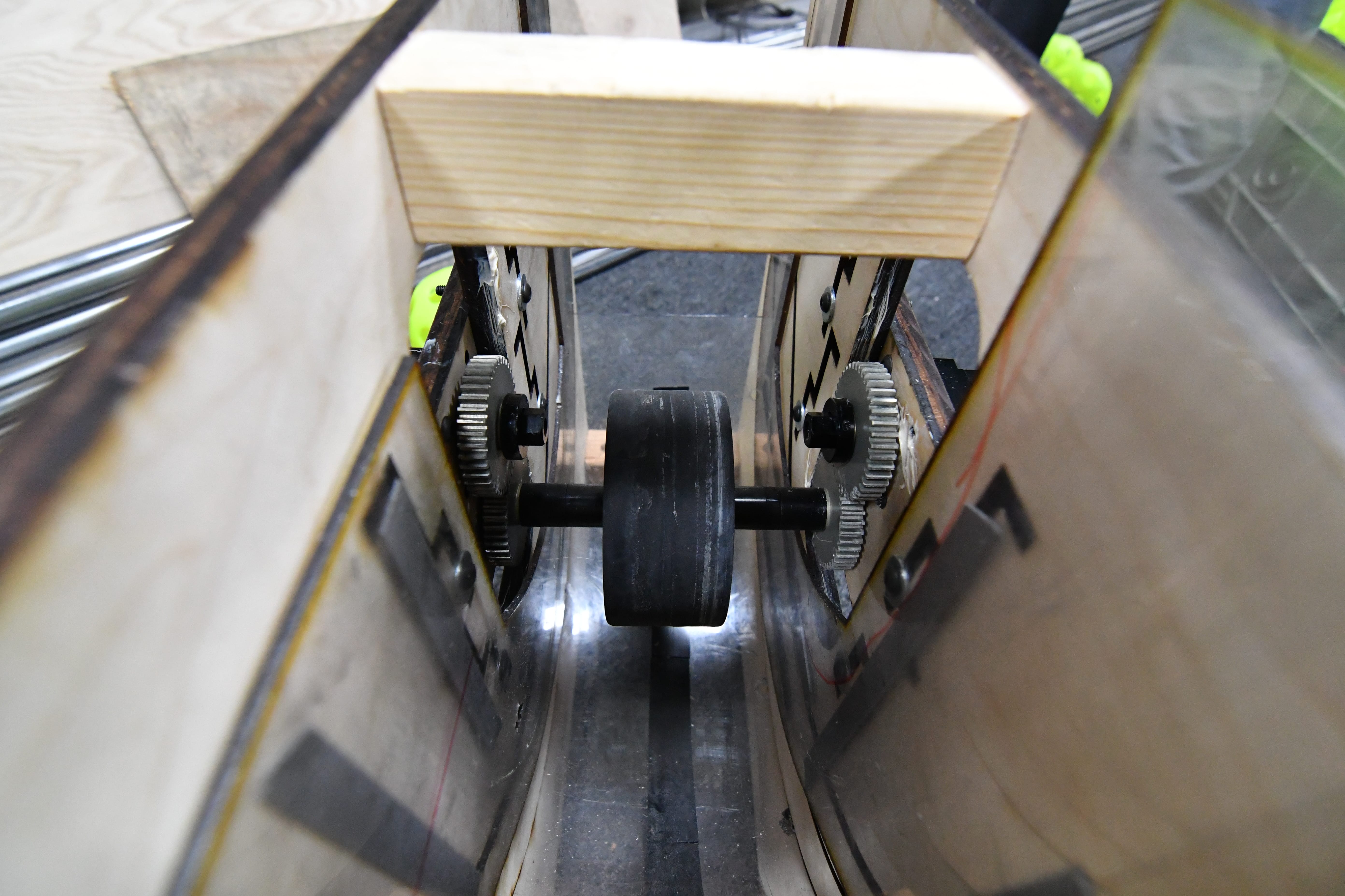
Backspin Single Wheel Flywheel
Today, we worked on a single 2" Fairlane wheel flywheel with 1/4" compression fed by a polybelt feeder, powered by a 1:1 VEX Planetary Gearbox and Motor. The wheel – powered by 2 Planetary Motors – had lots of power, but was very inconsistent. Moving forward, we will want to constrain the shot on the sides as to avoid inaccuracies from side to side (this will most likely be with 1/8" polycarb sheets double-stick taped on). To help the ball shoot more accurately as it exits, we will either shorten the hood so that the ball is in contact with the wheel right before it exits. We may also try to add rollers to improve the shot accuracy. We also had trouble with the polybelt feeder, as the polybelt (which had too much compression on the ball) would skip along the ball as it pulled it up, getting worn down and rendered virtually ineffective in the process. To fix this, we plan to move the feeder out slightly to get the right amount of compression and also have a curved backing so that there are no dead zones in the feeder system. We also plan to make another prototype with a similar design, but less inaccuracies in alignment of the wheel and feeder.
Fuel Intake
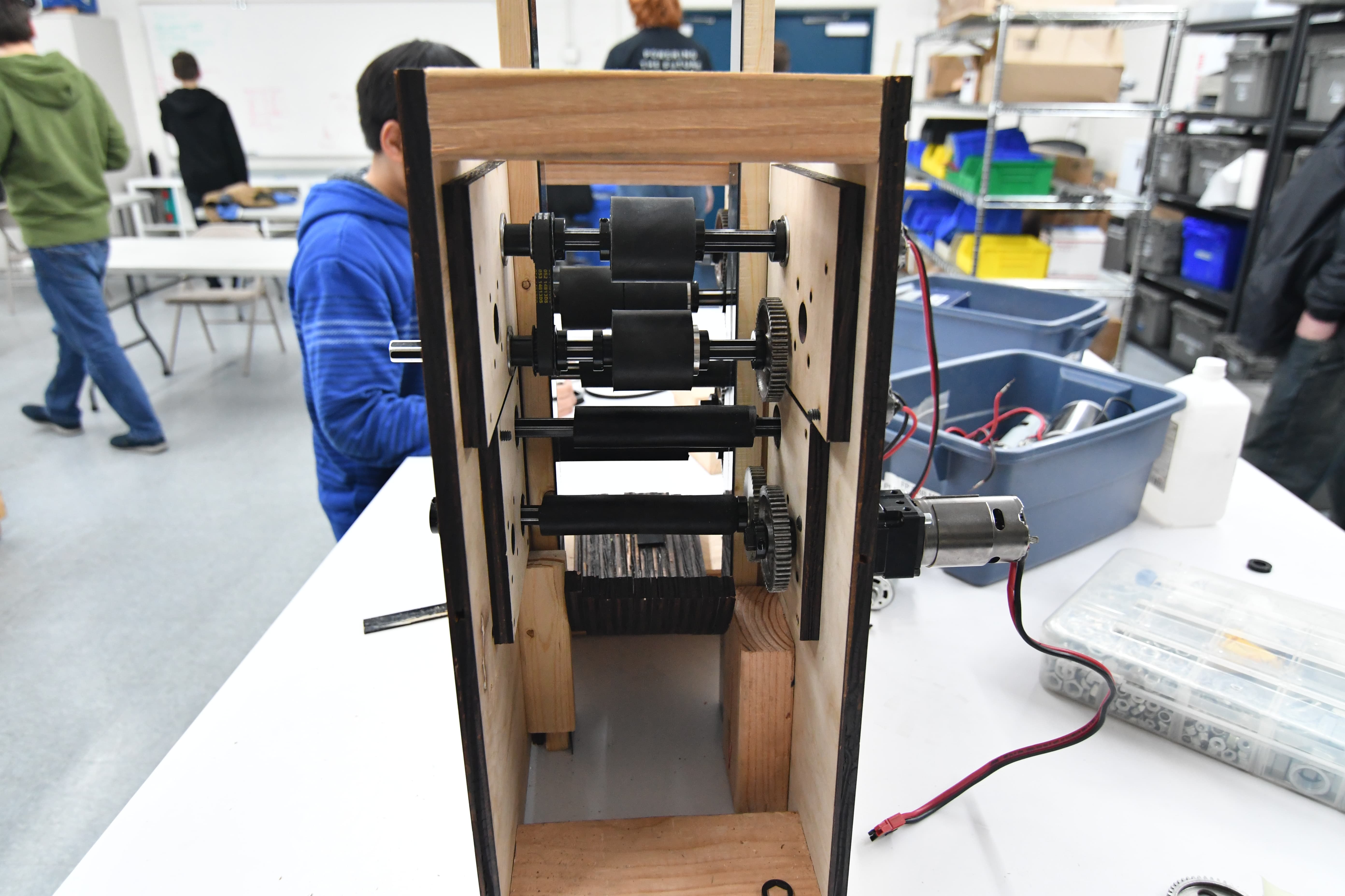
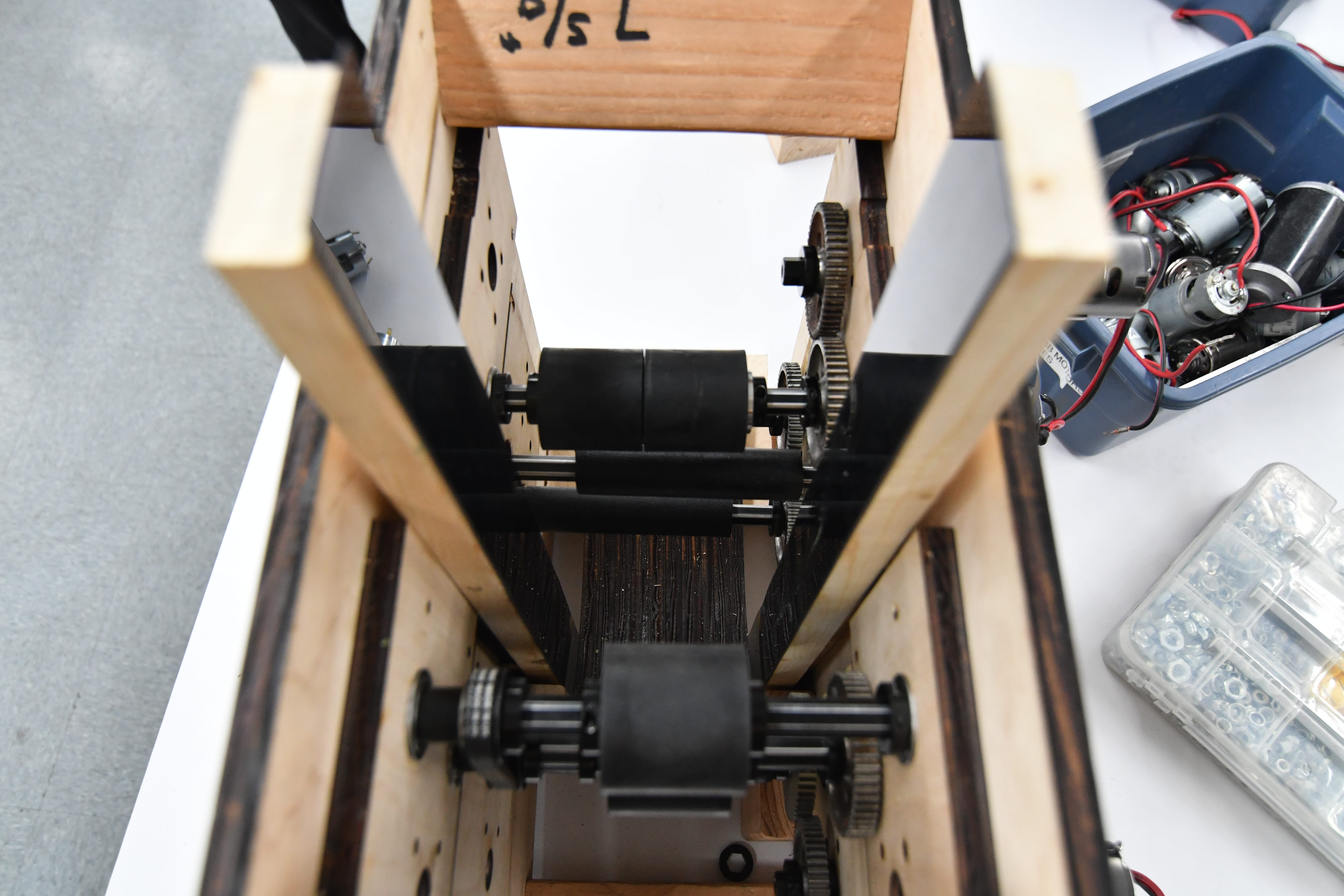
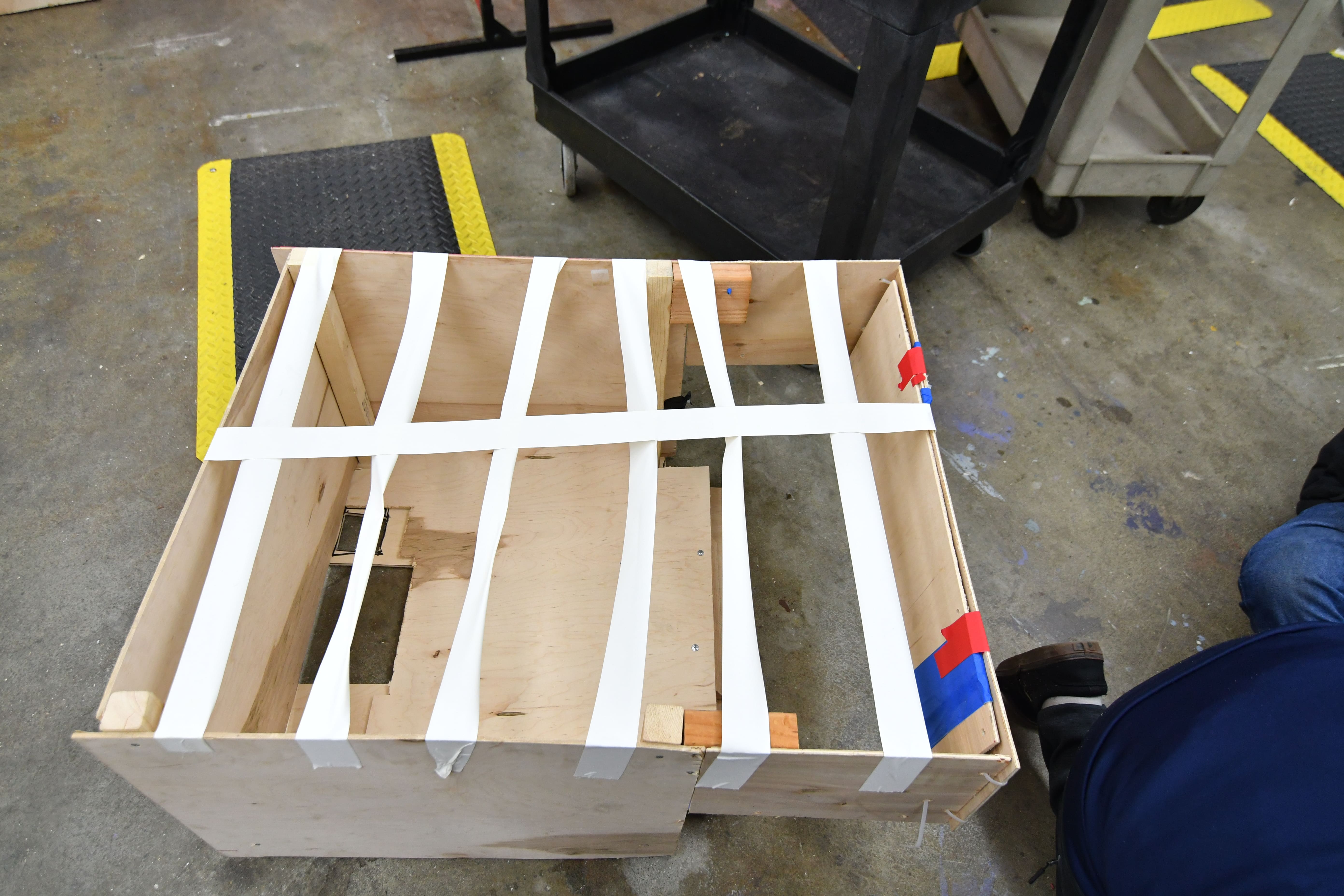
Today we made good progress on the intake. We added two motors (775 Pros) and changed the gear ratio to an overall 3:1. The results were significantly better than the previous test with 1 motor; now, driving at full speed into a dense pack of balls, we were able to pick up almost all the balls and hold them in our hopper. However, this current design uses a small incline right in front of the bumper to help pull the balls up and over, which we would like to get rid of for the final design, because it makes deploying the intake much more complicated. We created a new prototype that does away with the ramp by changing the bottom roller geometry relative to the bumper, and from initial testing, the results looked very promising. More prototyping is needed to see if the new design with no ramp is effective as the previous prototype; however, as the intake nears completion we may prioritize finalizing the shooters.
Testing:
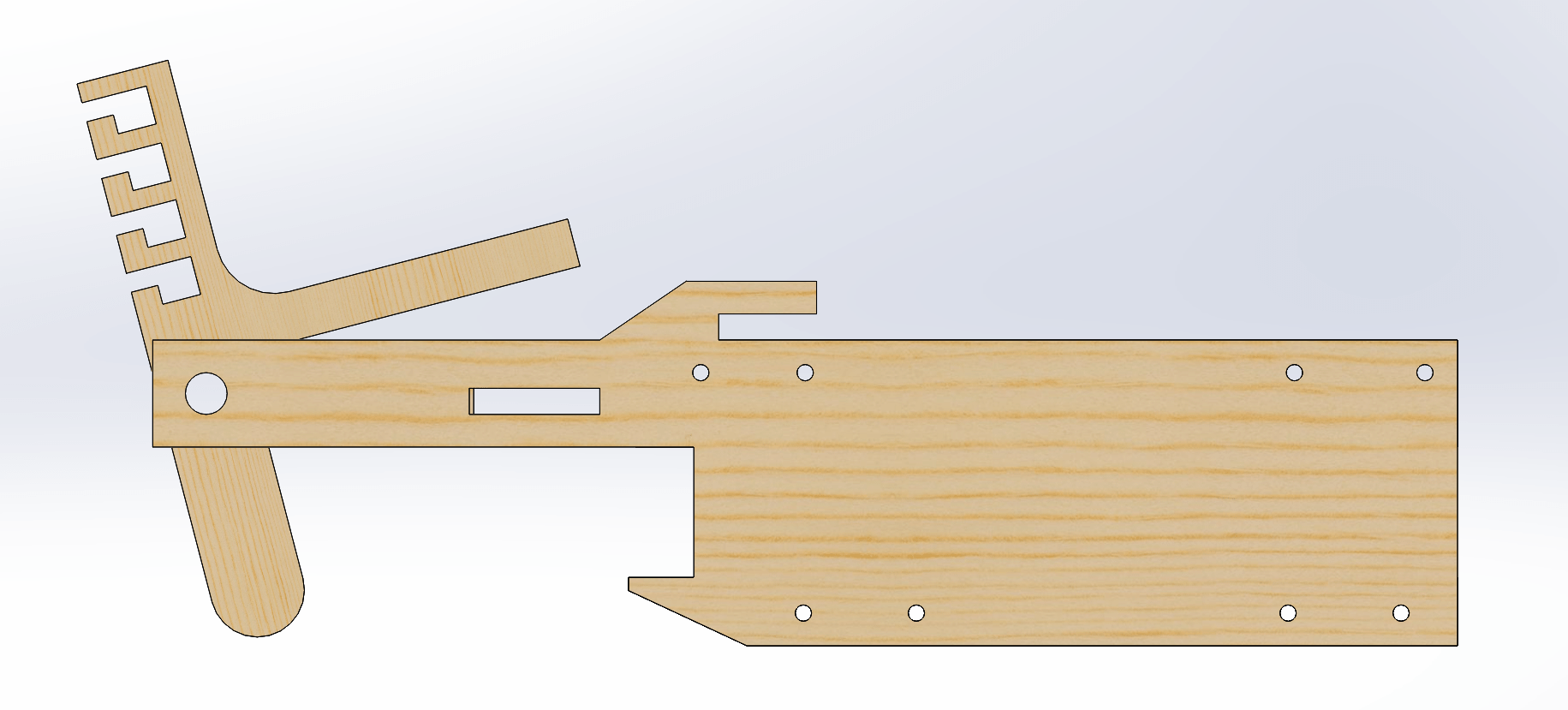
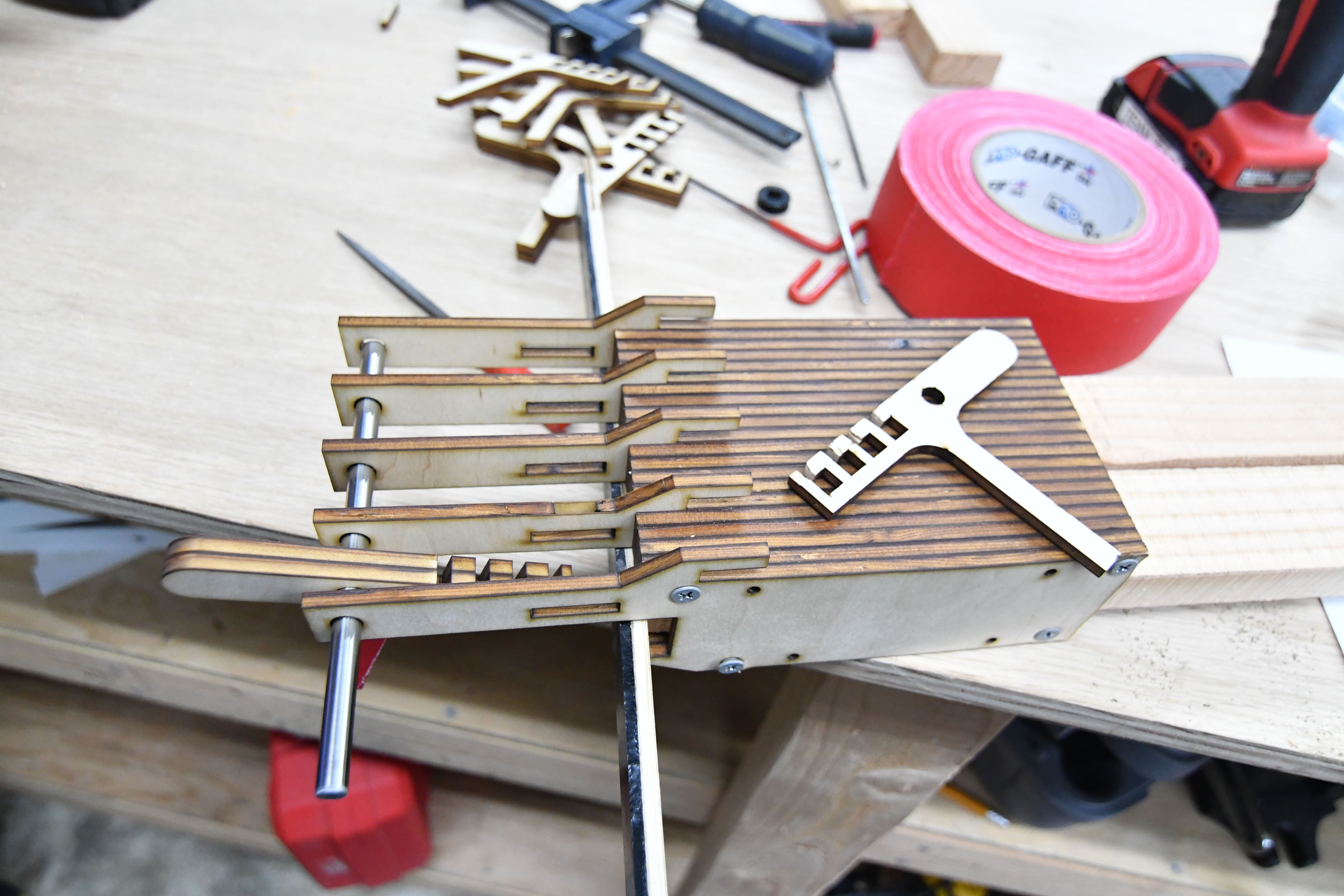
Gear Intake
Today we tried out a completely new design for the gear intake. Instead of placing the pivot point for the hook very close to main body of the grabber, today’s version switched that pivot point to the very front part of the hook. Feel free to compare the picture below to the pictures from the last couple blogs to see the change in design.
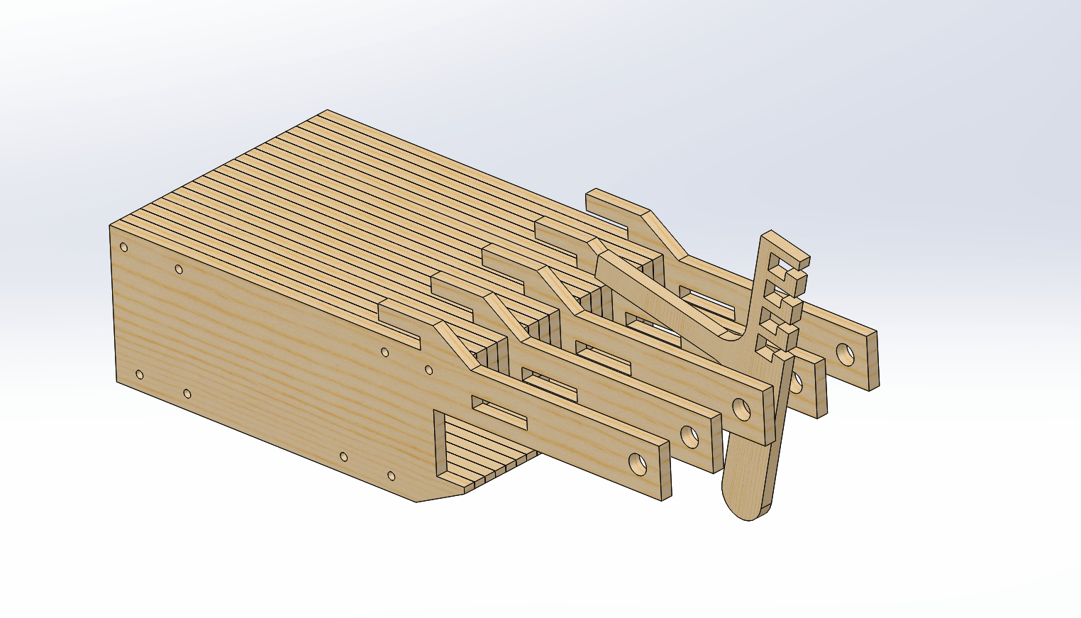
Although we did not finish fully assembling the new design, we believe that this new version will give us a significantly better grip on the gear.. Unfortunately, our initial impression after assembling part of it at build tells us that this new design might actually take up even more space than the previous version, which might outweigh the extra grip. The next step in the development process with involve finishing the construction of this design and evaluate possible areas of improvement. Once we have multiple gear grabber designs working at their full potential, we will compare the different versions and begin designing a metal version for the robot.
Drivebase
We made adjustments to the drivebase CAD by moving down the crossbar to be flush with the baseplate while cutting out slots for chain runs. We also changed the corners on the rear to have a 45 degree slant for better gear intake and made it with two pieces of 1×1 tubing. Moving forward, the last electronics (pcm, vrm) and pneumatics (solenoid/manifold, compressor) have to be finalized in addition to final dimensions.
Programming
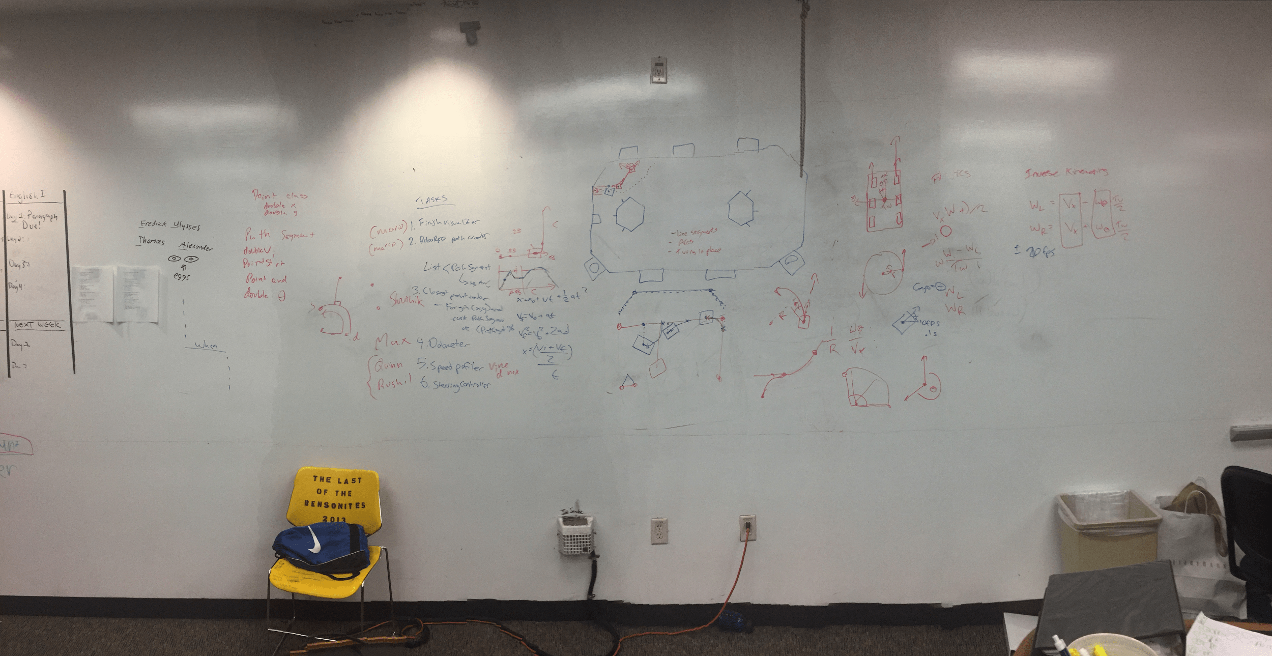
Today, the programming subteam discussed robot motion control with Jared. Moving a robot from point A to B requires waypoints, curvature, and physical constraints of the robot. For instance, a robot cannot instantly accelerate from standstill to full speed, and it cannot instantly decelerate to a standstill without damaging its gearbox components or slipping the wheels. Motion profiling allows the robot to move in a controlled fashion, minimizing acceleration and deceleration.
We also discussed factoring in obstacles like slippage and wrinkles in the carpet. In techno-speak, we would maintain an “odometer” to track our robot’s total movement, then we would calculate the robot’s deviance from the actual path. We would then calculate the closest point on the path, calculate the distance from the robot to the point, then draw a circle using the point as the center and the distance as radius. This path would be used to bring the robot back on track.
We divided the programming subteam up into six projects: finishing the autonomous mode visualizer, creating a RoboRIO path reader that would parse the visualizer output, calculating the closest point, creating an odometer, a speed profiler, and a steering controller. Meeting minutes are in the picture below:
For the PixyCam, we made significant improvements with the SPI interface. The interface works, but with a few bad bytes. We should be able to fix these kinks soon. Also, we’ve made leaps and bounds forward with camera calibration, and distortion is much less of a problem.
