
Build Blog Day 4 (1/12/18)
Drivebase
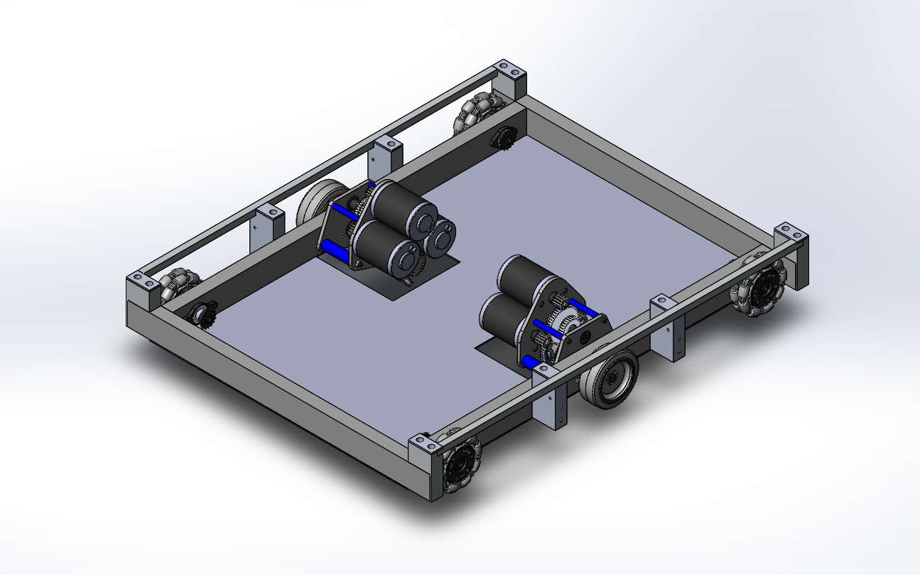
Task: Test different wheel arrangements between colsons and omnis
-
We decided to switch our initial idea of using 6 colsons to 2 colsons and 4 omnis on the drivebase. We also decreased the drivebase width by 0.6 inches to accommodate for the entire width of the colsons. In addition, we added custom wheel shafts into the Drivebase CAD. We also added the gearboxes into the drivebase CAD. This will require us to change the placement of the electronic components.
Gearbox
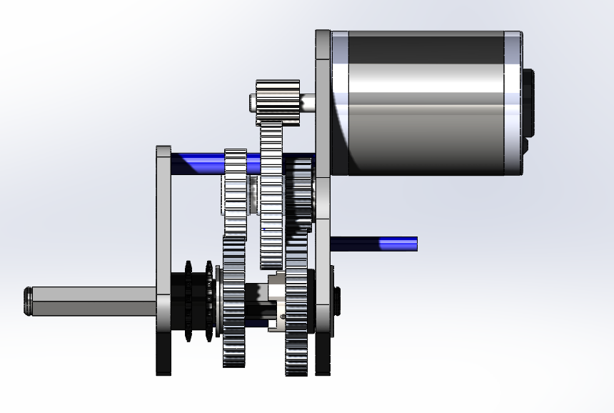
Task: Design drivebase gearbox
-
We started by resolving a few minor issues with packaging Cims around the shifter cylinder. We also realized that we needed more space for components in our gearbox, so we decided to increase the size of the gears between the Cims to fit all necessary components. After fixing these issues, we now have a working gearbox design. At our next build, we plan to finalize the assembly and detail the Gearbox CAD.
Intake
Task: Design intake prototype with two horizontal rollers to pull in and kick up cube
-
We began build by testing the 1st simbotics style intake prototype with 2 sets of wheels. After our testing, our results confirmed that asymmetry is the best way to go forward. Next, we assembled a new intake prototype with a horizontal roller and a kicker roller placed slightly behind the horizontal roller. When testing this prototype, we noticed that the cube would be lifted off the ground and get stuck between the rollers. We plan to keep testing this prototype since the kicker roller showed some promise in getting the cube over the frame rail. Look at Video 1 and Video 2 to see this new intake prototype in action.
-
Lastly, we laser cut version 2 of the simbotics intake, which will be assembled during our next build.

Tunnel
Task: Design tunnel with timing belts to drive the cube across on all four sides
-
The original plan for the tunnel was to have a square tunnel 13”x13” that would have power belts on each side. This way, no matter the orientation of the cube, it would always be in contact with at least 3 sides.
Programming
Task: Test the lidar driver with the roboRIO
-
We worked on the driver, which helps us get data from the RP LIDAR sensor. The sensor gives the distance in mm and the angle in degrees of a detected object.
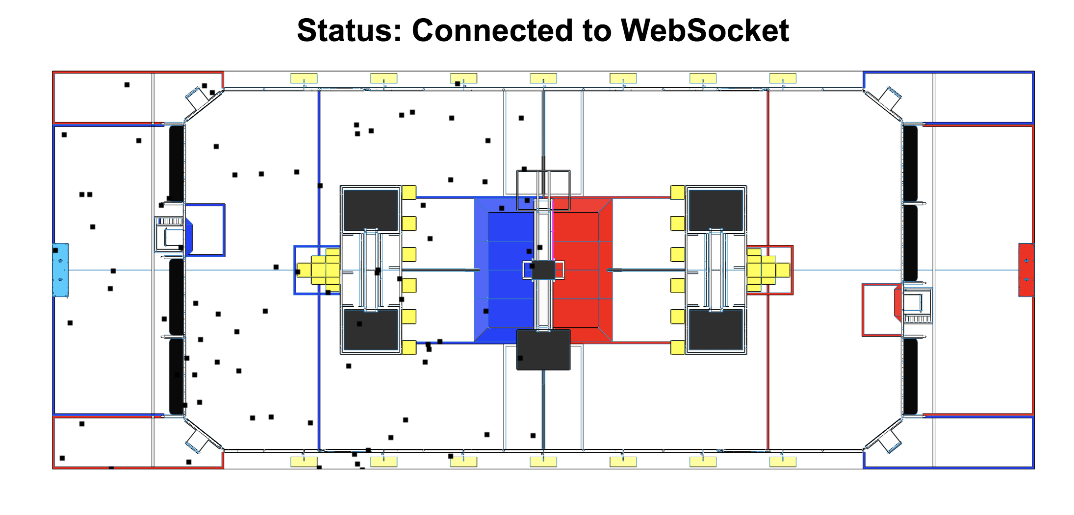
Task: Hook up the visualizer to the robot
-
We also worked on the visualizer by plotting dummy points on a picture of the field. We encountered a few bugs, but fixed them all. Look below for a picture of the visualizer.
Task: Setup and testing
-
Limelight is a camera specifically made for FRC, which makes it easier to use, so we have been experimenting with it. We tuned the vision pipeline specifically for the power cube. In this process, we realized that we had to re-tune the vision pipeline in different lightings, so at each competition we would have to re-tune the pipeline if we were to use the Limelight. The Vision Pipeline is a set of consecutive image processing functions that work to isolate and find specific objects.
