
Build Blog Day 5 (1/13/18)
Drivebase
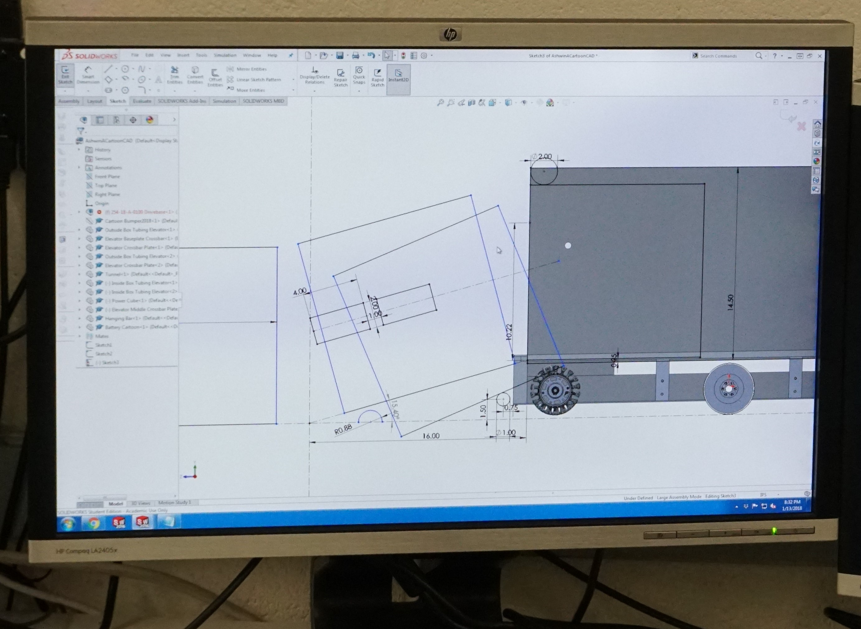
Task: Model drivebase moving up platform ramp with 1/8" center drop and minimal space from outside bumper supports
-
To ensure we have a stable robot when our CG raises with our elevator, we decided to extend our wheelbase as far out as possible. By doing so though, we are more susceptible to high centering on the platform ramp. To ensure we do not do so, we revisited the sketch we used to model the drivebase motion and adjusted the parameters to space the wheels as far out as possible and with a center drop. We also decided to constrain the lowest height of the bearing holes by having the center 16 tooth sprocket with chain OD be tangent to the baseplate. We will account for the chain run by having a cutout in our base plate.
Task: Finalize drive gearbox
-
We finalized the design of the drive gearbox and placed an order for the necessary hardware required (gears, pneumatics, screws, etc.) We hope to begin assembly of the drive gearbox this week.
Task: Sketch electronic placement
-
Task: Sketch electronic placement
We sketched the electronics placement on the baseplate. We plan on having the battery lay flat as in 2017 rather than standing up as in our 2016 robot. This way, we can lower the carriage/tunnel as far down as possible which means the cube does not need to move vertically as much from the ground to the handling mechanism.
Intake
Task: Prototype Intake
-
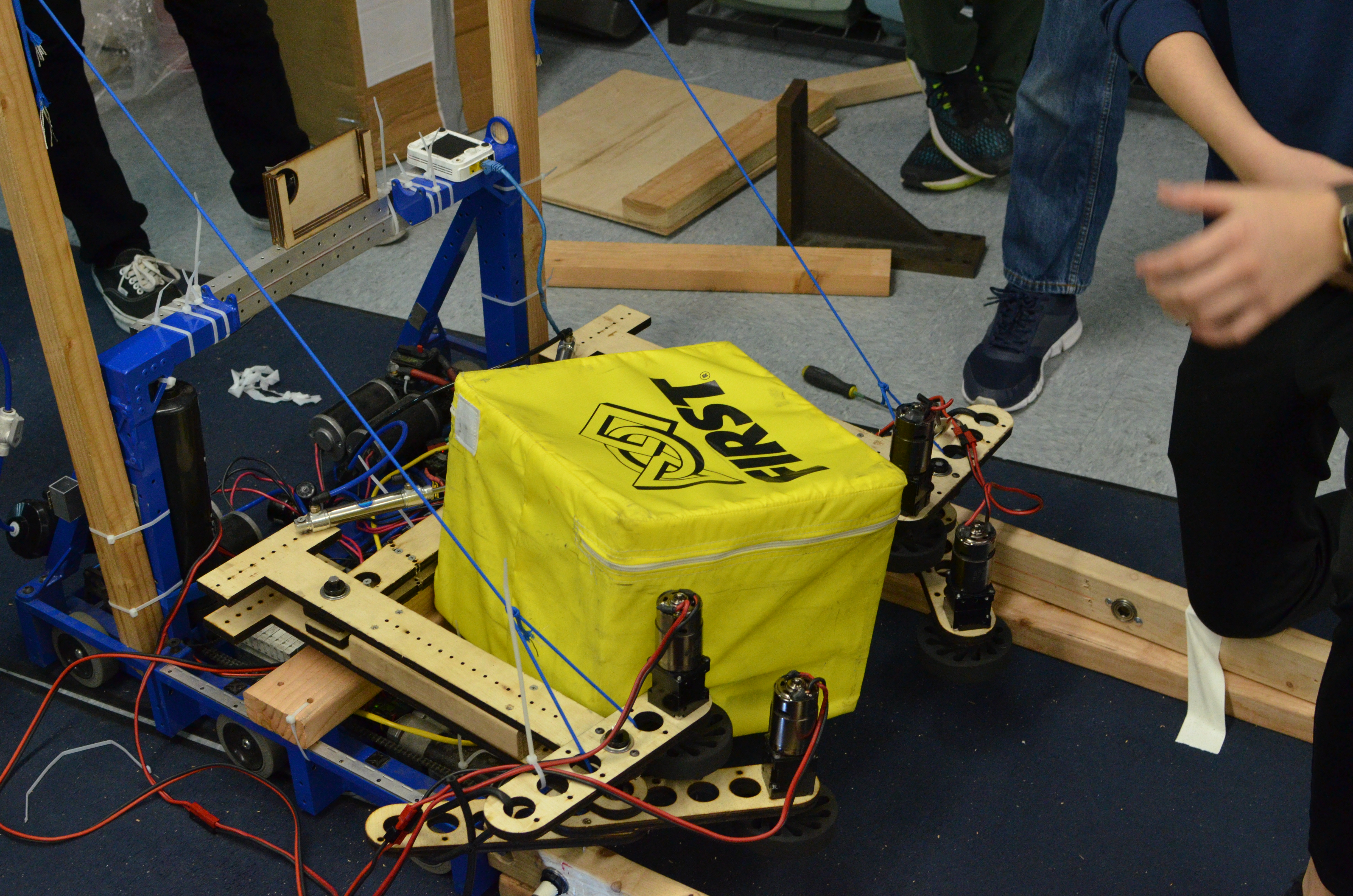
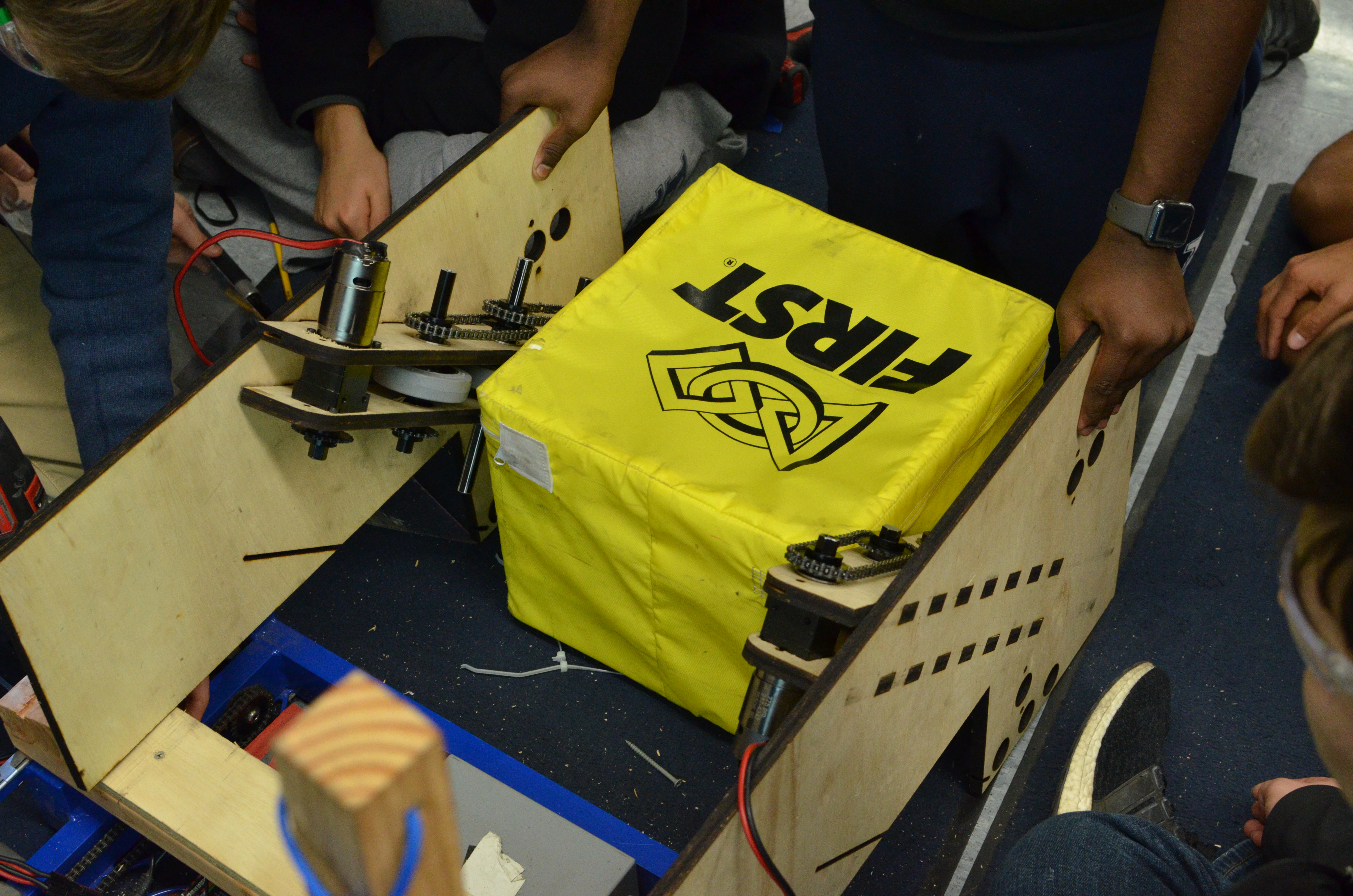
We assembled an intake with adjustable wheel placement and pivotable arms/outer wheels, and mounted it to the 2017 drivebase. We controlled each wheel with its own independent 775pro geared with a 5:1 reduction —- by doing so, we were able to test asymmetry and easily adjust certain speeds of certain wheels. This intake prototype worked well in quickly drawing in the cube and orienting it from a diamond to a square shape. We also saw that by increasing the pressure in the pistons controlling the outer arm pivot, the intake itself became a lot stiffer and was able to better control the cube. We quickly implemented a bottom kicker roller and saw that it worked well because the intake itself was able to provide enough force to push the cube up and above the kicker roller. Moving forward, we will design a prototype that combines this intake with a kicker roller and mount it on a test drivebase.
Task: Prototype ramp intake
-
We design and tested if a kicker roller + a ramp with wheels on either side guiding the cube up would work in transitioning the cube from the ground to the tunnel. While testing, we realized that the wheels on either side did not grip well to the cube (we used colsons) and the transition from the kicker roller to the ramp and wheels was not as straightforward as expected. When the cube goes over the kicker roller, its motion is not very controllable especially when that is the only roller it is contacting. We added a vertical constraint (a piece of 2×4) to stop the cube from being kicked too high, however it deflected the cube from the center of the intake and away from the ramp. Watch this video to see the prototype in action.
Miscellaneous CAD
Task: Cartoon CAD and system integration of robot
-
Today was mostly filled with discussion regarding how best to integrate the various systems of the robot and how to constraint the placement of those systems. In terms of the elevator, we will be moving the outer bars (2×1 box tubing) to sit on top of the frame rails. The outside face of the intermediate stage will come in 0.138" (same clearance used in 2011) from the inside face of the outer bars, and then the carriage tunnel will be another 0.138" in from the inside face of the intermediate stage. This leaves us with around 17" for the width of the tunnel which we think will be enough to handle any orientation of the cube. We also investigated the elevator placement with regards to climbing. To make climbing especially easy on the drivers, we plan on driving straight up onto the ramp and having our bumpers flush against the scale wall and our elevator bar flush against the 2×2 box hanger box tubing. With those constraints, this means our elevator sits 8" from the outside face of our bumper which also means that given we want to spit cubes out on the back side of the tunnel (the side opposite the intake), we need to spit them 8"+. 8"+ is not ideal especially if we want to strategically place a cube, so we need to further investigate how best to optimize elevator placement. We also did line contact calculations on the bearings contacting the intermediate stage from the outside bar, and given that we are hanging 3 robots, then the bearings as well as the aluminum tubing will endure more load than their static load capacity and yield strength, respectively, can handle, To solve this, we tossed around ideas of alleviating a portion of the load from the bearings with a tensile member extending from the top of the intermediate stage to the CG of our robot (the tension of the cable acts opposite to the torque of the robots). Lastly, we decided that to ensure we have a smooth transition from the intake to the tunnel, we will have the intake fixed to the tunnel and not pivot, but will have the entire tunnel + intake system pivot such that it can stow within the frame perimeter, intake horizontally, and place cubes on stacks on the scale.

Programming
Task: RPLIDAR Driver
-
We tested the driver that was already written, but nothing happened. After rewriting some of the code, we were able to send a request to the RPLidar and received some sort of "ok" response, but still, the RPLidar did not start scanning.
Task: RPLIDAR Data Visualizer
-
We worked on some more modifications to the visualizer. We were able to cache all the data sent to the visualizer in an array, so that we could view data with specific timestamps. We also worked on being able to zoom in and pan around the image of the field, so that it is easier to see, but there are still some bugs with this.
Task: Intake Prototype
-
For testing purposes, we remapped the control board so we could toggle each of the four motors on the intake prototype with four separate buttons on the driver station. We also added some buttons to change the speed of the motors on the intake. In addition, we read the drive code, but since last year's programming bot did not have a working compressor for the dog shifters on the drivebase, the robot could not drive.
