
Build Blog Days 8-9 (1/19/2018 – 1/20/2018)
Elevator
Task: Design Elevator Cartoon CAD
-
We worked on finalizing the placement of the elevator. The front face of the elevator will be 9" from the outside of the back bumper. We wanted to move the elevator back because we wanted to ensure as confident a handoff between our intake which will end before the elevator and the exchange, but we also needed to leave space for the roller coaster wheels and the forklift. We decided to place a 2×2 crossbar across with 90 degree angle plugs welded in the ends to dodge the chain and mount to the elevator plugs such that the elevator and the crossbar as a whole can come off as one unit. We finalized the gear reductions for the two speeds of the elevator and packaged the gearbox between the crossbar and the drive gearboxes. The gearbox will mount to the 90 degree plugs.
Top Level Assembly: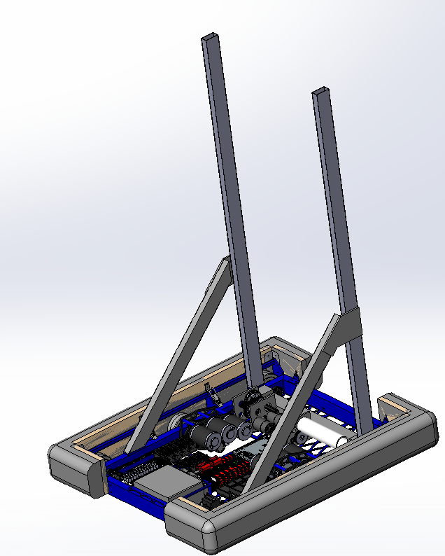
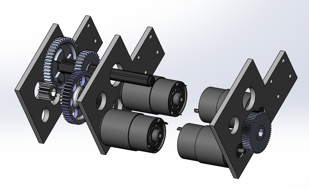
Preliminary Elevator Gearbox:
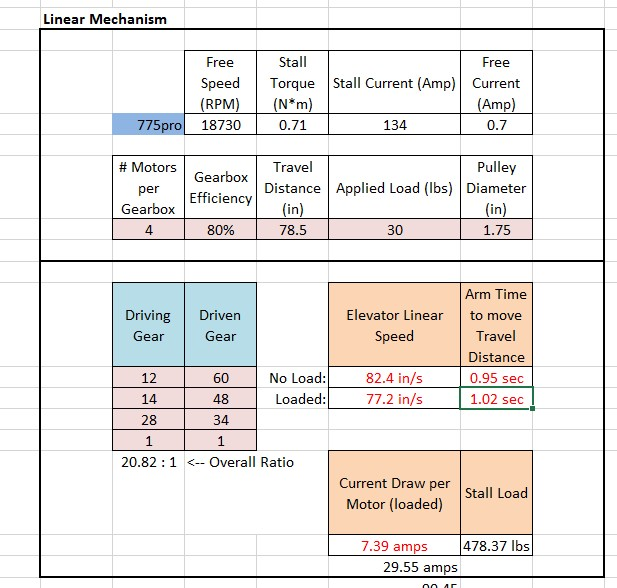
High Gear For The Elevator:
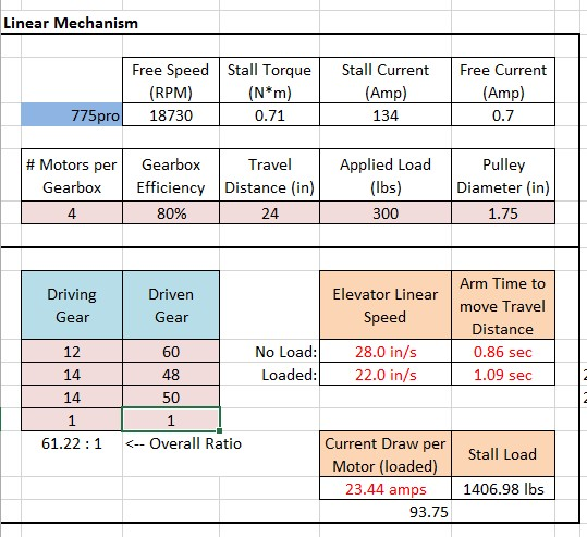
Low Gear For The Elevator:
Drivebase
Task: Finalize Drivebase CAD
-
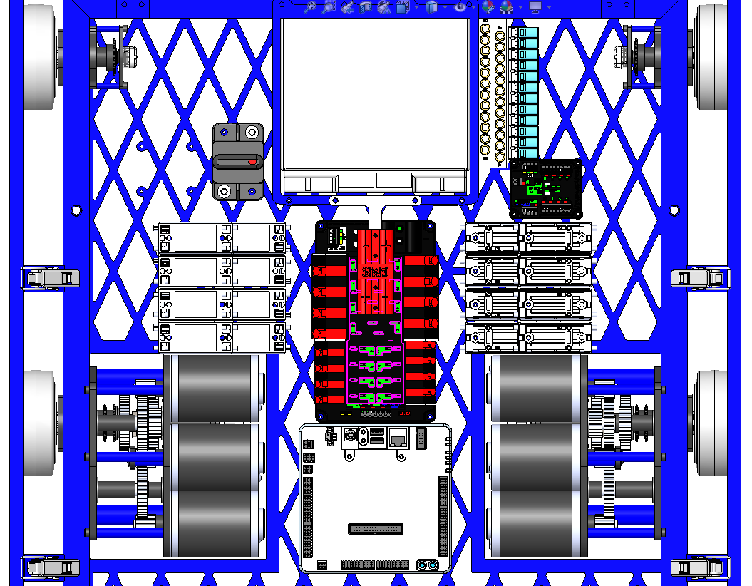
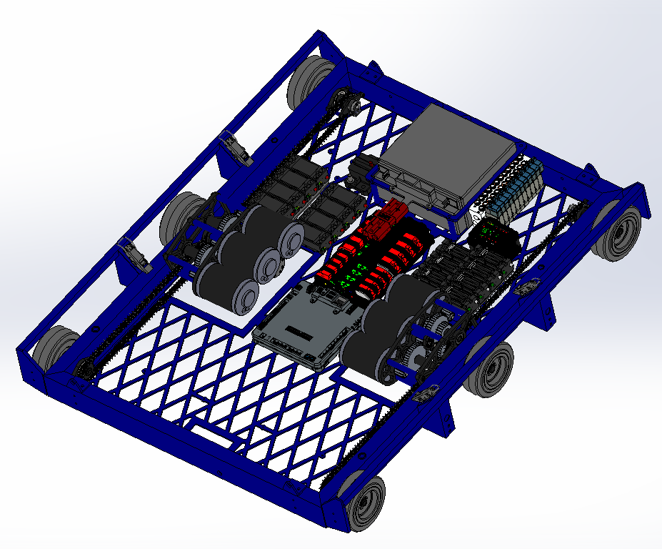
At the last build, we worked on adding mounts for other parts of the robot to the drivebase and also placing electronics. There were a few requirements we kept in mind when placing the electronics including a horizontal battery (instead of vertical placement) to allow for a tunnel, a possible kicker roller in the front, and the gearboxes in the middle of the robot. Keeping these limitations in mind, we placed the battery in the front of the robot (to balance the center of gravity) and the PDP in the middle of the robot with stacked staggered Talons to each side. See the image for placement of everything else.
Forklift
Task: Complete Forklift CAD
-
Yesterday, we worked on the Forklift design for the 2018 FRC Robot. On Friday night, we started by doing some physics calculations to determine how much the forklift would bend once a robot was on it, and determined that a 100lb force at the end of a single 36in rod we plan on using would yield a 6in deflection. This number seemed like a lot, however when we moved the 100lb force to the center of a rod (18in), the deflection was only about 3/4in, which is very reasonable. The next step was to do some sketching in CAD to figure out where the mounting place for the forklift pivot point would be. After trying to make the forklift arms fit in between the bumper cutout (which ultimately didn't leave enough space for a cube to pass through), and trying to make the arms to go over the bumper (which collided with the elevator superstructure when stowed), we finally settled on having the pivot point for the forklift mount on the elevator superstructure itself. With this design, the forklift could stow vertically, and then come down neatly at the end of the match and react against the robot's frame rail when lifting a robot. Now that we have decided to go forward with this design, the forklift design team will need to work closely with the roller-coaster wheel team to make sure that the two subsystems don't collide with one another, as they are both located in very similar parts of the robot.
Rollercoaster Wheels
Task: Complete designing rollercoaster wheels and find methods for mounting/deployment
-
The intention of the rollercoaster wheels is to allow the robot to climb up straight in the sneaky hang, while preventing our partner from falling off the forklift in the partner hang. Our original plan was to have a single plate mounted to the elevator uprights, as well as a actuation deploying the wheels for both the partner hang and the sneaky hang. However, we were unable to package the plate in such a way to stow inside the frame perimeter. Thus, we decided on two separate plates and actuations for each of the rollercoaster wheels. In addition, since mounting the rollercoaster wheels on the elevator uprights would interfere with the forklift deployment, we are pursuing the deployment of the rollercoaster wheels from the bumper frame rail.
Programming
Task: RPLidar Driver with JNI
-
We made some real progress on the RPLidar Driver using JNI. We finished most of the C++ code for the JNI, which again allows us to call functions written in other languages, in Java. To do this, we adapted some of the code from example RPLidar programs for JNI. Once we were done with the C++ code, we built the code into a Shared Object. Our next steps are to finish the Java code, which will load the Shared Object, parse the data returned, and send the data over NetworkTables to the RPLidar Visualizer. Finally, once all of the code is written, we will do some testing and debugging.
Task: RPLidar Visualizer
-
We fixed an error where the RPLidar Visualizer Node.js server was unable to connect to the robot using NetworkTables, which is an implementation of a distributed "dictionary," meaning that named values are created either on the robot, driver station, or potentially an attached coprocessor, and the values are automatically distributed to all the other participants. Also, we updated some formatting on the visualizer to make the timestamp easier to read.
Task: Transforming RPLidar Vectors to XY Coordinates
-
Since the RPLidar scanner only returns an angle (in degrees) and a distance (in mm), we need to be able to transform that to XY coordinates for plotting on the RPLidar Visualizer. To do this, we had to account for the robot's own position and angle, and use some basic trigonometry to transform the vectors into coordinates.
