
Day #20: Funneling Intake and Wiring
Intake
Today, many students worked on the funneling intake. We tested many angles, and elevations, to account for the robot in motion. This funneling intake works through 3 steps. First, the frisbee is sucked in to the intake assembly by a roller that spins over/on top of the frisbee. From there, the frisbee is funnelled by two plastic angled “walls” into a smaller chute. From here, a last conveyor moves the frisbee into the conveyor. Today the students worked on varying the distances the rollers were offset from the ground in addition to the angle/placement of the intake funnels. In addition a team branched off and worked on the CAD for a “real life” model, similar to one that would go on the robot with all variables accounted for.
The final decisions for the intake:
- Funneling walls would be at a 45 degree angle
- The intake will be symmetrical (no staggering of walls to let one frisbee go in ahead of another)
- The funnelling walls and extra lexan pieces would all be made out of one piece of lexan (using bends)
- The back of the intake would rest on the bumpers (students: refer to current CAD in the Sandbox)
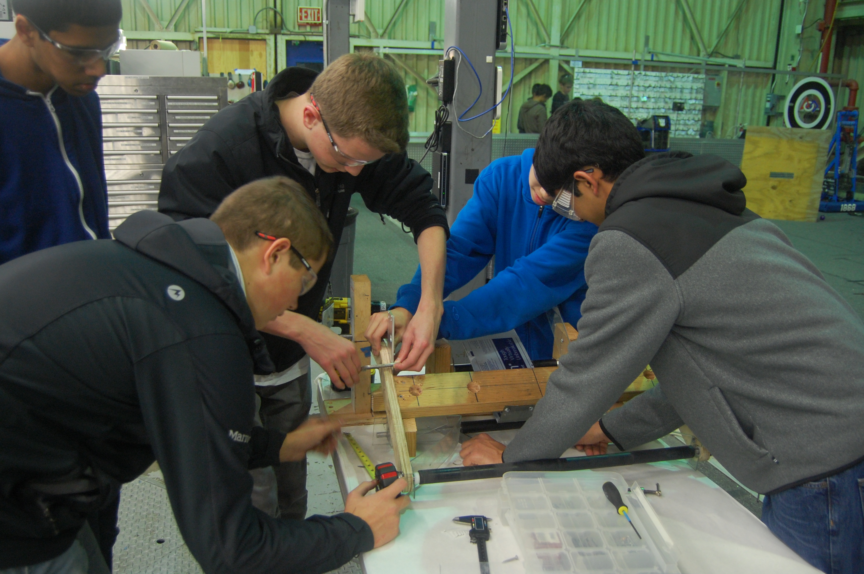
Students test different angles and heights using the wooden prototype
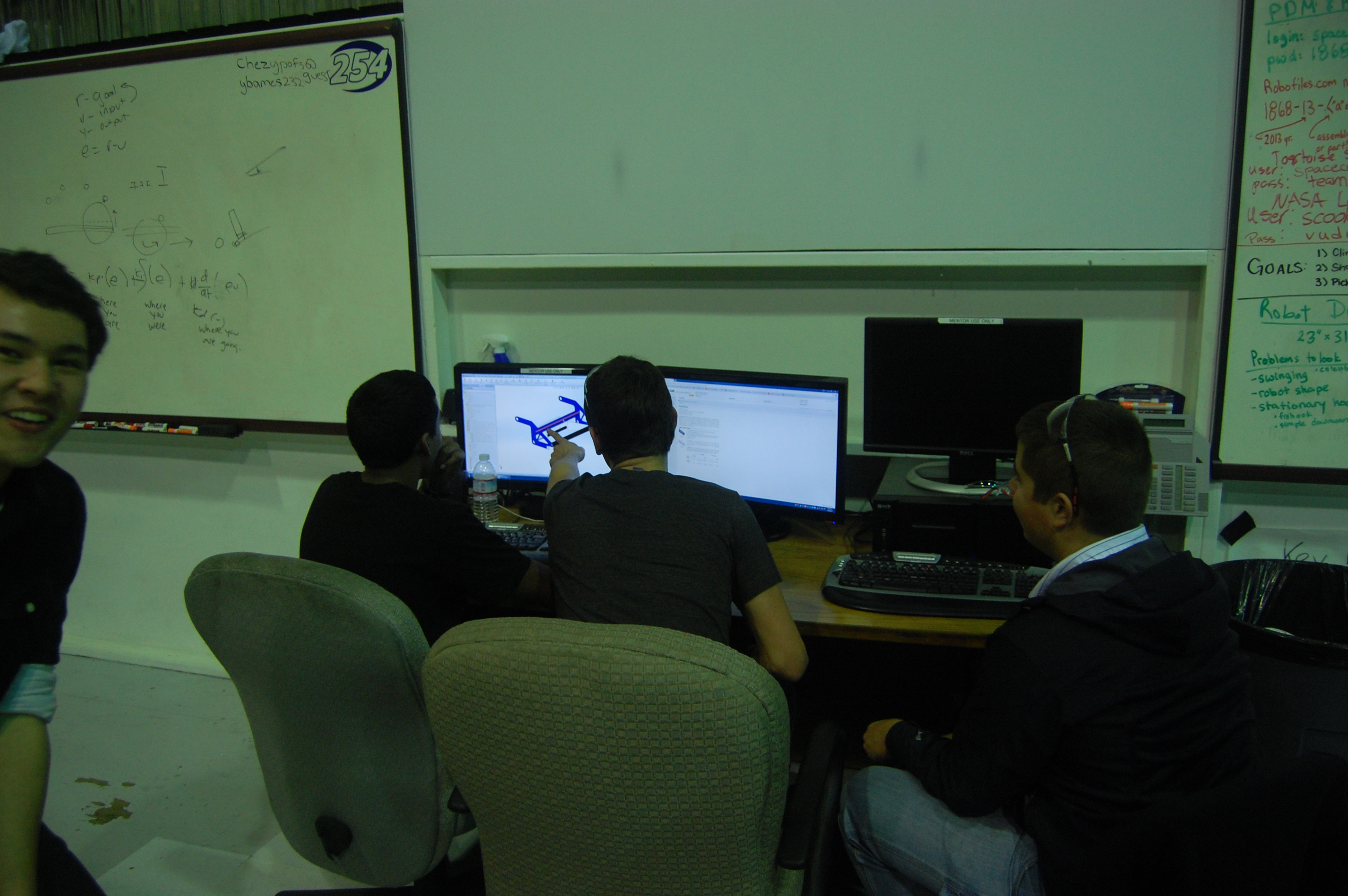
Students model the intake in Solidworks
Wiring
The students and mentors today worked on the electronics for the two chassis we got back from powdercoating. Currently on both the “practice” and “competition” robots, there are Power Distribution Boards, On/Off switches, Talons (speed controllers) and battery boxes. The team began wiring the Talons to the power distribution board.
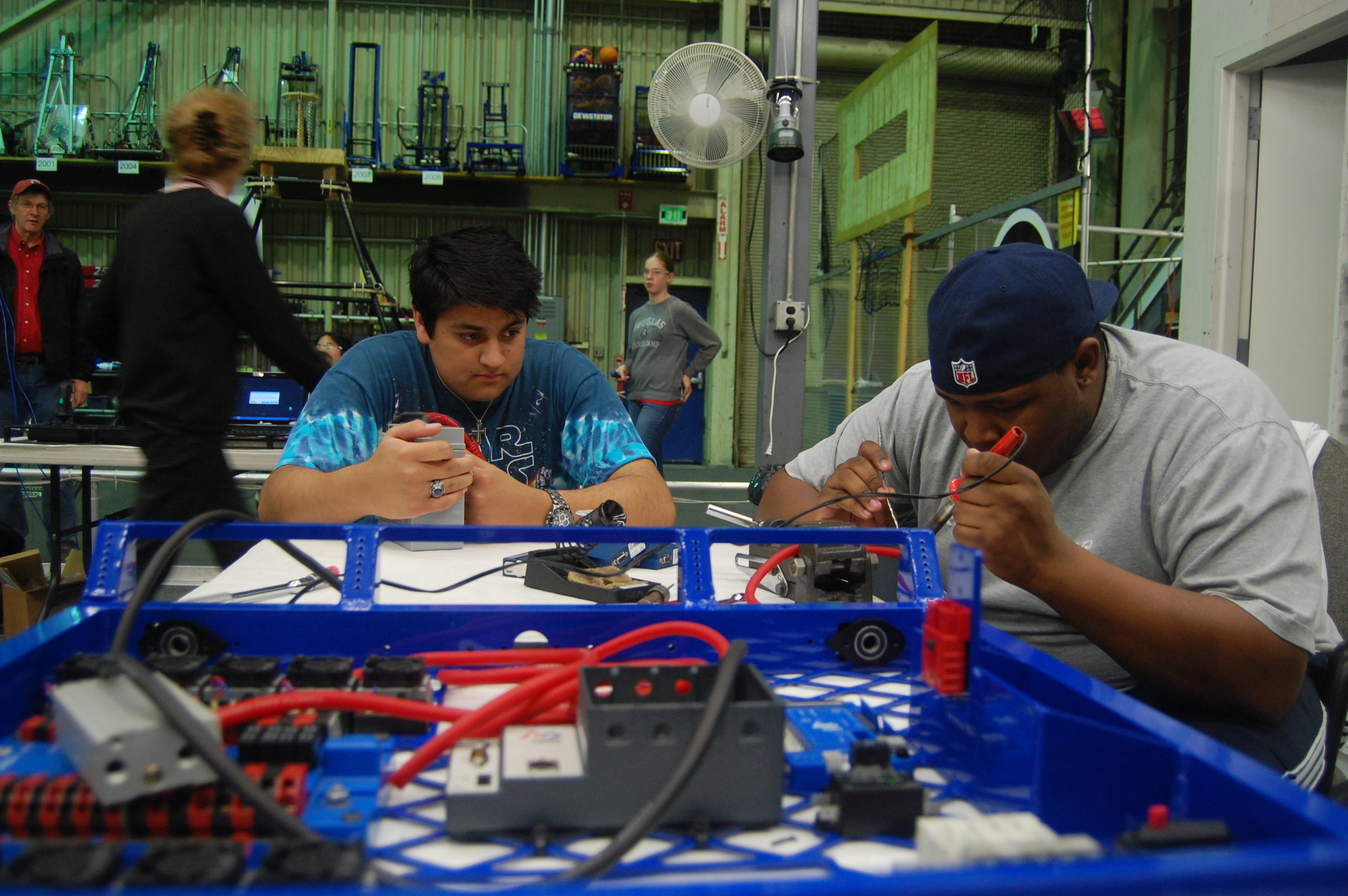
Chassis with electronics
Programming
The programmers began the day by creating a command to shift the drivebase gearbox from high gear to low gear. This was done by creating a Solenoid object and switching it on or off with the press of a button. In addition, the students mapped four buttons on the gamepad (A, B ,X, Y) to the 2012 robot’s shooter. Each of the four buttons, when pressed, sets the shooter wheel at a predetermined speed. This implementation will be helpful for adjusting shooter wheel speeds on the actual robot this year.
Next, the programmers tried to come up with ways to display a graph of values from a Controller (speed, distance, etc) versus time. They brainstormed ideas on how to implement this, such as using the Smart Dashboard or a webpage. Students are looking into Flot, a jQuery library for plotting values on a dynamic graph. This graph will help with PID tuning and other testing.
Action Items
- Continue Wiring Robot Chassis
- Take steps toward a moving drivebase
- Continue on intake CAD/prototyping – Finalize dimensions
Lab closing time for the night was: 11:59 pm
