Day 2: Drivetrain Design & Manufacturing
Today, at the lab, a group of team members met to continue designing the robot drivetrain and continue manufacturing bearing blocks.
Networking & Lab Improvements
We started by networking all of the upstairs computers at the lab together. This will allow us to share printers before the computers. We were able to connect all of these using a switch generously donated by our sponsor, Vivid-Hosting. The networking will be completed tomorrow.
We also procured two power strips which were wired under the floor to provide power to two upstairs tables for laptops. Previously, the lab did not have a good place for laptops to work.
Manufacturing
Manufacturing on the bearing blocks continued today. Progress is being made and the manufacturing will continue into the next few days.
Design
Today, we discussed and decided on several key aspects of the drivetrain.
The first topic of discussion was wheel size. Several team members brought up the idea that with such a flat game field, we could potentially go to wheels even smaller than 4″. Although we quickly ruled out 3″ wheels due to lack of ground clearance (~1/4″ clearance), we were interested by the prospect of 3.5″ wheels which would lower our center of gravity slightly and could decrease drivetrain weight by more than one pound. Furthermore, because less gear reduction is needed with smaller wheels, the weight of the spinning components could be decreased by up to 20%, leading to a potential significant increase in robot acceleration. However, some team members had reservations due to the decreased ground clearance in the move from 4″ to 3.5″ wheels.
To come to a consensus, we created a weighted objective table to weight some of the pros and cons of each design. After much deliberation, the table resulted in almost a tie so we continued to discuss. In the end, it was decided that any problems caused by the decreased ground clearance (1/4″ lower) of the 3.5″ wheel system could be avoided so we decided to move forward with the lighter 3.5″ wheel design. This caused the outer bearing blocks to need edits so that they would not interfere with the newer, smaller wheels.
Benefits of 3.5″ Wheels
|
Benefits of 4″ Wheels
|
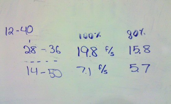
The second topic of discussion was robot speed. After yesterday’s strategy session, the whole team was in agreement that having a fast and maneuverable robot would be key to successful performance in Logomotion. After deciding on small, 3.5″ diameter wheels, we also knew that these smaller wheels would not require as large of a gear reduction as has been present in past robots.
With the ability for a smaller gear reduction, we started with our gear ratios from last year and worked with them to both speed up the robot and minimize the use of large gears to decrease robot mass and increase acceleration. In the end, we found a set of ratios that we liked that will both allow for the fastest 254 robot ever built and for smaller and lighter gears while still maintaining a slower low gear.

Finalized gear ratios for the 2011 robot. Robot speeds are estimated for 3.5" wheels in ft/sec at 100% and 80% efficiency. The first line represents the common reduction. The second and third lines correspond to the secondary reductions for High and Low Gear.
Finally, today was our deadline to finalize the gearbox shafts to be sent out for manufacturing by sponsor Pacific Precision. All four of the shafts were updated and finalized by a team of students. All drawings were checked by team leaders and mentors and were sent to manufacturing.

