
FRC Day 12 & 13 Build Blog
Day 12 and Day 13: Programming and Prototypes
Prototyping
A lot of things got done with prototyping today. We were able to assess the merits of topspin vs backspin, and we determined that the backspin shooter was better for the following reasons after extensive testing:
-
Balls do not jump out of the boiler like the balls with topspin do
-
The angle did not have to be adjusted as much as the topspin one did when we varied the distance
-
Easier packaging
We shot both the topspin and backspin prototypes at the same trajectory and distance to minimize variables, and we tested at three different distances. We did notice that the topspin shooter had a greater allowable RPM range which makes it easier for software control, but the difference was negligible when faced with all of the cons that come with the topspin shooter.
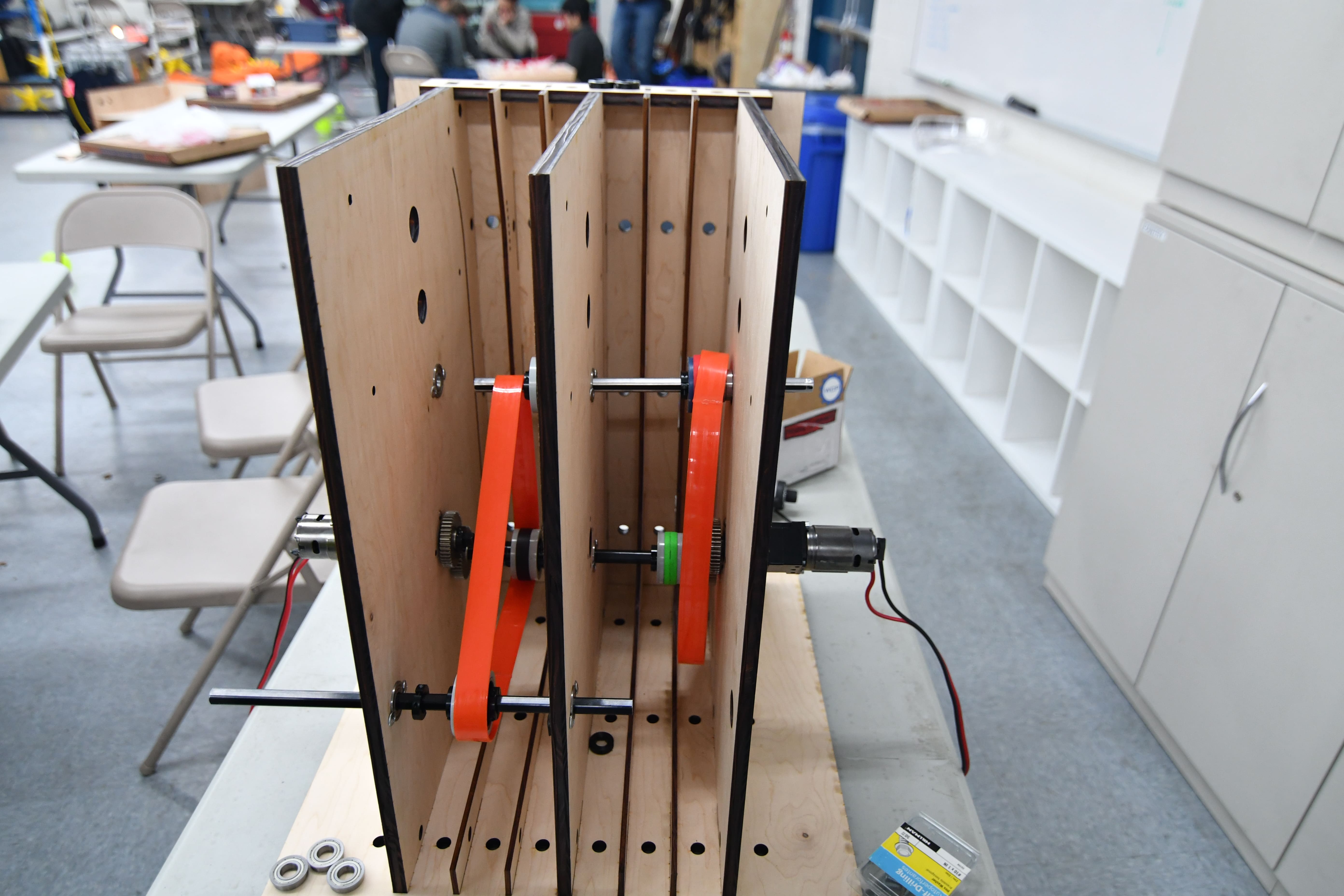
Backspin Flywheel Shooter
After we decided on using a backspin flywheel, we began prototyping a new version that has two channels side by side with a more robust gearbox. This setup shoot allow us to experiment with different variables to determine the best control loop to fire two rapid streams side by side and avoid mid-air collisions. We wanted to remove the inefficiency of the VersaPlanetary gearboxes from our prototypes, so we designed a belted gearbox. We wanted to replicate the 3:1 gearbox which we used for our prototypes, but due to part limitations, could only build an 8: 3 design. We decided that this was close enough to our previous designs and CNCed the parts. We assembled the gearboxes, implemented a polybelt feeder, and added an encoder onto the shooter shaft. After running the gearboxes, we found them to be slightly constrained, but they work and should better replicate our actual shooter. They currently have 4 775 Pros, but we can easily add or remove more motors (max 6). As soon as we get the programming sorted out, we should be able to tune and test this flywheel.
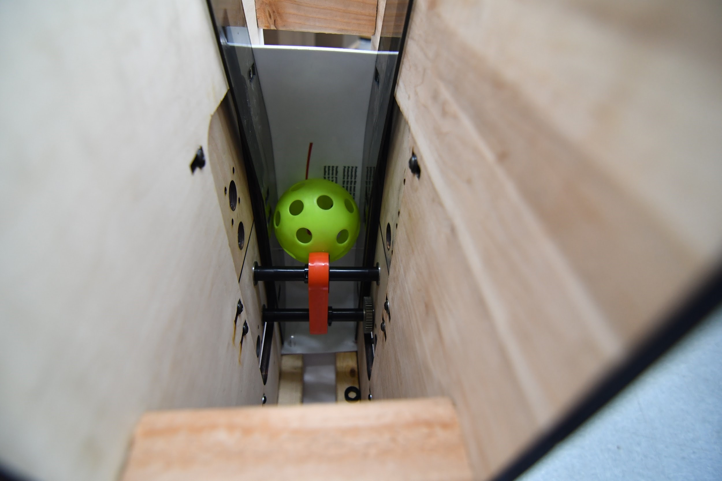
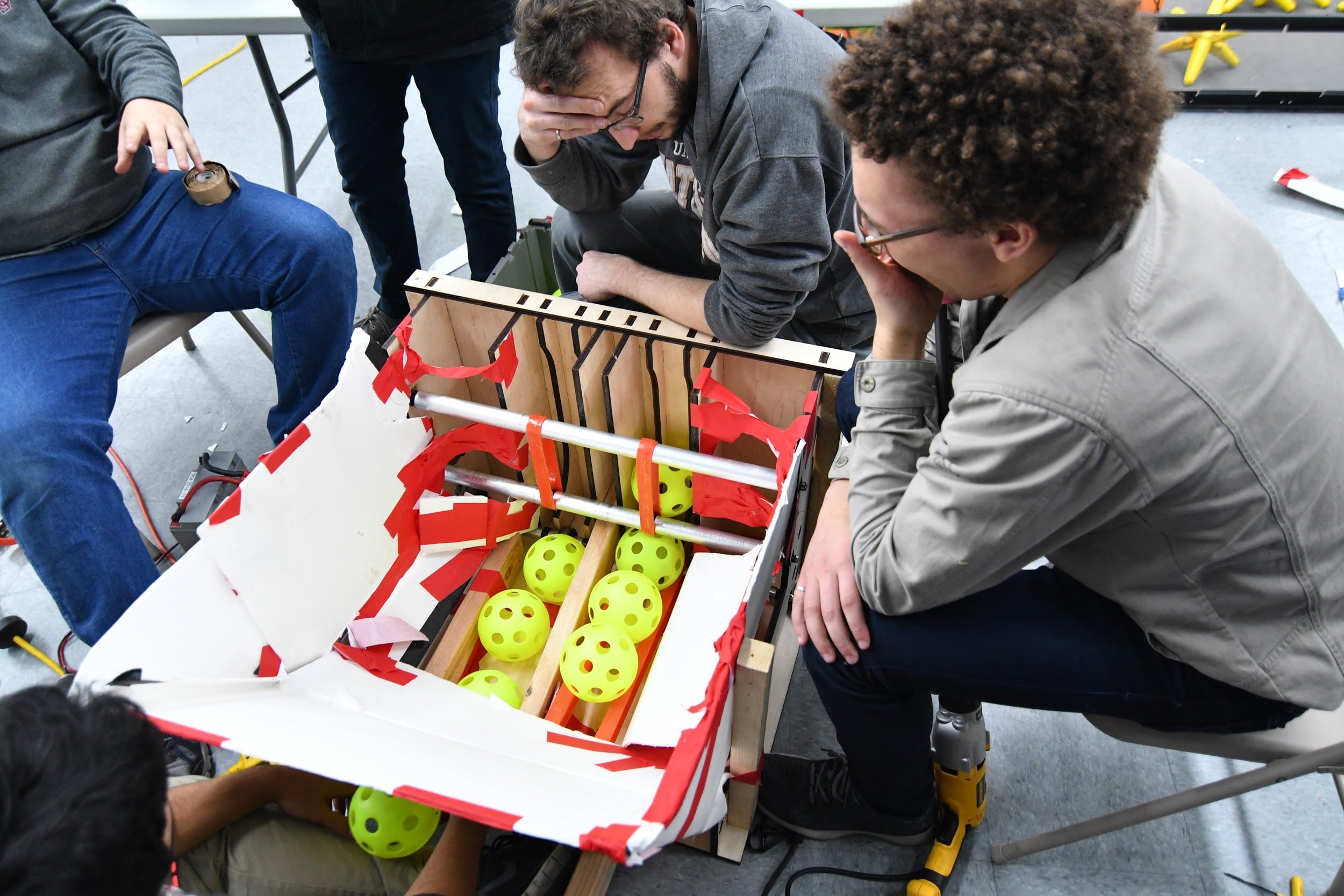
Hopper Conveyor Belt
Today, we also worked on the hopper conveyor assembly. It is currently angled at 5 degrees and has a 3:1 reduction. Using polybelt, it feeds balls into the feeder leading up to the shooter. A funneling feature still has to be incorporated and the assembly itself may be changed depending on results from the hopper prototyping efforts.
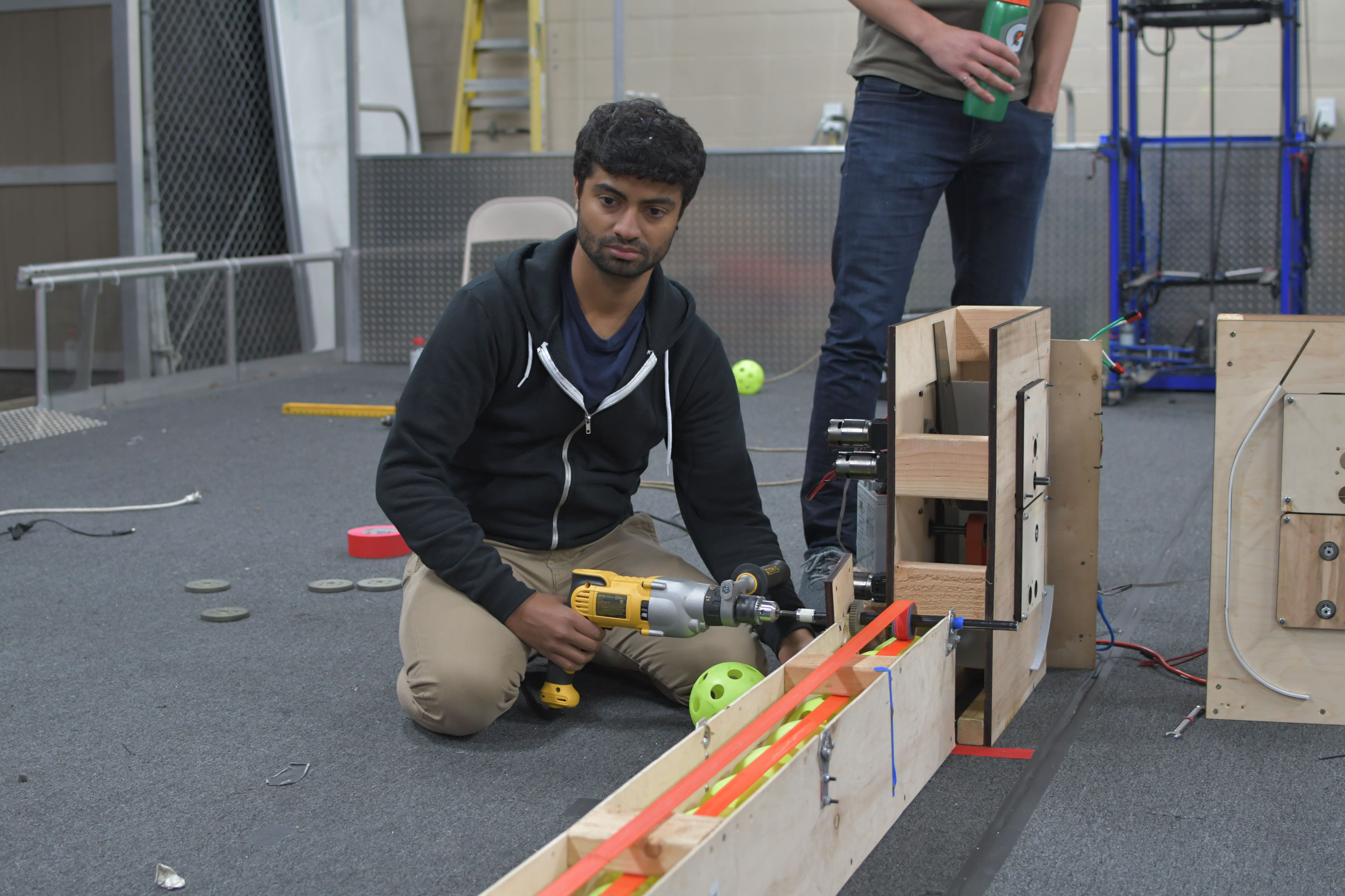
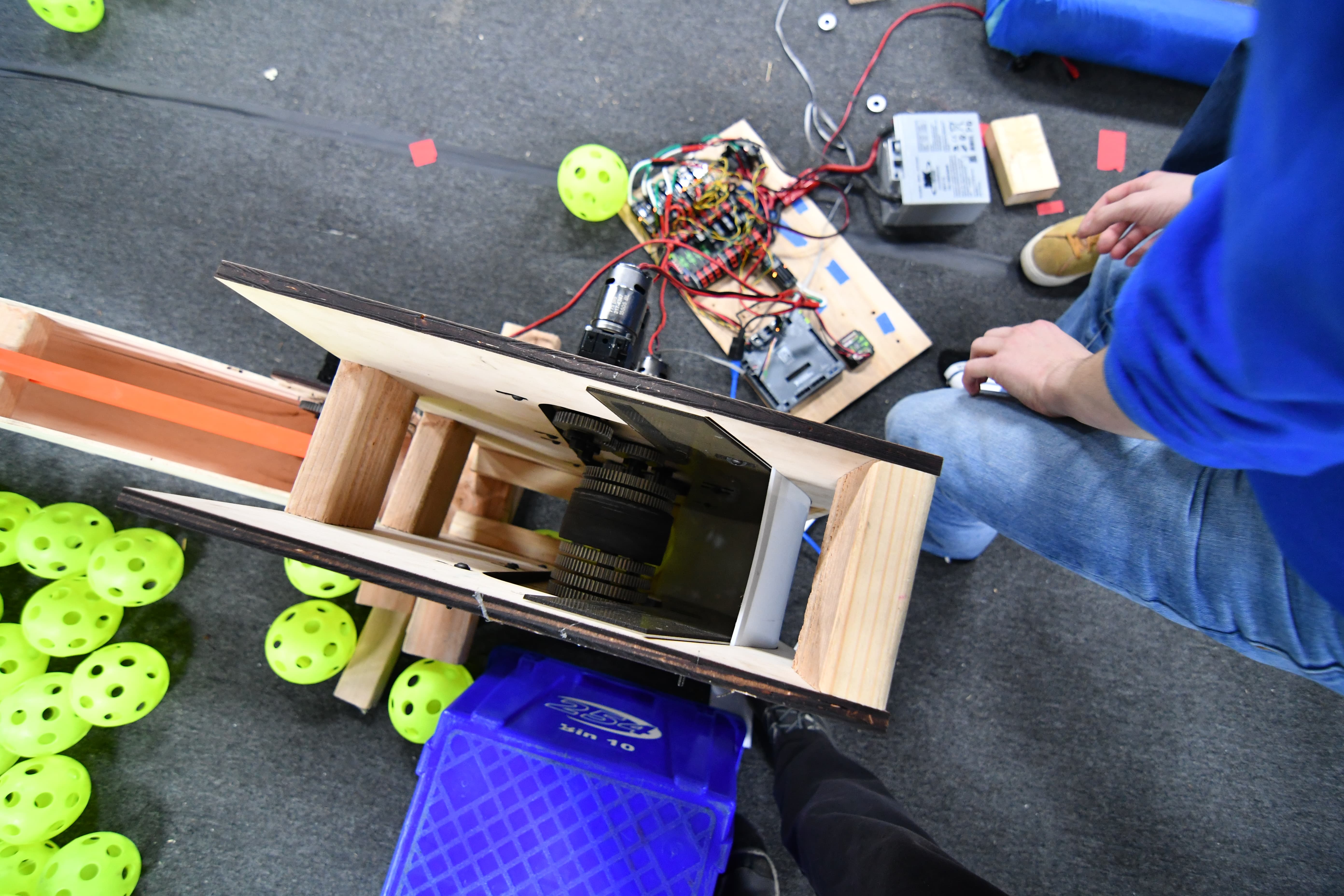
Feeder
Today, we worked on the feeder. Because we were unable to get the previous iteration of the feeder to run smoothly with the output holes, we decided to reduce that number to two and make a few other small modifications to the general design. This new version was then designed and constructed, but we found that the improvement was not as significant as we originally imagined it would be. In fact, we still had problems with the motors burning out and we really struggled to get a lot of balls to run through the system. In order to solve this problem, we tried a couple of things. First, we tried adding zip ties to some parts of the roller, but this simply caused jamming. Second, we tried increasing the spacing between the two output holes as making them significantly more defined. This, unfortunately, did not help that much. Finally, we tried using a drill with some wheels on the end to agitate the balls, somewhat like a KitchenAid mixer. This helped a bit more, but we still reached the conclusion that it was simply a bandaid to a bigger problem.
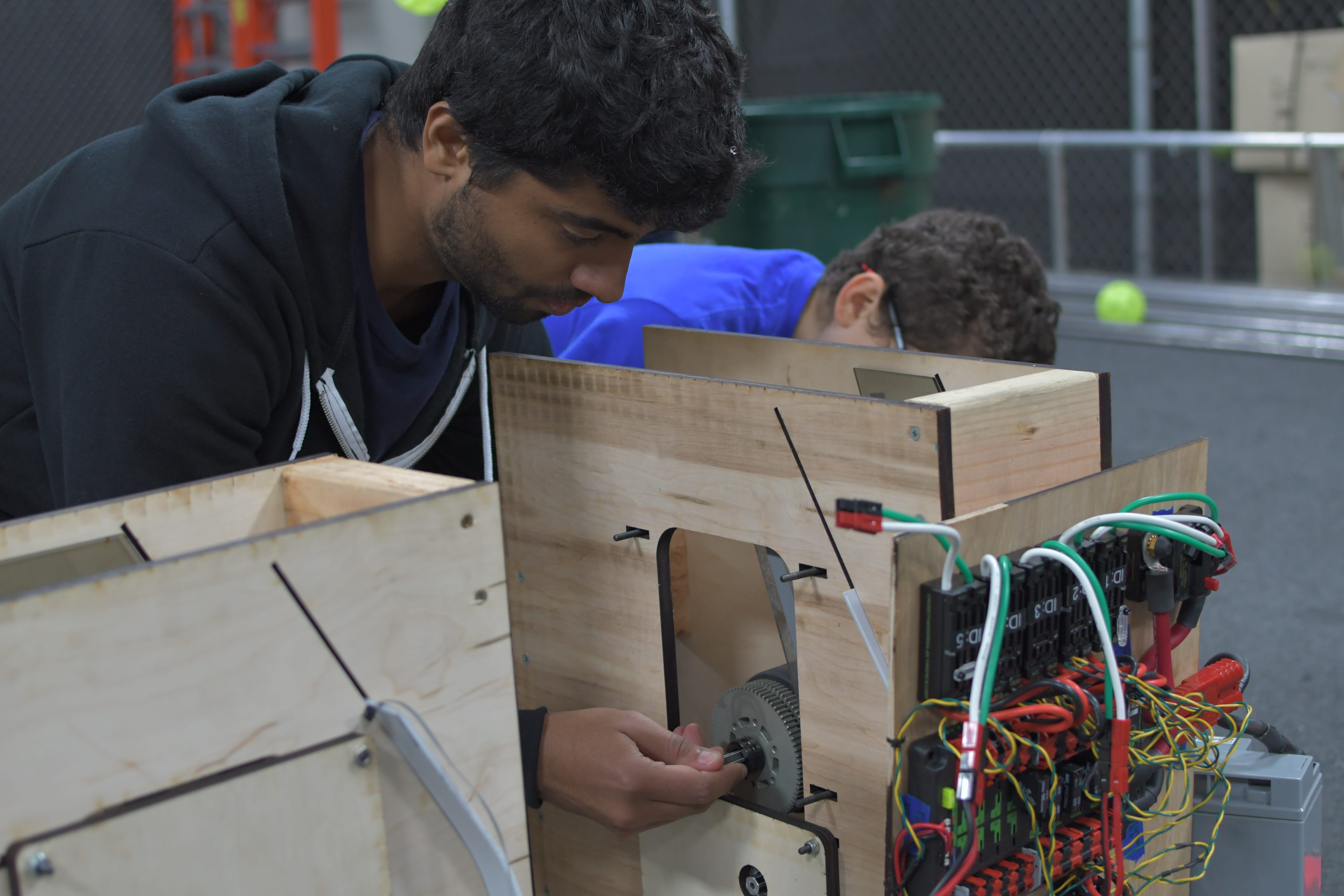
Manufacturing
For these two builds, we manufactured all the parts for the drivebase and began assembly. Because of design changes, we manufactured all the parts for the bumper mounts on the manual mill. We also prepped the belly pan by countersinking the holes for the rivets and deburring it after getting it from the water jet.
Programming
Shooting Control
Today, we began to brainstorm better ways to control the flywheel, and we arrived at the following scheme (which we call the JRAD Controller):
v[t + dt] = kf + kj * dt * (kLoadRatio * setpointSpeed – curSpeed)
Where dt is measured cycle time, kj and kLoadRatio are tuned/calculated, and kf is set to some constant like 8 (Volts)
This equation represents the initial version of the JRAD controller (named after Jared, who made the equation). This version is actually incorrect, and next build we will be adding an additional term to make it an integrating controller as opposed to a proportional + constant term controller. This new equation will be:
v[t + dt] = kf * setpointSpeed + v[t] + kj * dt * (kLoadRatio * setpointSpeed – curSpeed)
Where v[t] is the previous cycle’s output in volts, and where kf is multiplied by the setpoint so that it works at more than one speed
What this controller does it that it anticipates the drop in RPM during a stream of balls, and increases the RPM set point accordingly. This adjustment is the kLoadRatio, which is the key feature of this controller.
To tune the controller, you would start with kLoadRatio at 1, kj at some nonzero small number, and kf also at zero (kf allows the controller to reach the steady state faster, but is never necessary). Here is the initial scenario:
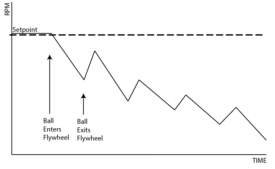
The difference between the dips when balls hit indicate that the controller is not tuned correctly. Each valley should be at the same height, even if it is below the steady state. KJ should be increased in the above scenario. If the valleys increase over time, then KJ should be decreased. Eventually the RPM vs Time chart should look like this:
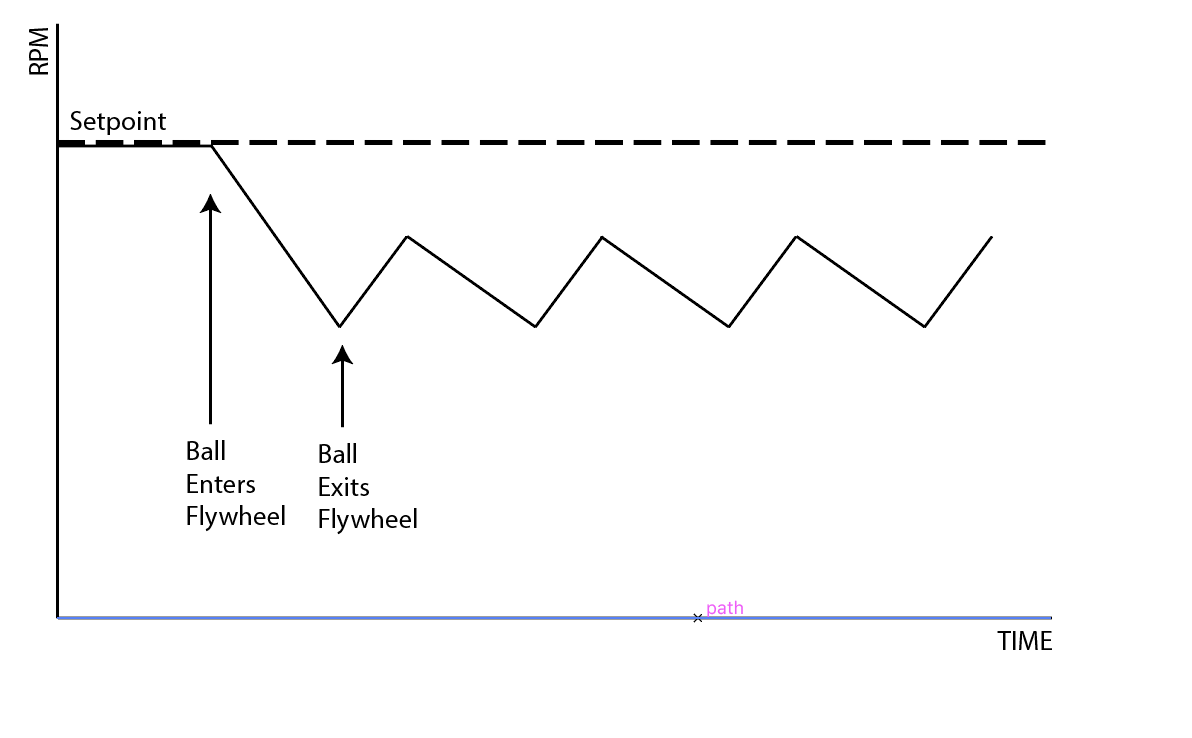
This is definitely better because the balls are consistently exiting at the same speed, however we aren’t getting to where we want to be when we shoot. When this is achieved, we can finally calculate KLoadRatio. To do this, we take the setpoint and divide it by the Lowest RPM, which should now be constant for every ball. This yields a number greater than 1. Now the output of the function looks more like:
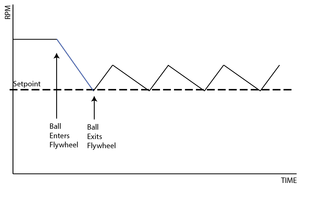
Notice that the steady state is now greater than the set point. This is because it anticipates that the RPM will decrease when a ball contacts the flywheel and it increases the speed before the ball hits so that the speed is correct when it actually is released from the shooter.
Here are videos of the testing we did.
Robot Vision
Today, we found the correct equation for using the camera matrix and distortion coefficients and undistorting an image. We found the equation in this Wikipedia article. This is working pretty well. Now we just need to implement it into the robot code, and it should be done.
We also discussed whether or not the PIXY Camera would be useful for the targets this year. Right now, the current plan is to use the pixy for the gear vision target, but not the boiler. We believe that the low resolution of the Pixy camera would lead to a high error in locating the boiler, and since the margin for error is so small for our shooter prototypes (see Prototyping section of this blog), we need to have a more accurate system. Thus, we resurrected the old vision system using smartphones from last year, and initial tests are promising. We need to tune the OpenCV, but we were able to get it to reliably filter the boiler target:

Also, we refactored the SPI communication driver for the PIXY Camera so that it is better integrated into the codebase and so that it can support multiple cameras.
Autonomous Path Following
Today, we continued work on the autonomous pathing system. We finally got the code to the point where we were able to deploy it to a spare drivetrain and test. We began by tuning the PIDF constants for the drivetrain and setting constants for the wheel radius, drivetrain width, and several pathing parameters. We had to make many several bug fixes and changes to our code, including rewriting the circle function in out AdaptivePurePursuitController class. We also faced several hardware problems, like the encoders falling off and one of the gearboxes breaking.. However, by the end of build, we were able to get the robot to drive along curved and straight segments of the path with a decent margin of error. There is still much work to be done on the pathing system, including improving its accuracy and implementing turns in place.
