
FRC Day 17 Build Blog
Day 17: Prototyping, Drivebase, CAD
Prototyping
Zipper Hopper
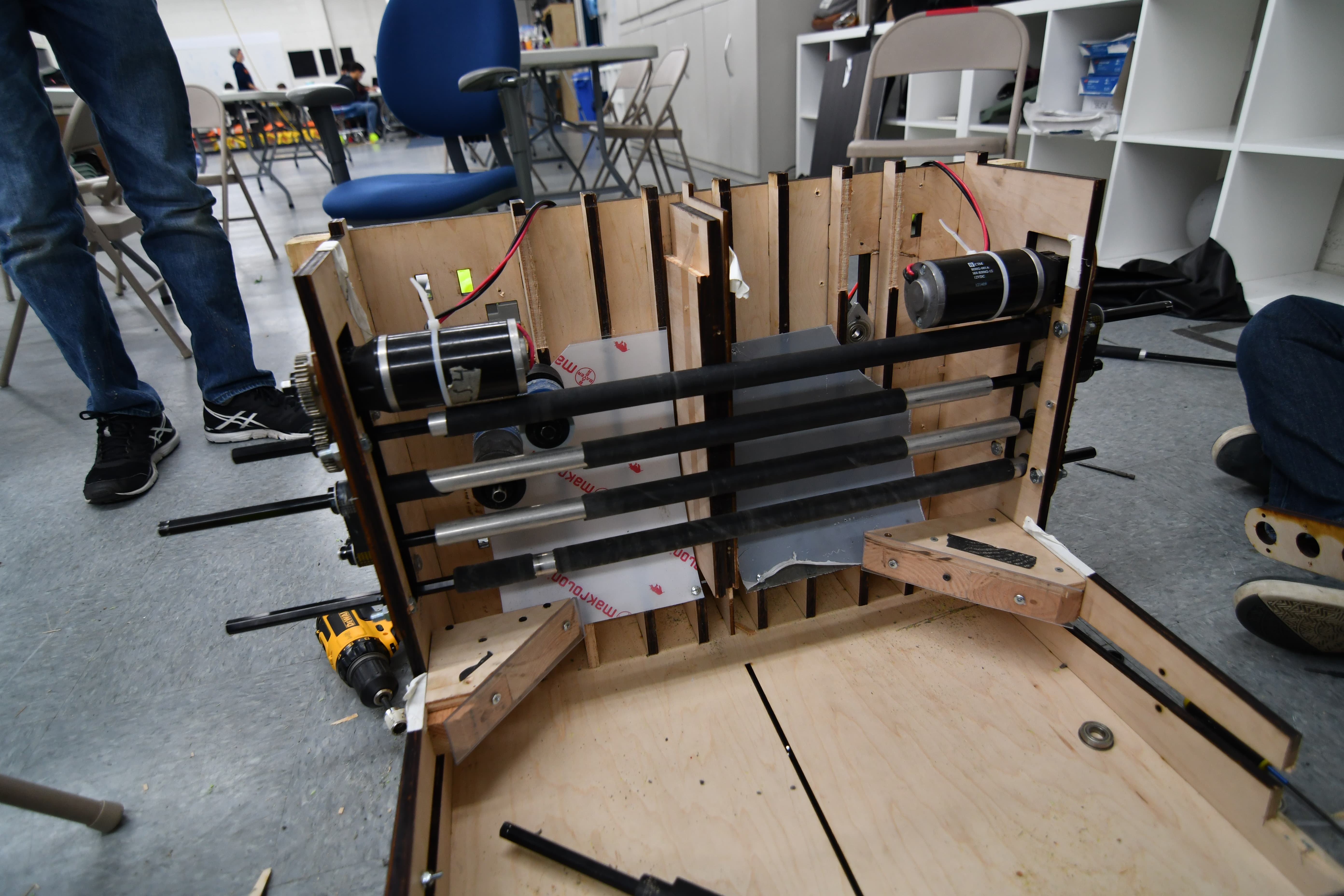
Today was essentially our drop dead date for finalizing 90% of the hopper in CAD. We took our roller design and decided to ship it, with a center to center distance of less than 50mm, as the 55mm on the prototype was too much. While the CAD team was designing, we iterated on funneling methods and found that we could probably use a passive funneling method on the base of the hopper. This passive method worked surprisingly well. We also found that the zip-ties we added onto the rollers did their jobs too well. They acted as small 'fingers' and flung balls. While this is the intended effect, we did not want this at the end of the hopper, and removed the zip ties on half of the prototype. This solution decreased entropy and increased throughput. The design that we have now isn’t the best it could be, but has been designed with adaptability in mind for the future. After deciding on rollers, we continued to iterate on the design with wrapping cloth over the rollers rather than simply belt. We found that this solution has promise and decreases popcorning of the balls. We will continue to iterate on this method next build. We also theorized that if we create a large enough crown on parts of rollers, we might be able to have a significantly faster feeding method with little no change, that could also increase throughput. We will work on this next build as well.
Intake
Today, we finalized the intake prototype after many iterations, and it was CADed into the current robot design. It performs very effectively, being relatively light and simple, but still meeting the goal of picking up every ball in front of the robot at top speed. One improvement that led to the final design today was switching the 1/4" wall surgical tubing on the rollers for 1/8" wall surgical tubing (and adjusting the geometry accordingly), which performs the same but saves a whole pound of weight. Another key change was the ramp, which was changed to 3.5" long rather than the previous 5", and was made intentionally flexible to allow faster intaking and less bogging down as large groups of balls come in simultaneously. The plan for the future is to finalize the intake CAD and to manufacture/assemble it.
Testing:
Gear Intake
Today, we worked a lot on the gear intake. Although previous prototypes had been very successful and gave us a really good starting point, one factor we hadn’t looked into very deeply was the sizing constraint that we would have to work around. In order to figure out the geometry and work out generally how the system would work, we evaluated a bunch of different variables, including changing the bore size for the compression system, as well as modifying the rotating system so that it could package and deploy within the sizing box of the robot. Once we figure out these details, we then began designing the parts in Solidworks. The next step will be to finish the design of the the actual system itself and then look into possible mounting solutions for the rotating system that will connect the claw to the robot itself.
Drivebase
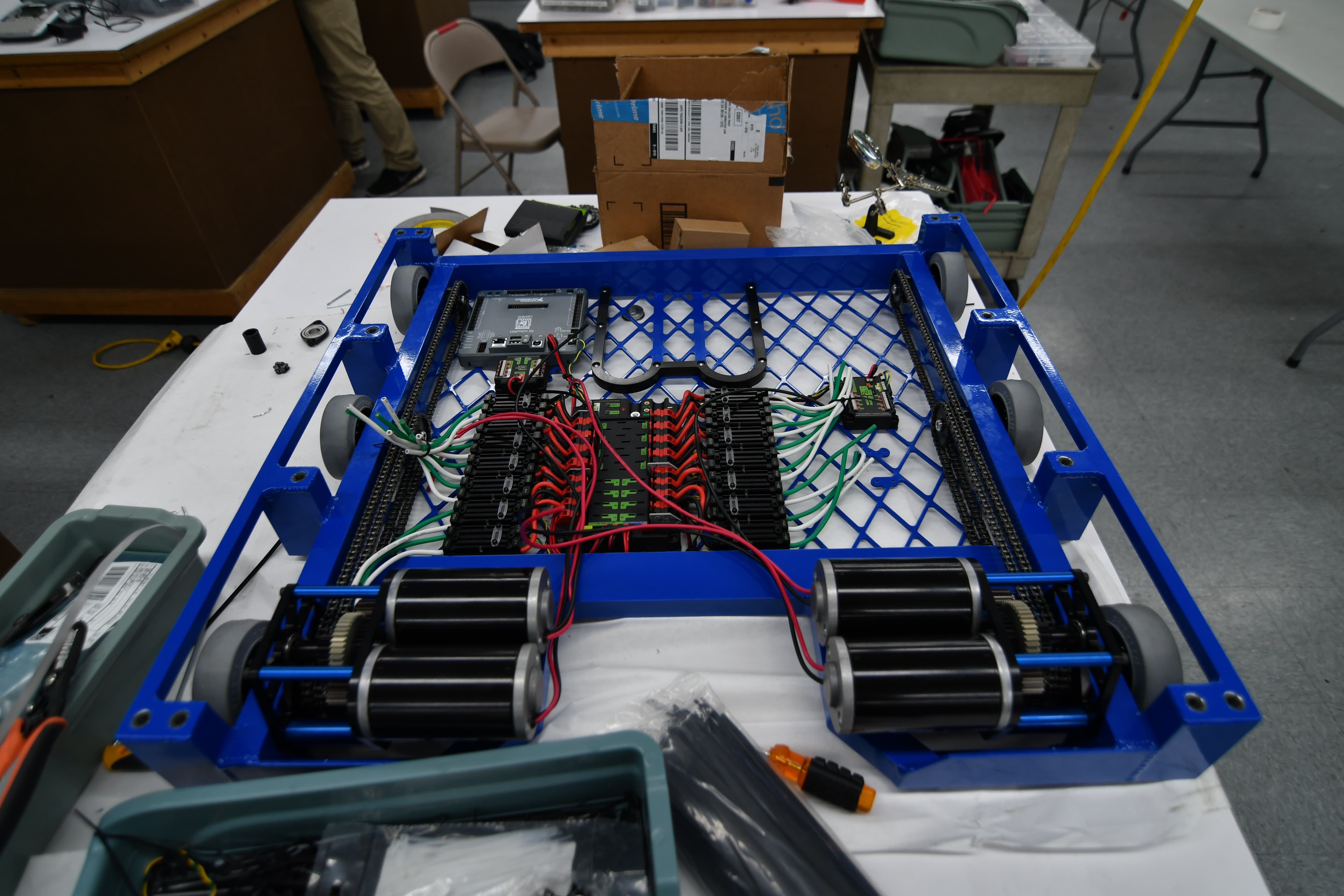
Today, we assembled the drivetrain of the robot including the gearboxes and chain. We finished the drivebase wiring for one robot and had it driving on the field for the first time! We also built and mounted a lasercut delrin battery box. We are waiting on a few last CAD details and a few parts to finish the drivebases of all three robots.
CAD
Today, we worked on the CAD of the hopper conveyor assembly. We are using 10 0.875" OD rollers with a center to center distance of 49.5mm. The conveyor is powered by two 775 pro motors with a 3:1 reduction. It will pivot below the intake pivot along a 0.625" OD shaft before/after the match to change batteries and service electronics. The current plan is to have it latch into place with a pin that goes between the side plate of the hopper conveyor and a .25" plate attached to the inside of the shooter uprights.
Programming
Today, we calibrated all 6 PixyCams and outputted all constants to a java file. We tested this on the roboRIO and it worked really well. We changed the lens of some of the cameras to a InfraRed (IR) lens with a narrower field of view with less distortion, which is better suited for the boiler vision detection. We are working on a distance model that based on the image finds the distance to the object is that image, using the pinhole camera model.. Unfortunately, our calculations are very noisy (fluctuate a lot) and are smaller by an order of magnitude. We have yet to refine our code and calculations.
We also tested out the autonomous routine path code, but the NavX board was running the wrong firmware and didn’t work with our code. We will troubleshoot this issue at the next build.
