
FRC Day 3 Build Blog
Day 3: Progress in Prototypes
Prototyping
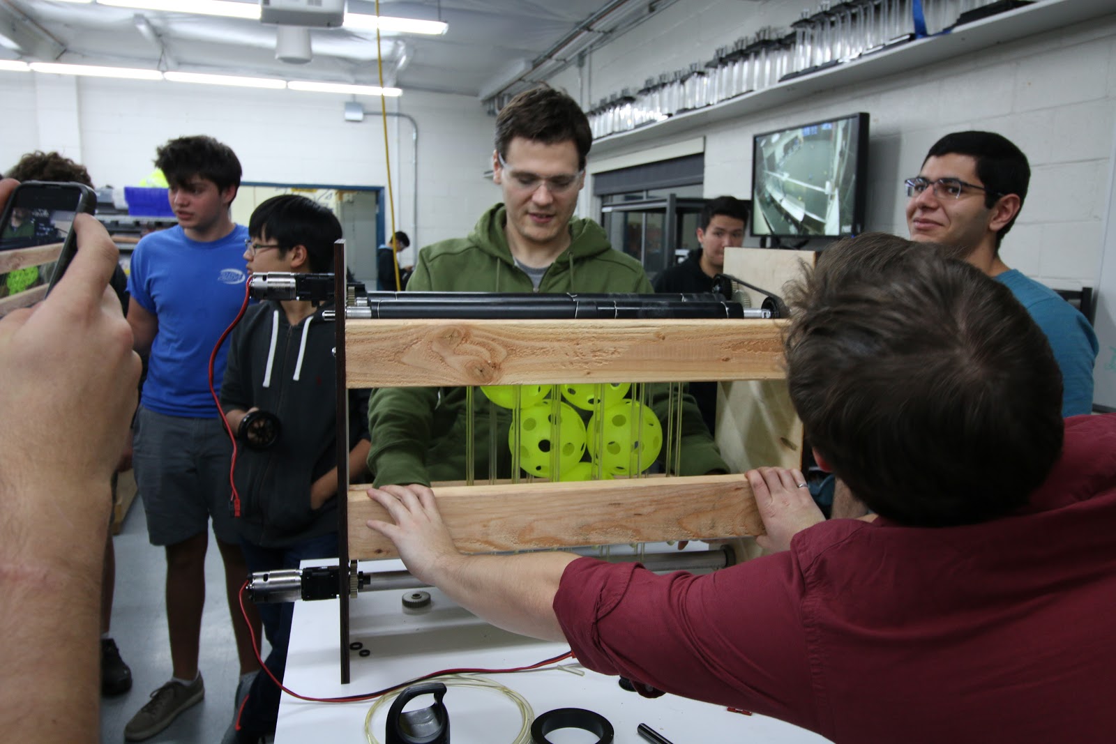
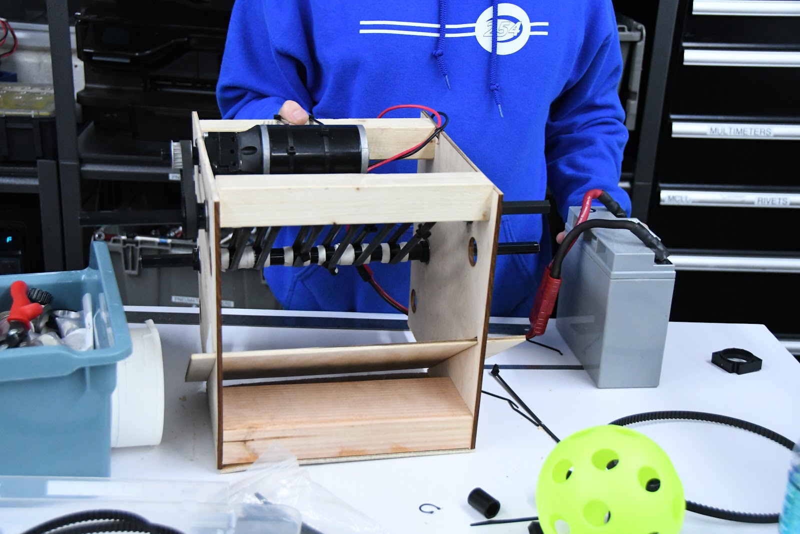
Double Wheel Vertical Flywheel
Today, we worked on assembling the Double Wheel Vertical Flywheel. Taking the parts from last build, we assembled it using the new VersaPlanetary gearboxes and encoders we received. We assembled the flywheel to our previous spec, but we had problems with the gears we had in stock. We changed the ratio in CAD and laser cut a new plate. After doing so, we assembled the flywheel. While the flywheel worked well after changing to polyurethane, the conveyor system failed. Rather than cutting a new plate, we cut a bearing hole and inserted a hex shaft on the inside of the polycord, essentially acting as a tensioner. This worked relatively well, but needs further refinement. We did prove our concept, and will further iterate to better understand how best to integrate our design with the robot.
Testing:
For the Double Wheel Variable Compression Vertical Flywheel, we assembled the majority of the pieces and only need to insert the wheels to begin testing.
Fuel Intake
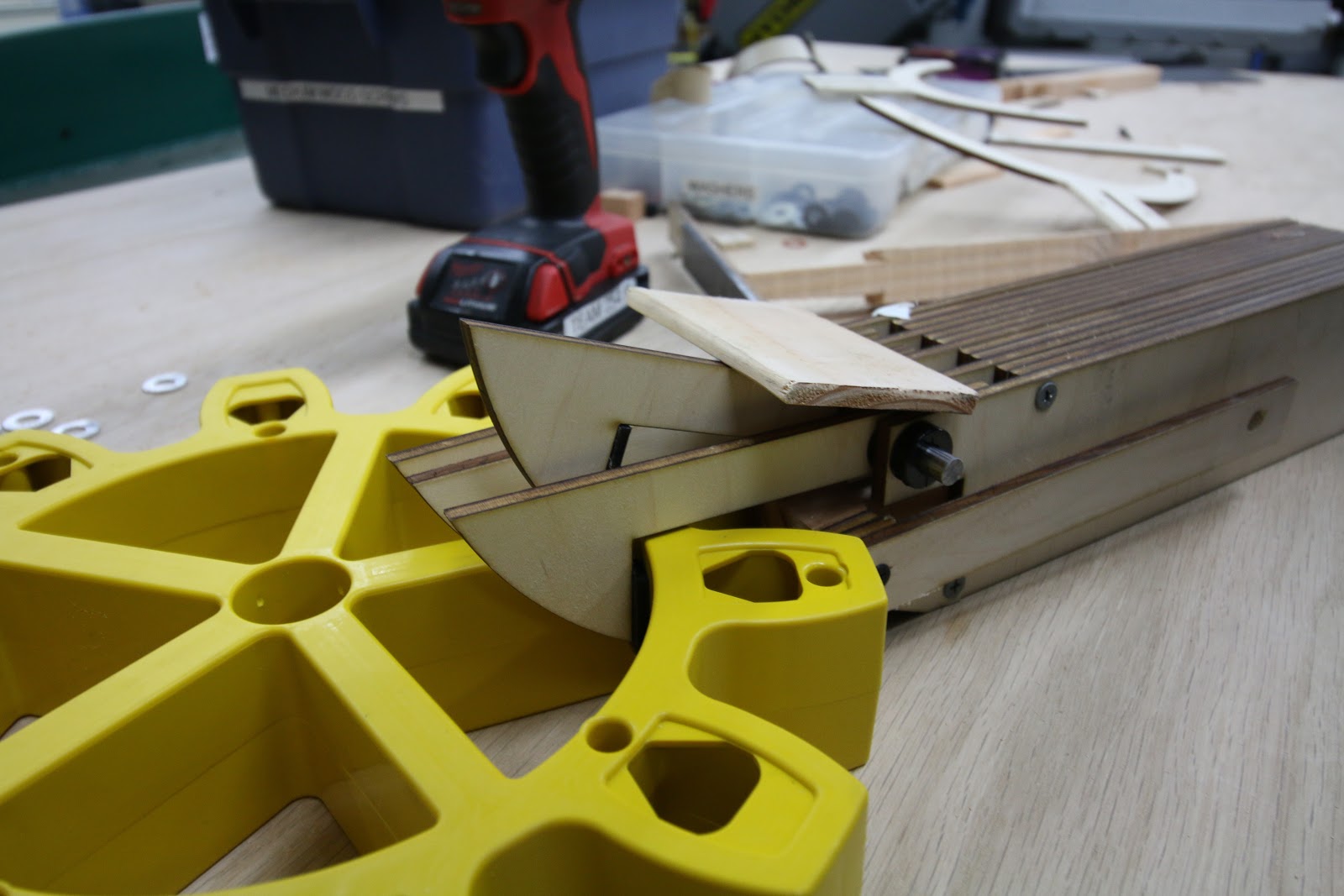
We finished assembly and began testing the belt intake, which was very fast when pulling balls in, but protruded several inches beyond the bumper. We began to design a new intake today, which will be much more compact and will therefore allow for a larger hopper and more room for other systems. This intake uses no belts, and two polyurethane rollers pull the balls up and over the bumper into the hopper. This removes the inefficiency and added complexity of belts, and makes the whole design cleaner and simpler. The intake's design is finished in CAD, but it has not been built or tested yet. On Friday we will laser cut it, finish assembly, and test it to see how effective it it..
Testing:
Gear Intake
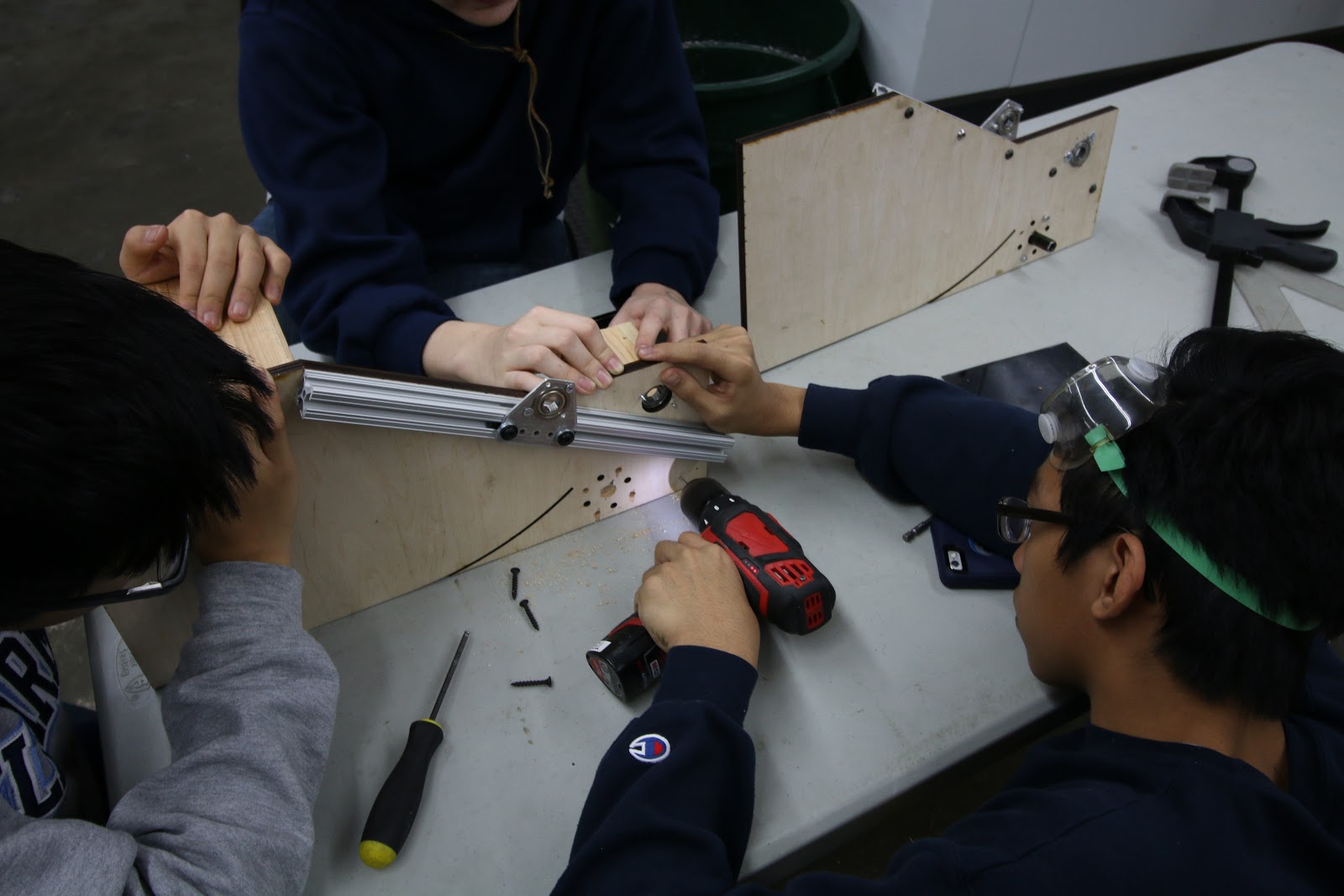
The Gear Intake development process continued today with the construction of a recently CADed design that has an inner slider in order to pinch the gear between the claws and itself. This process was difficult because the .25” plyowood that was used for construction is actually .2”, so the original design needed to be modified slightly so that all the pieces would fit together. Other small improvements involved adding polyurethane strips to the inner slider and the claw so that the whole system grips onto the gear well.
Testing:
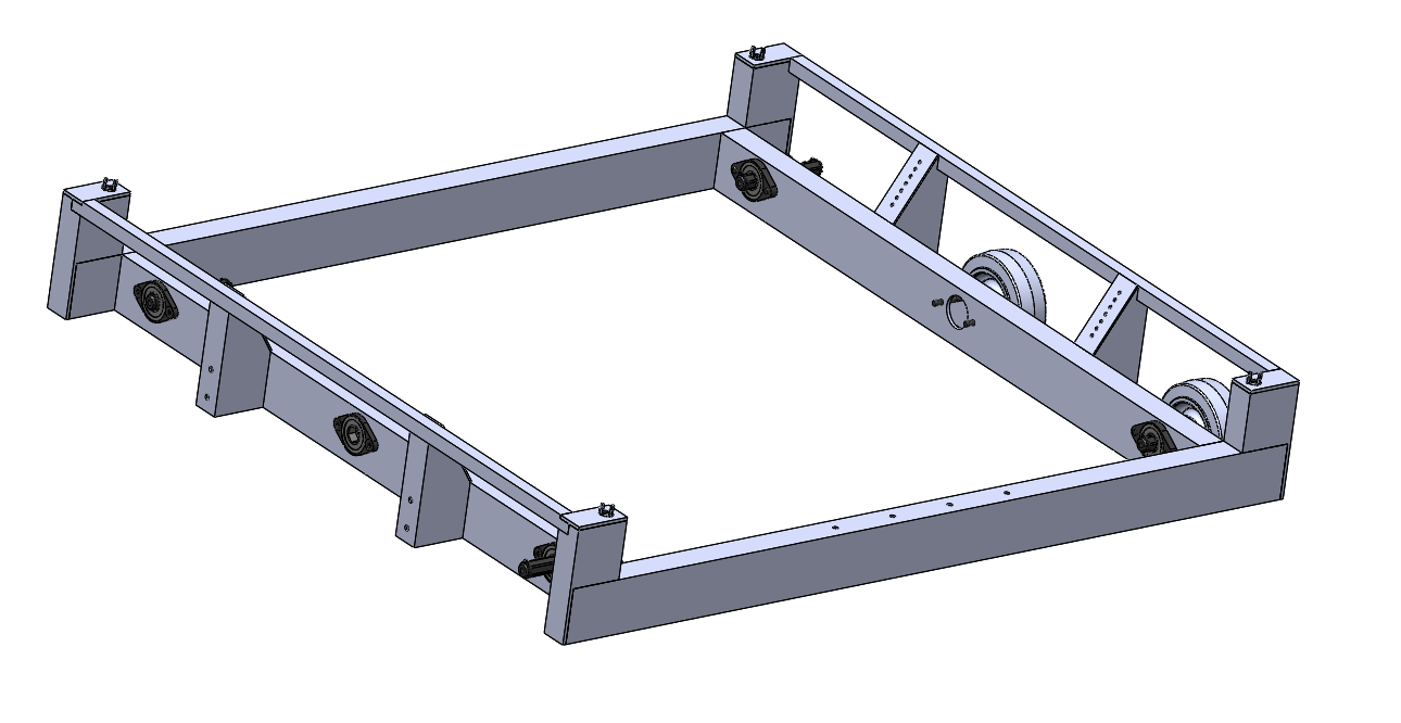
Drivebase
We finished an initial weldment of the general structure modeled after our 2014 robot and the side rails/bearings/housings modeled after our 2016 robot. Taking bumpers and an intake into account, the frame was dimensioned to fit within the 36" by 40" by 24” size limit.
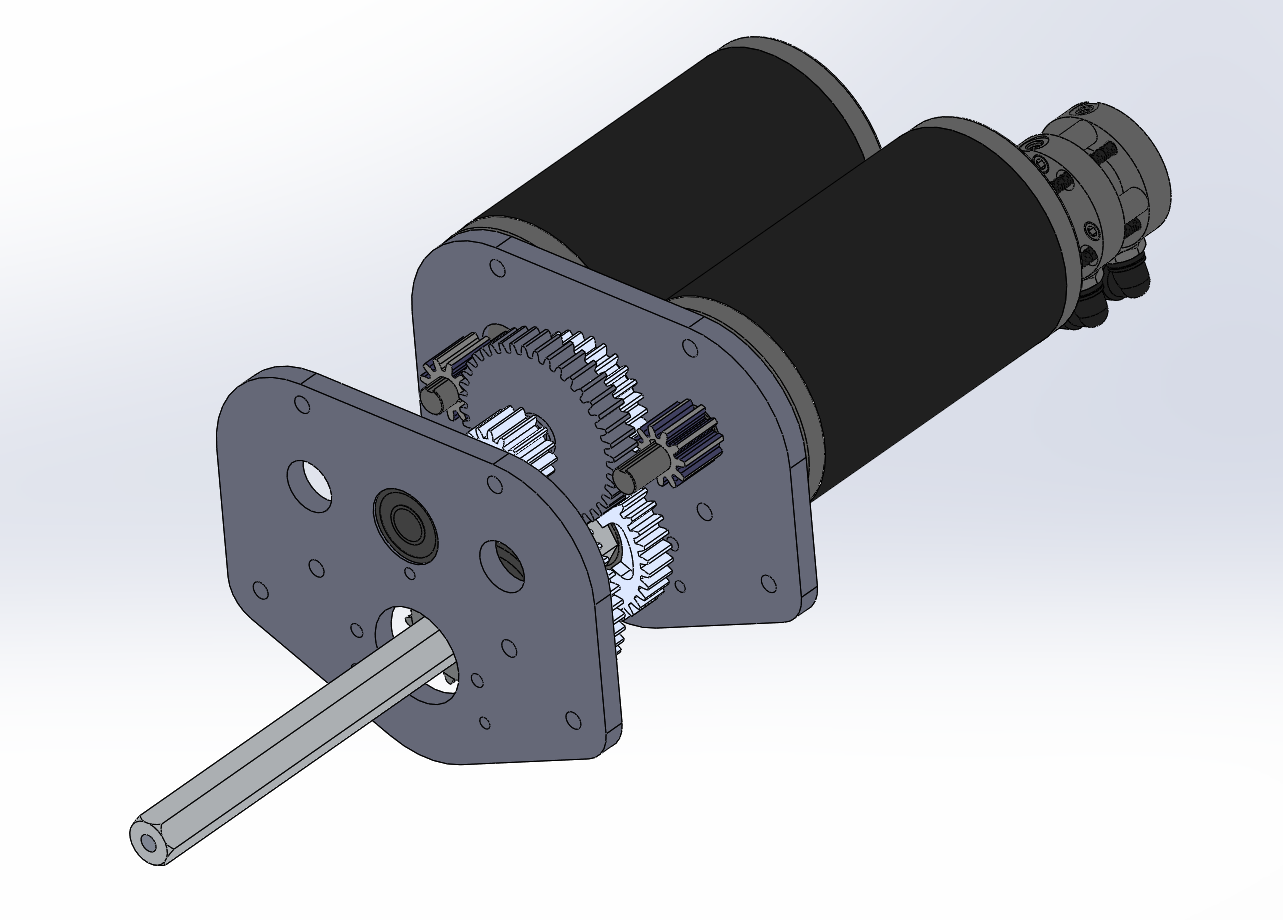
In addition, we designed the drive train gearbox in CAD with 2 CIM motors per side in a 2 stage reduction with a dog shifter and pancake piston to have 2 speeds: low gear for pushing force and high gear for maneuverability. With the design almost done, we only have to add spacers, intermediate shaft, standoffs, screws and nuts, retaining screws, and pocketing to the CAD (members can access the design from pdm under the name 254-17-A-0300 Gearbox if you want to see or help design it).
Climber
Today, we designed and began to build prototype mechanisms for climbing the rope. The prototypes for actually holding onto the rope included variations combs with differing spacing. We began working on a standard mount for each type of prototype climbing roller. We decided to use a VersaPlanetary gearbox in our build, using a gear ratio of 1:90 to heavily reduce the rpm of the motors from ~18,000 RPM and increase torque to ensure the robot could lift itself. We then assembled the multi-stage gearbox, attached the motor, and soldered the battery leads. Lastly, we began the process of building a frame and prepared the parts to completely assemble the mounts next build.
Programming
Control Board
On Wednesday, we met up and worked on control systems for recent prototypes and we also continued developing pixycam communication. We added three talons to the prototype board to support the growing complexity of prototypes.
Robot Programming
With a prototype board ready, we added feed-forward PID control to our two-roller shooter prototype. PID is a control loop that keeps a constant motor speed, allowing us to effectively test the shooter prototype.
We also rewrote a majority of our code using elements from last year’s code, to avoid re-inventing the wheel. The new code is far more scalable and efficient. In particular, we implemented Loopers, a structure that runs code extremely fast, and compartmentalized our code into the various (potential) subsystems on the robot. We also discussed code conventions to ensure uniformity in the code down the road.
However, we had issues with compiling and deploying the code due to issues with the motor controller driver. We’re resolving those issues down the road.
Camera Connectivity
We worked on camera connectivity, finishing a testable version of an SPI driver built on WPILib for the RoboRIO. Previously, we built a native library that allowed us to communicate with the PixyCam over USB and wrote a JNI wrapper to let us invoke the native code from Java, but today we encountered issues when connecting to a physical PixyCam. Rather than debugging the USB connection, we decided to ensure that we could build a reliable SPI driver first, as we are confident that we will be able to communicate with the camera over SPI. Though a USB interface would be optimal, it is significantly complex and we plan to work on that functionality once the SPI driver is confirmed to work as expected.. We added a new pinout to the PixyCam and connected it to an old RoboRIO board for testing. To help with testing, we connected the PixyCam to a computer and trained it to recognize the yellow game balls. In the upcoming builds, we will proceed with testing our SPI driver with an old RoboRIO so we have a working method of connection for this year’s code.
