FRC Day 33, 34, & 35 Build Blog
Days 33, 34, & 35: Preparing for Competition
Gear Grabber/Driver Practice
We worked with the drivers over the weekend, doing basic drills like gear cycling, in order to become accustomed to driving the robot prior to the SFR Competition. We started the day by iterating on the floor for the gear grabber. The floor pickup for gears still needs work as it is inconsistent at picking up the gears when we drive into them. The polycarbonate knife edge was not as smooth as the prototype. There was a small edge on the actual version which was causing problems, so we sharpened it. After iterating on it, we then mounted it, and set ourselves on solving the jackknifing. We realized the best solution for this would be to redesign it, so Andrew and Mani are working on a new CAD. Meanwhile, the group worked on iterating on the length of the polycarb. We still have work to do before we finalize the design.
Bumpers
The major problem we were trying to solve was that the bumpers were too low. This was because the mounting solution uses C-channel brackets that go around the bumper supports and are supposed to sit flush to the underside of the little 1/2 x 1/2 bumper rail. But, what we didn’t realize is that the rail actually has a weld bead under it so the brackets could not go up high enough. This made the bumpers too low to the ground. To fix this, we removed a couple staples and pulled back just a bit of fabric on one of the practice bumpers so we could remove the brackets without actually remaking the entire bumper. We used the mill to make the brackets shorter, so they can move up and avoid the weld. We also used the drill press to add a new hole so they can align to the holes already drilled in the robot. This works pretty well, but some concerns are that the bumper is now too high and lifting the intake up, preventing it from going down far enough to have good compression on the balls. As of now, the intake is working fine. We still need to mill down all the other brackets, and we talked about making new ones and getting them anodized for the competition bumpers. The red comp bumper still needs fabric, and the blue one should have the fabric removed.
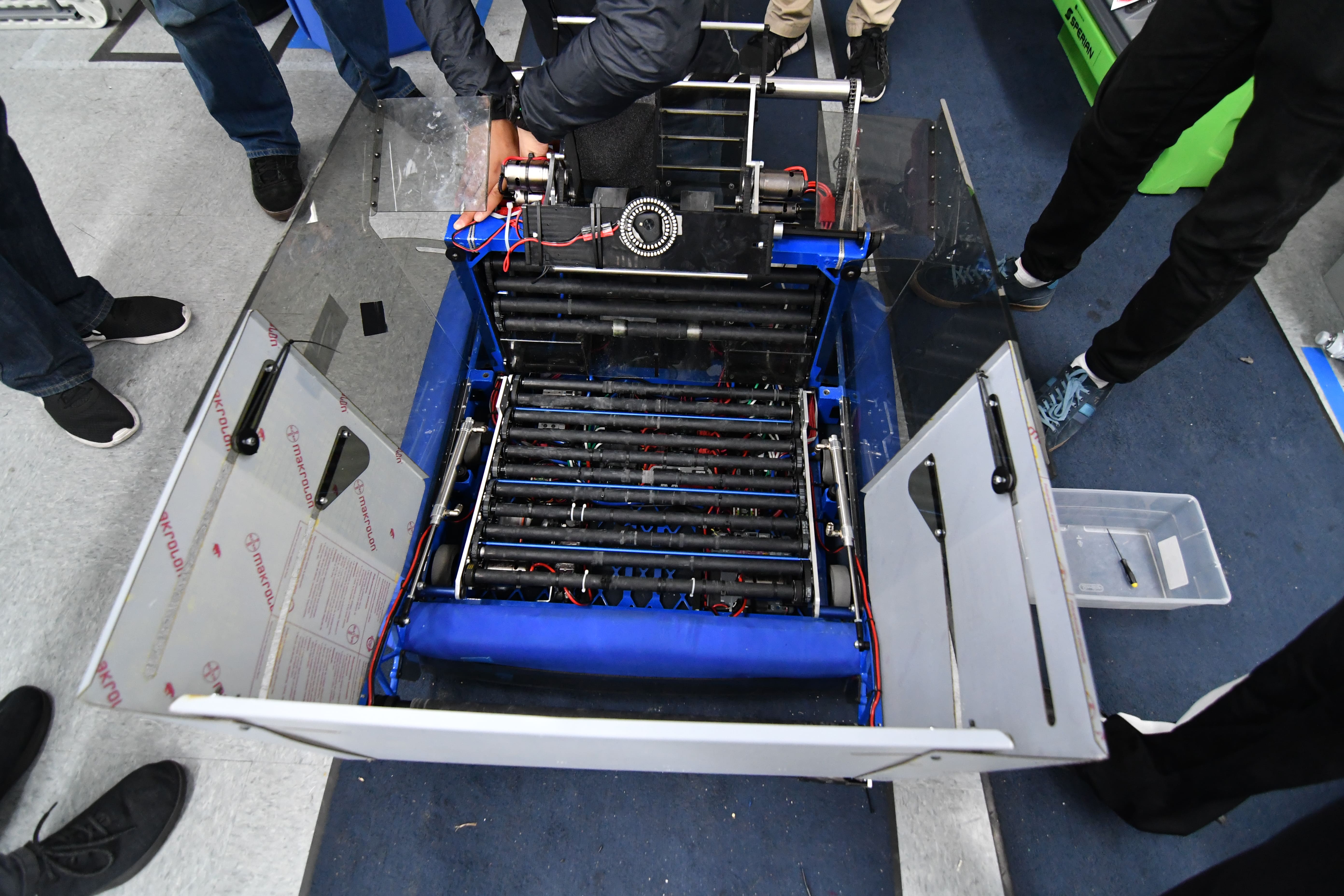
Hopper
Over this weekend, we worked on the hopper redesign. After some initial tests, we found that perhaps preventing the hopper from expanding sideways in the front expansion might add rigidity and strength to the hopper. To do this, we tested by bolting the front sliders to the hopper to prevent them from sliding. After testing, however, we found that intake by actuating the field hopper became difficult as the decreased width of the hopper prevented the balls from coming into the robot. To accommodate this, we redesigned the hopper in CAD so that the top will slide out vertically while the bottom pivots about a fixed point that torques the flexible polycarbonate. We also started the CAD of the new hopper floor for SFR which has the top rollers and wedges and a center to increase our ball throughput. We started the construction of the wedges on the hopper floor. After some brief testing, we CAD-ed this out. We will begin manufacturing on Monday.
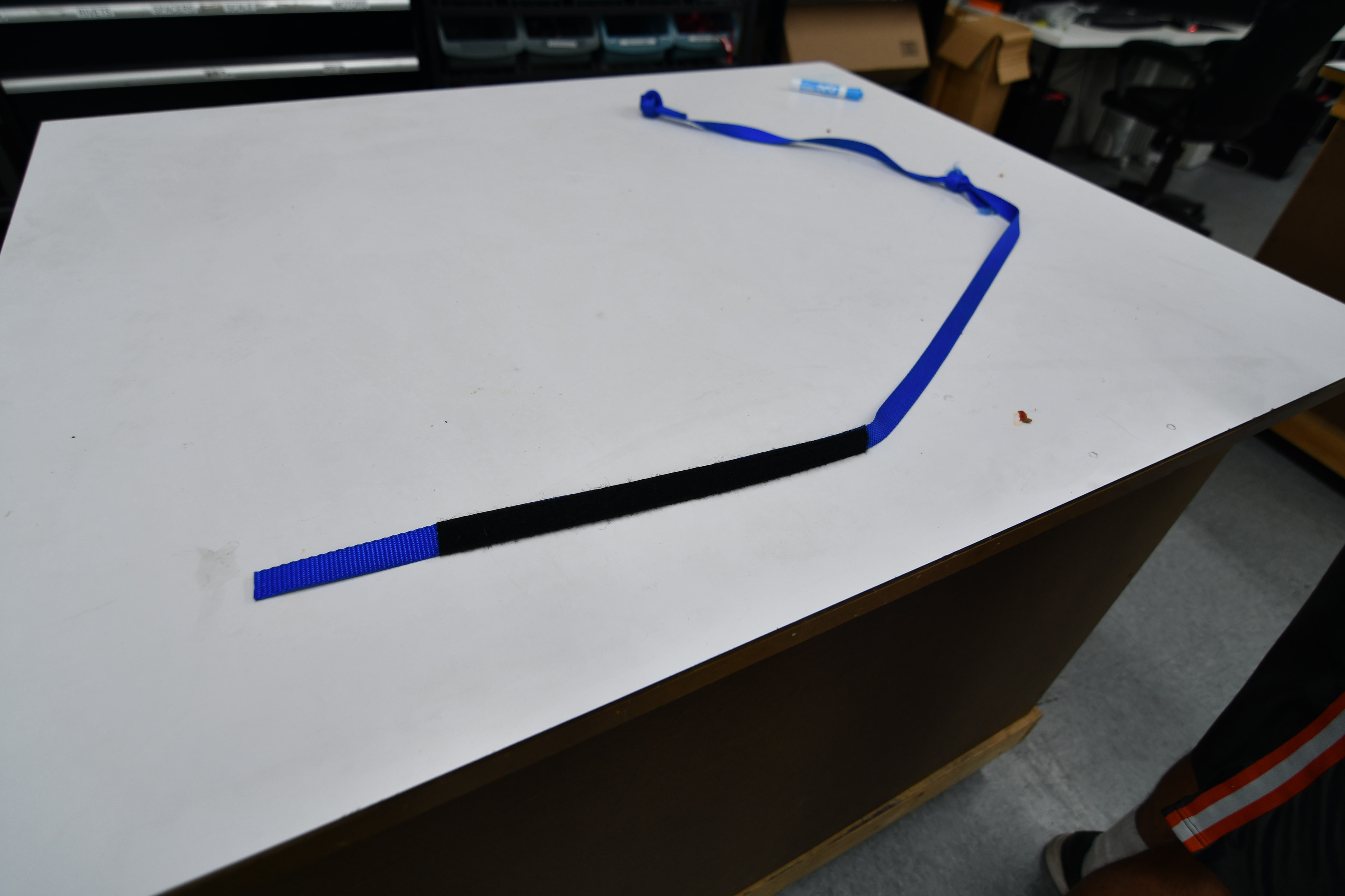
Hanger Rope
This weekend, we received the 3/4” ratchet strap climbing ropes with the sewed on velcro. We tested it by pulling on it and rubbing it at corners in order to see distressing. The rope was then tested using the rope climber on the practice robot but the lack of stretch/slack made it hard to latch onto. In the near future, the rope team will attempt to plan out elastic placement on the rope.
LED Light
We wired up a MOSFET to control the switching of the LED light, located on the front of the robot, by having a voltage signal sent out from the relay port of the Roborio. It allows the drivers to see better when having to place a gear without the light blinding them.
Programming
Autonomous Program
Today, we worked on creating a reliable 40 kPA autonomous mode. We decided that previous autonomous modes that used complicated S curves to swerve into the hopper were too inconsistent, so we settled for a new, much simpler mode. But, at the end of the night, we had a working auto mode that deployed the intake, rammed into the hopper head on, waited a few seconds for balls to pour in, then aimed and fired the balls into the goal. We continued to improve the efficiency of this autonomous mode until we had it begin shooting around 6.3 seconds or less. We needed the autonomous mode to begin shooting as early as possible because there is around a 5 second delay between scoring a ball and having the scoring system pick it up. Because of this, any balls shot past 10 seconds will probably not be scored during auto.
We continued revising our robot's autonomous routines, and we were able to drive to the hopper and trigger it, receive a payload of balls, and fire into the boiler.
We also worked on a live data plotter that could plot robot data much faster than SmartDashboard. Various subsystems, such as the drivetrain, simply push data to a server, which pushes data to a grapher website on the driver station. This utility will be useful for tuning drivebase and shooter PID, as well as other programming tasks.