FRC Day 4 Build Blog
Day 4: Iteration of Prototypes
Prototyping
Double Wheel Vertical Flywheel
As we proved this flywheel could attain a high throughput, we transitioned today to begin testing different wheel types and compression as well as the conveyor system. In the process of setting up the next prototype, we found we lacked enough polycord pulleys, and machined more out of some delrin stock. We scavenged the 3:1 VersaPlanetary gearboxes from our previous prototype. While we did not have enough time to finish developing the prototype, we have all of the pieces and can finish it quickly tomorrow.
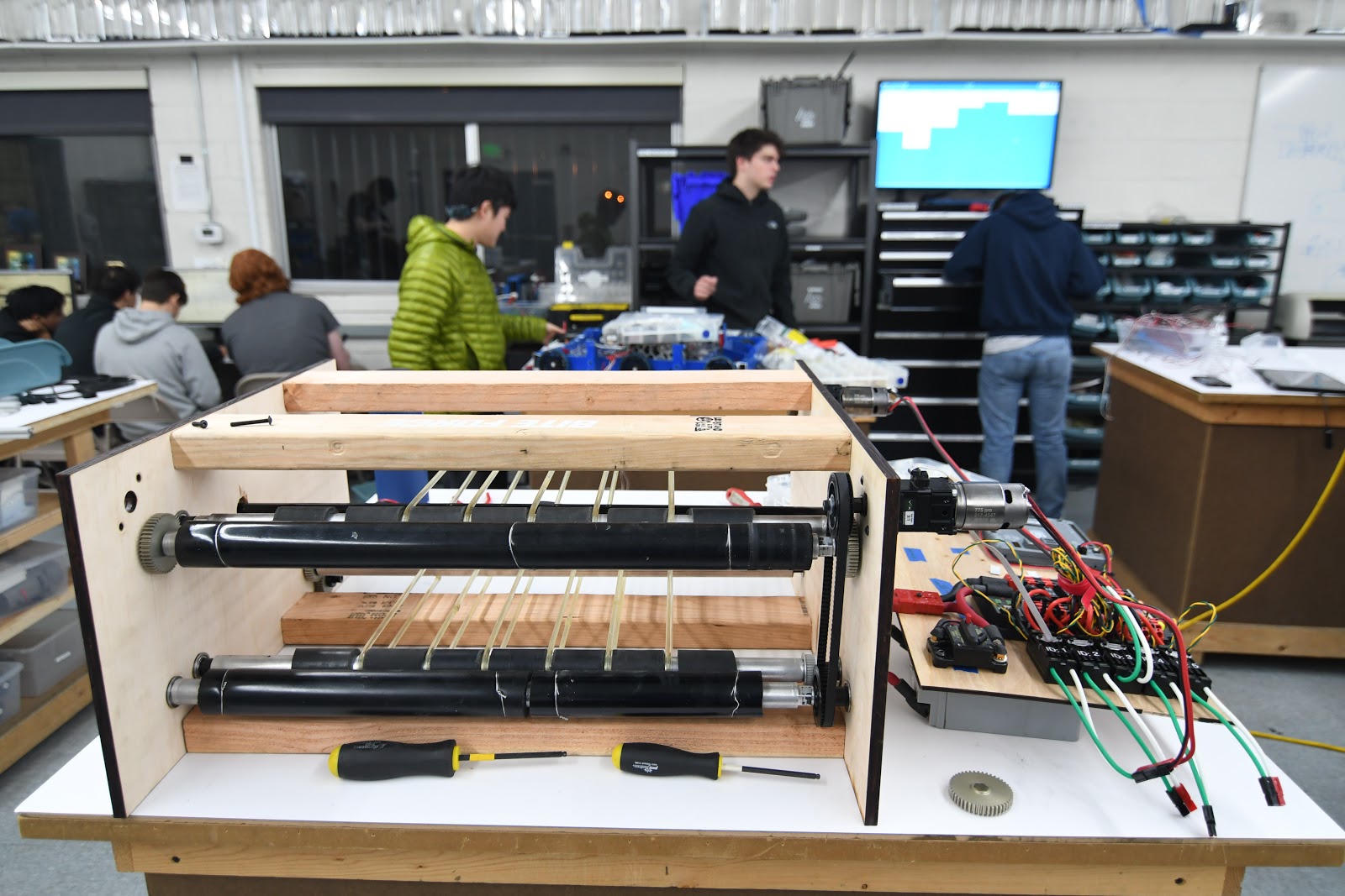
Fuel Intake
Taking the intake design from yesterday using two polyurethane rollers, we laser cut and assembled it, discovering that while it was able to pull balls up and over the bumper, the balls sometimes got stuck. the compression was too little on top of the bumper and it sometimes got stuck. The compression seemed to be too little at the top of the bumper because we didn't account for the bumper compressing alongside the ball, so we went back in CAD and redesigned the geometry of the upper roller to have increased compression. We are still in the assembly stage of the new and improved version, so we will see tomorrow how well it works with the improvements. For the future, we still have to see how effective the new design is before we CAD the real intake for the robot, but it is likely that this will be the preferred design because of the simplicity of having just 2 rollers.

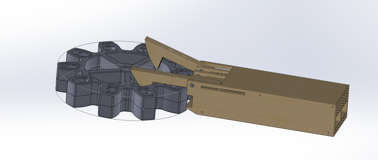
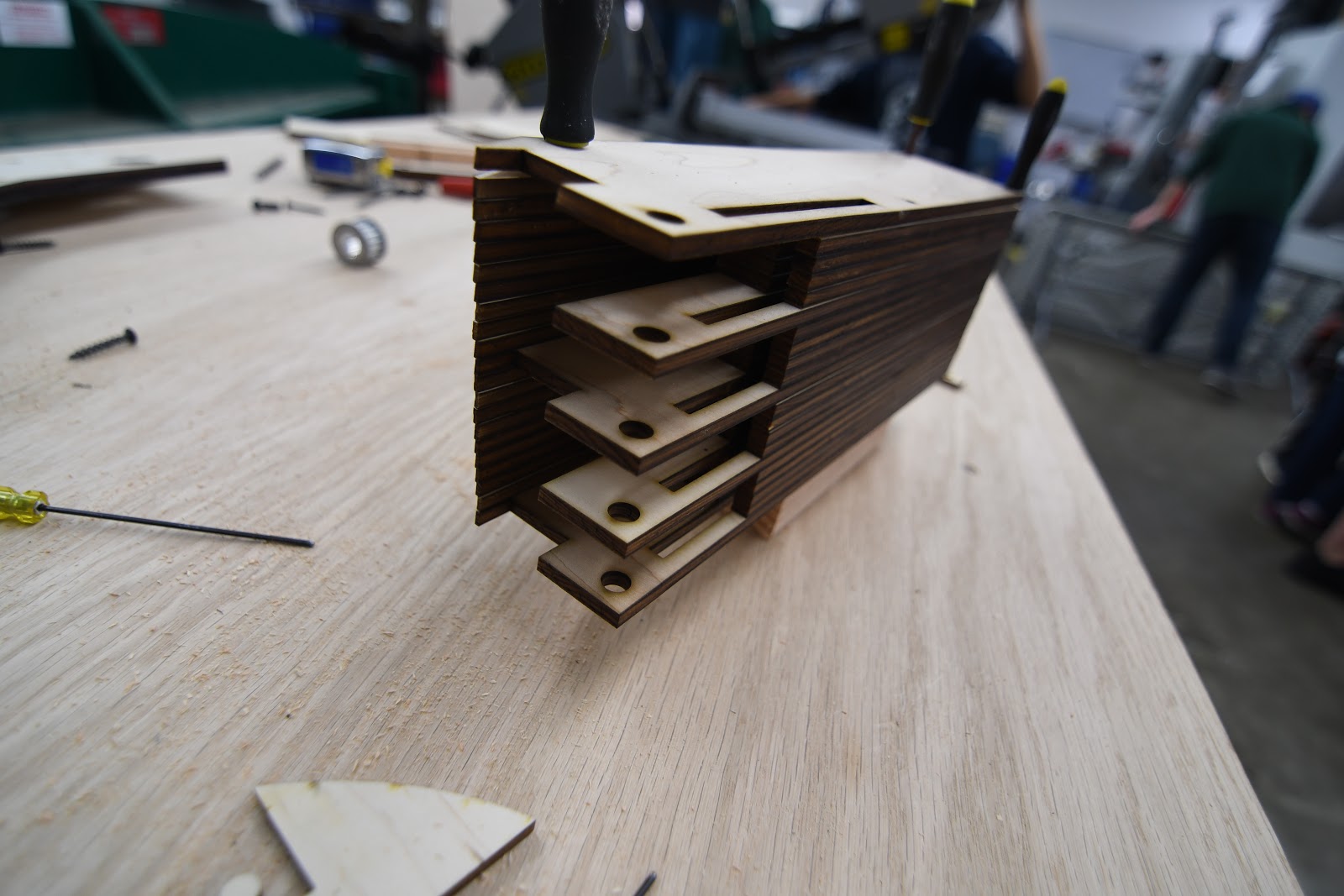
Gear Intake
Throughout the course of the build today, we worked on constructing the 3D CAD design that one of the students made the day before. This worked out well because we were able to get the whole thing laser cut and fully constructed relatively quickly. Although this design seemed to be very similar to the previous version, a new key feature was added: A locking system for the claws while they are grabbing onto the gear. Although we were not able to fully test the design today, these improvements should theoretically allow us to manipulate the gear in 360 degrees, something we were not able to do previously. At the build tomorrow (Saturday), the main focus will be to finish building the prototype and look at potential ways of packaging the design give the tremendous size constraints presented.
Drivebase
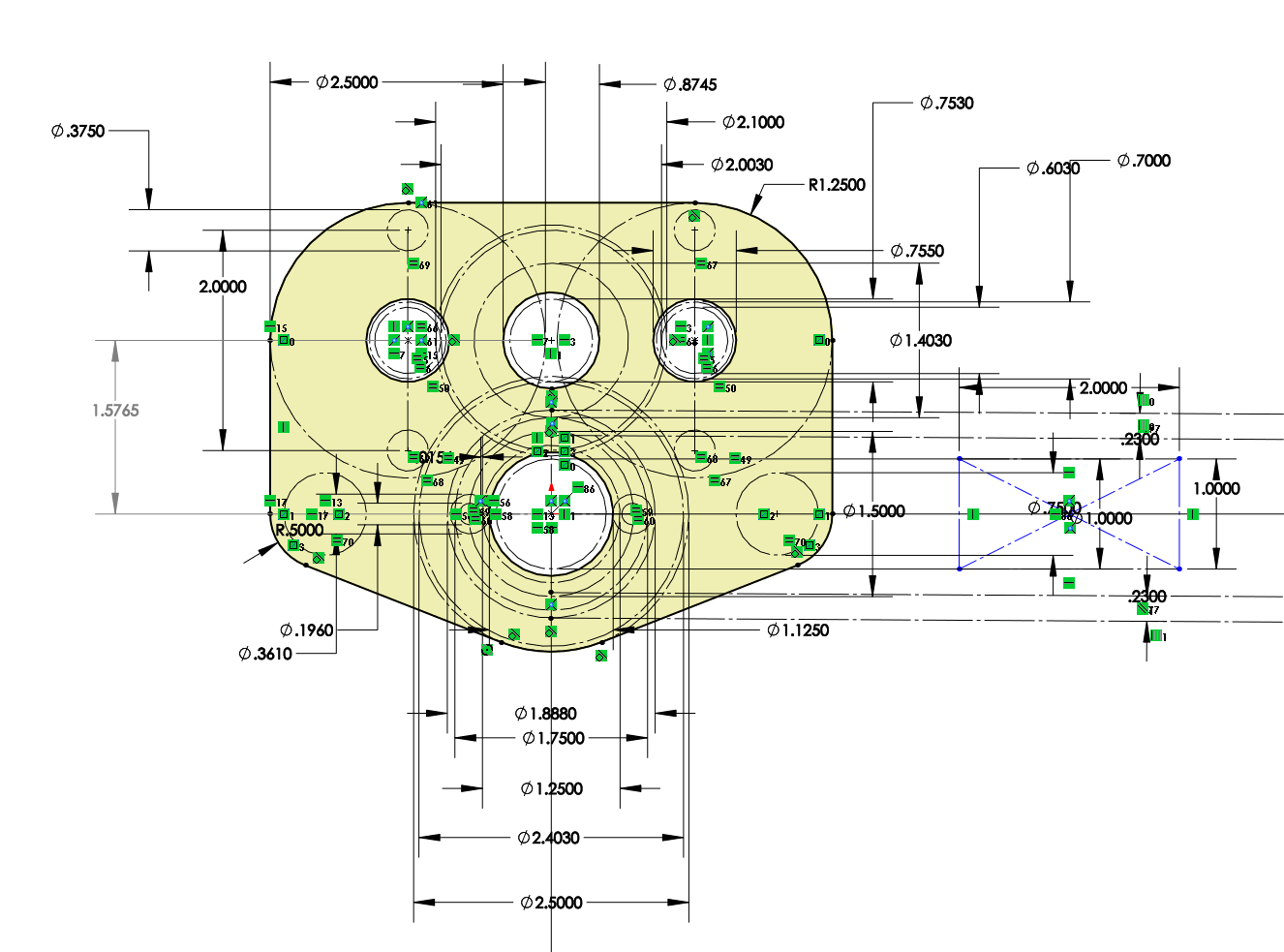
Today we finalized the CAD Design for the Drive Gearbox, which is now almost ready for manufacturing. We started by pocketing the gearbox plates, a method used to reduce weight while maintaining the structural integrity of each plate. Our two gear ratios are 15:48 and 28:35. We decided to have a two stage gearbox with a dog shifter in anticipation of heavy defense, allowing the robot to have speed and maneuverability based on the situation. We also added spacers, an intermediate shaft, and designed a new front gearbox plate. Through the design of the gearbox plate, we were able to save 0.04 pounds in a game where the robot weight is inversely proportional to its speed.

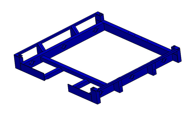
Regarding the drivebase weldment, We modified it to have a cut out in the back. The gearboxes will sit in the two cutouts in the back corners and the gap in the middle will be for a gear intake mechanism..
Climber
Today, the rope-climbing project finished prototyping a “comb” to grab the rope as well as housing to connect the comb to the robot for testing. We completed the comb by measuring the diameter of the string to find the distance between each prong of the comb. After this, we cut these parts out and tested it by ensuring that rope with knots would successfully hook onto the comb. Besides this, we also created the housing by attaching a VersaPlanetary enabled motor to a wood structure. We then connected the motor to a shaft by using gears and bearings. At this point, we just need to attach the comb to the shaft in order to finish assembly and begin testing.
Programming
Camera Calibration:
After manually calibrating one camera with limited success, we decided to automate the process to make calibration quicker and more accurate. The goal of the project is to have the OpenCV calibration code to read the camera input automatically so that we can see what angles will work for calibration before we take the picture. Today we downloaded all the necessary software needed to run the calibration program (OpenCV, Eclipse C/C++, MinGW, etc.); however, we did not finish this. Needed for next build is to set up Eclipse with a compiler and Download all the premade libraries for OpenCV. After that, we can edit the code to make it more user friendly, by having it connect directly to the Pixy Camera, and improve calibration.
Camera Connectivity:
Today, we deployed multiple test programs to an old RoboRIO to test our serial driver. Unfortunately, we ran into many issues early on. We then created another program to dump raw SPI input data to attempt to diagnose the issue: we noticed that we were only receiving null bytes (0x00), perhaps due to an SPI protocol error. We found that this occurred because the SPI connection hardware had a loose contact issue between the RoboRIO’s pins and the header pinout; after this was fixed, we received (0xff) bytes. Unfortunately, even after attempting to replicate the protocol according to the description, we could not get the PixyCam to send us anything other than (0xff), which was oddly not documented in the protocol information page. However, we suspected that the issue may stem from WPILib’s abstraction of the SPI interface itself; thus, we plan to implement a PixyCam SPI driver in C/C++ based on a low level library that accesses the serial port directly. In addition to working on SPI, we also worked on our `libpixyusb` interface, attempting to run the sample program. Unfortunately, we received an error about a failure to transmit/receive data over USB; we traced down the issue in the libpixyusb source code to the low level USB handshake. Getting `libpixyusb` to work reliably on the RoboRIO will likely be extremely difficult, possibly even requiring custom drivers and a kernel patch; the exact same code works as expected on an Intel x86 laptop, but when cross-compiled onto a RoboRIO with the FRC C/C++ toolchain, it encounters this unexpected error. After evaluating the pros and cons of both methods of connectivity, we decided to continue to pursue SPI rather than USB.
Robot Programming
Last workday, we tried deploying robot code to the RoboRIO but ran into problems deploying the code due to conflicting libraries for the CAN Talon motor controllers. After removing the conflicting drivers, we were able to successfully deploy the robot code. These changes are reflected in the latest commit on Github.
We then successfully deployed the code for the shooter prototype to the RoboRIO, but faced problems with maintaining a constant RPM. We used a basic feed-forward controller, which should set a near-constant RPM, but we measured drastic fluctuations in the RPM. We hypothesize that this is because the encoder is returning data at a different rate than the robot is running, leading to discrepancies in the measured RPM. To fix this, we will try connecting the encoder directly to the RoboRIO’s digital inputs instead of to the CAN Talon.
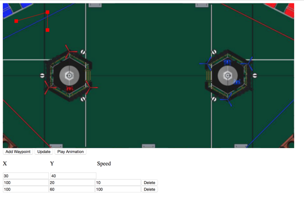
Waypoint visualizer:
We worked on an autonomous mode path simulator. The app lets a user enter waypoints and speeds and plots out a path that the robot will take. The app also supports animating the robot's movement. We also worked on implementing a radius feature into the program that would allow the robot to round corners. This app is a vast improvement over the current method of programming paths which require trial and error. With a helpful web interface, we will be better equipped to plan auto routines before we even test them, which allows us to develop before the robot is built. It’s not done yet, but we have made a lot of progress: