
FRC Day 5 Build Blog
Day 5: Strides in Prototyping and Testing
Prototyping
Shooter
Today we worked on assembling and improving the shooter. After assembling a plethora of VersaPlanetary gearboxes, forming polycord, and machining new hubs for the flywheel, we managed to assemble the prototype. After testing it, we found the real world version to have varied from the CAD, and the compression on the flywheel to be too much. We recut the two shooter side plates to allow for more reasonable levels of compression. We then hooked the prototype up to a mock drivebase and speed controllers. When we tested it, we found that the shooting was inconsistent, most likely due to dead space between the feeder and the flywheels. We tried killing one side of the feeder and changing to a fixed plywood side to lower the variability. While the variability was removed, the spin increased so this plan was immediately scrapped. We then tried to add a makeshift barrel, around 6 inches in diameter and in length. This barrel significantly increased our shooting accuracy. Later, we will have to choose whether or not to have a wide shooter or multiple separate flywheels.
Fuel Intake and Hopper
Today we made great progress on the intake and the hopper. We assembled the updated design from yesterday, and it while it was better (faster, more balls made it over the bumper), we still had the issue of some balls becoming stuck in a "dead zone" and not fully clearing the bumper. To fix this, we decided to try putting 8 thick zip ties on the top roller with about two inches of uncut length, in order to kick the balls up and over the bumper when they got stuck. The results were fantastic: the intake overall worked much faster and balls never got stuck anymore. It seems like this is close to the design that will be implemented in the real robot later on.
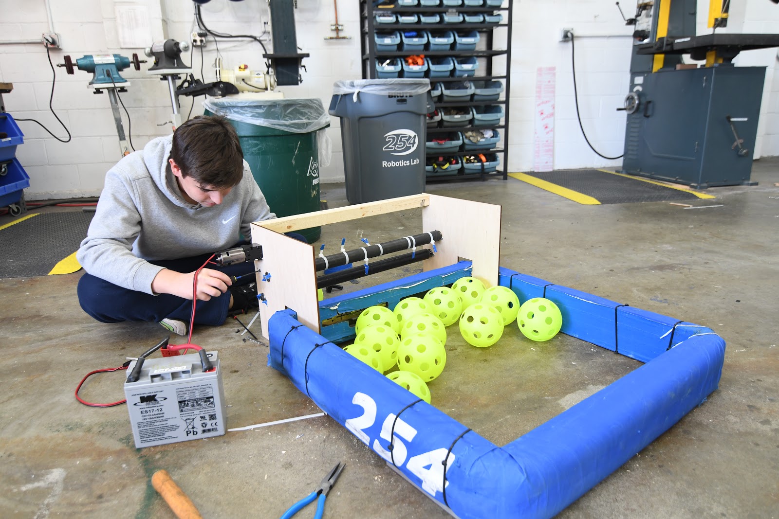
After thoroughly testing the intake, we began work on a prototype hopper that would sit directly behind the intake and hold about 150 balls. This prototype has a sloped floor, which will help funnel balls to the back of the robot so we can continue to intake efficiently and feed into the back conveyor belt that will lead to the shooter. While the hopper was fully assembled and ready for testing, we did not get a chance to try it on the practice drivebase because it was being used for the shooter prototype. For the future, we will test the combination of the intake and hopper, and continue iterating those designs. We are also considering prototyping a hopper with a powered conveyor belt floor, to agitate the balls and feed them towards the back even faster.
Testing:
Gear Intake
Today’s build was essentially a continuation of what we did yesterday. We finished putting together the pieces that were CADed previously and fine-tuned the claw system so that it could consistently pick up gears and manipulate them in 360 degrees. One special feature of our design is that, even if one claw is out of position, the locking mechanism is still able to prevent the other individual claw arms from moving around. Although this design works extremely well as it is, the next step will be to condense it significantly so that it can meet the size constraints of the robot.
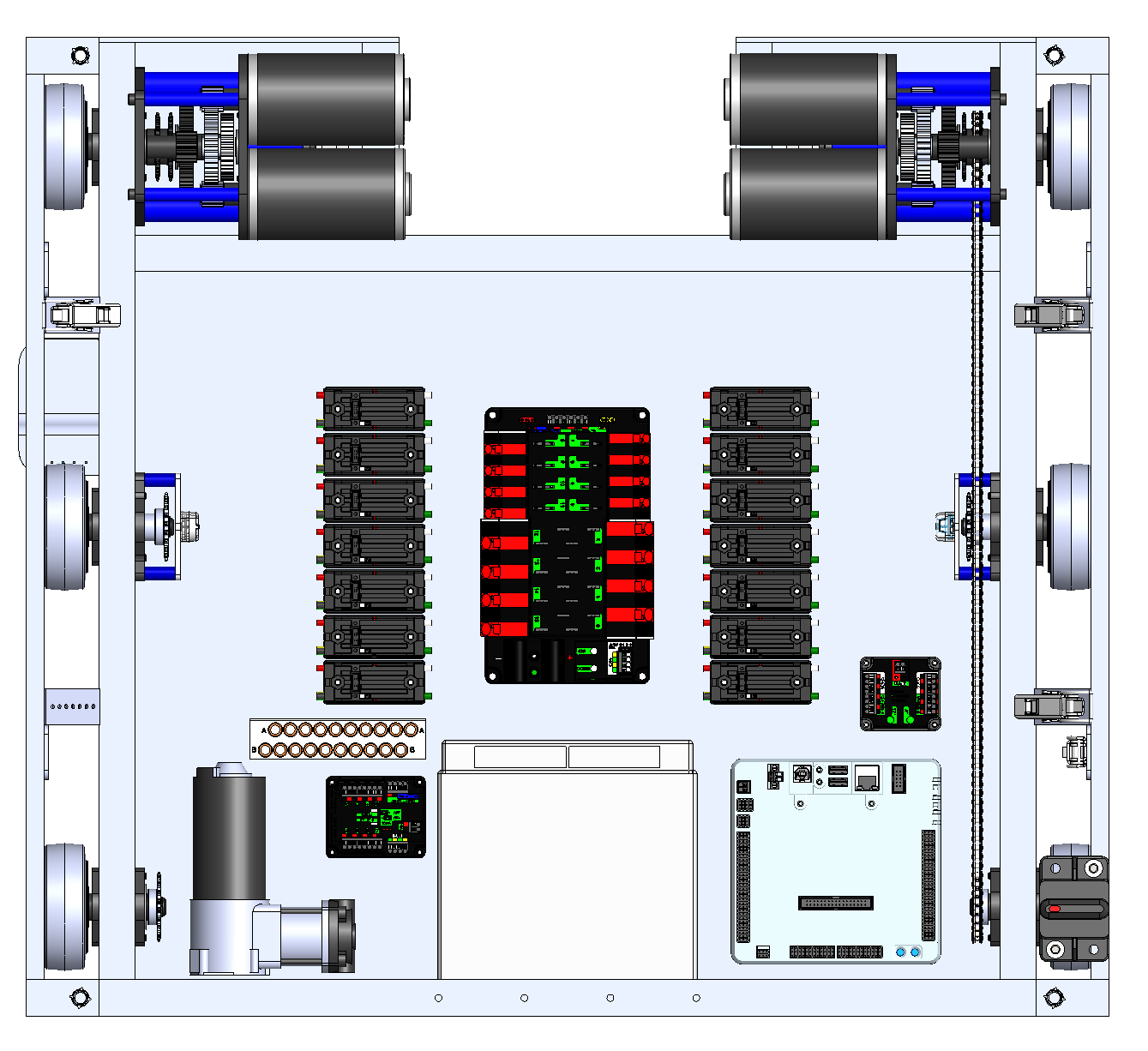
Drivebase
Today we nailed down an initial version of our drivebase which included the weldment, electronics baseplate, gearbox, and wheels. To finalize our design, changes may have to be made to the frame dimensions to accommodate both the ball and gear intake as well as the bumpers. Moving forward, our priorities are to pocket the baseplate and waterjet it out of 1/8" aluminum to save weight, design new mounting provisions/supports for the bumper rails for easy access, and potentially modify the main breaker placement which is currently positioned in the bumper rail.
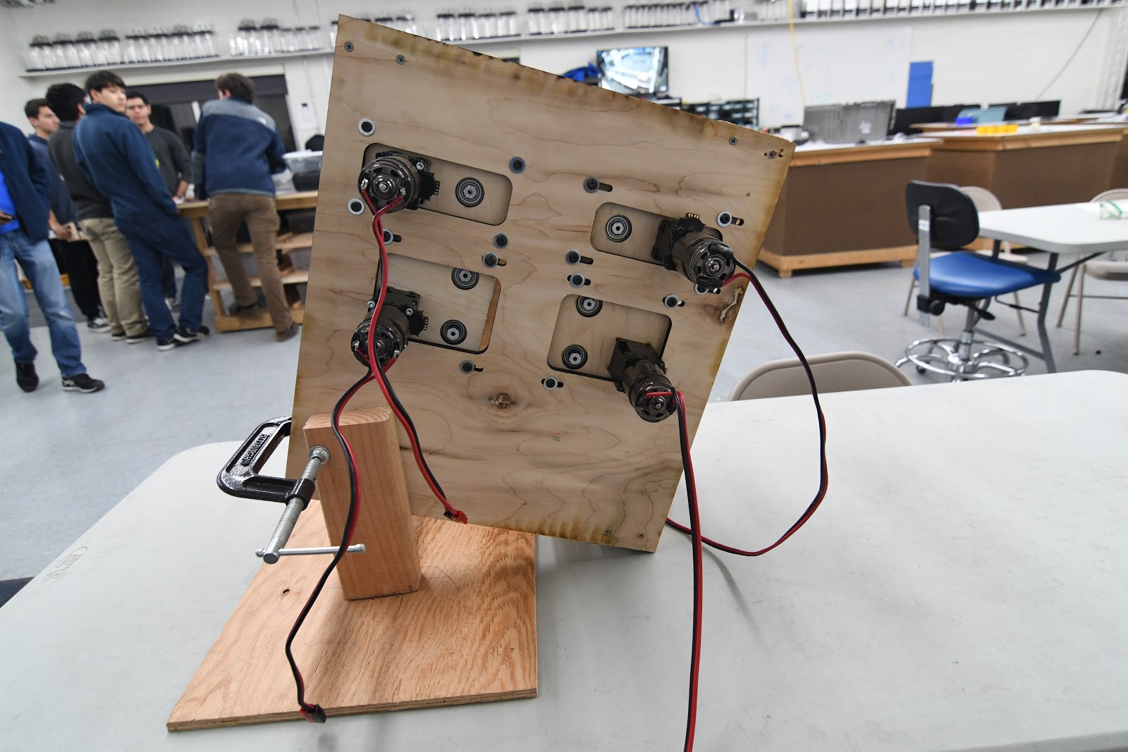
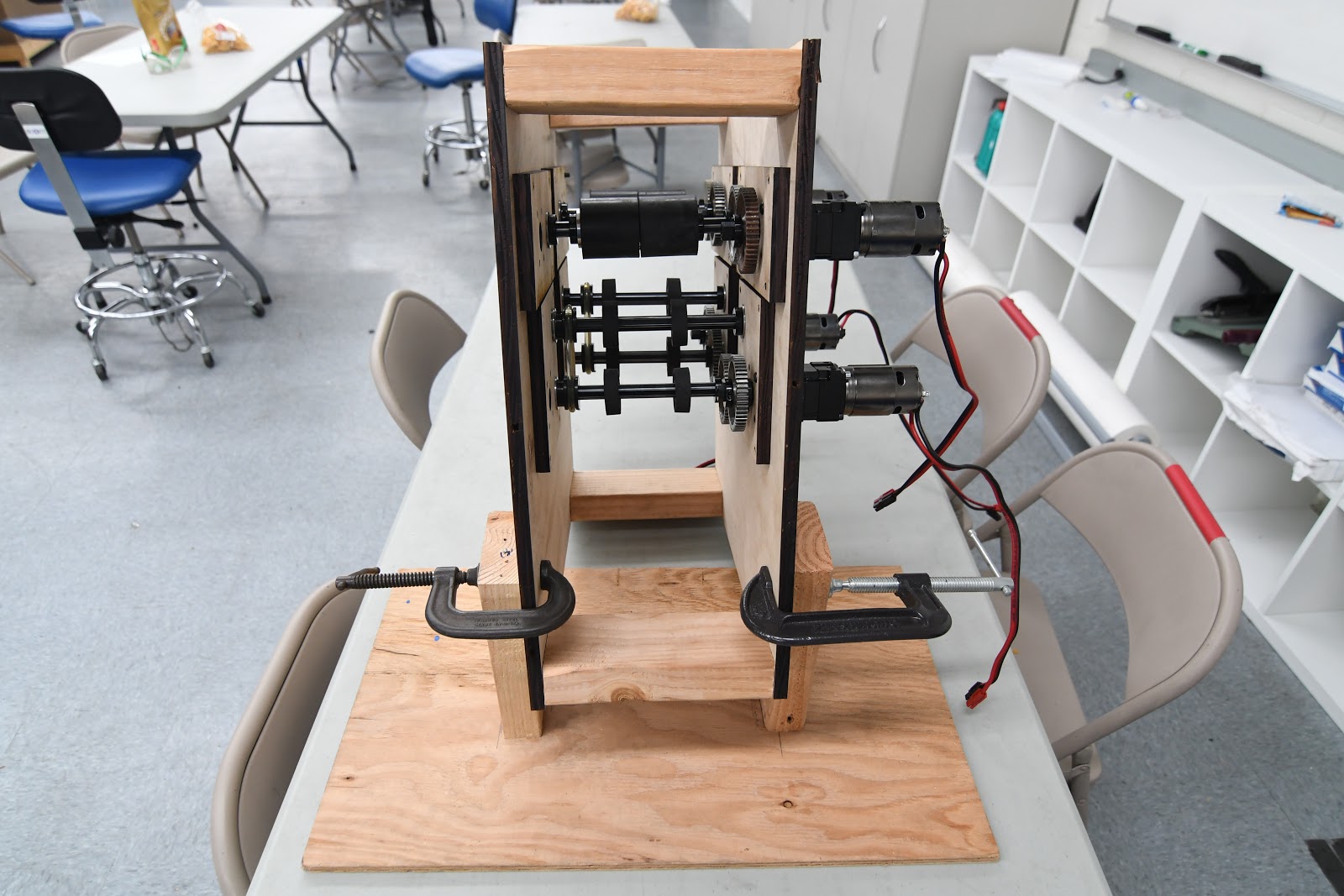
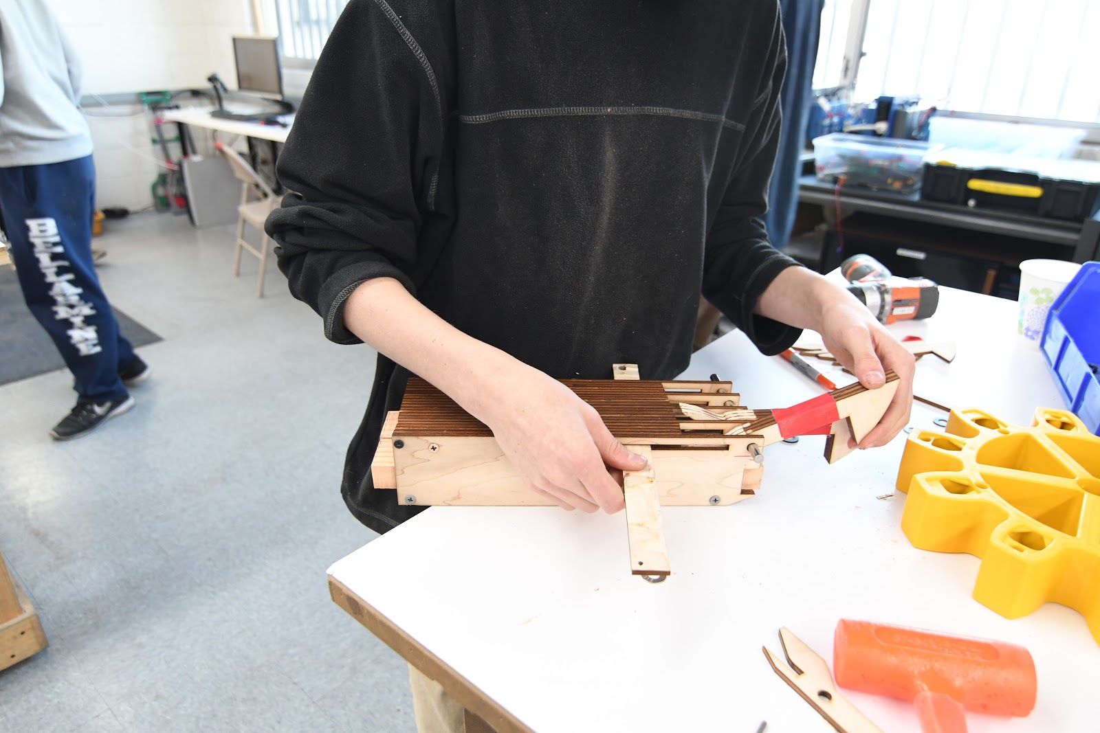
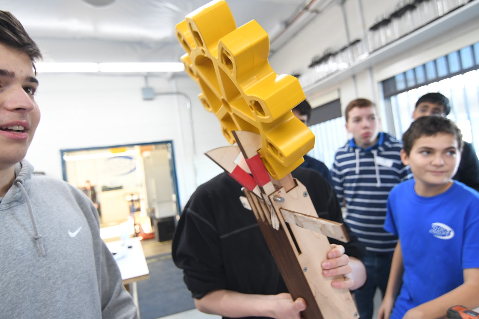
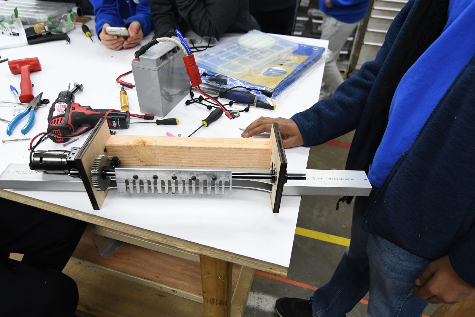
Climber
After mounting the “comb” onto a shaft, we were ready to begin putting together the climbing prototype. However, we soon ran into some problems with the VersaPlanetary gearbox we constructed. After taking it apart and putting it back together (with a 10:1 gear ratio), we were ready to restart testing. At this point we ran into another problem as our setup proved to be unstable, making it impossible for the prototype to run smoothly.. We lasercut new, larger sidepanels and attached them to a 2×4 for stability. Next, we recut the metal bar we had used to stop it from interfering from the turning of the comb. Finally, we were ready to attach it to Dropshot’s drivebase, set up a hanging station, and start testing. While the prototype could successfully grab and hold onto the rope, it just did not have enough power to life the entire robot (even after changing to a 50:1 gear ratio in the VersaPlanetary). Looking toward the next build, we’ll have to find a way to increase the prototypes strength and speed.
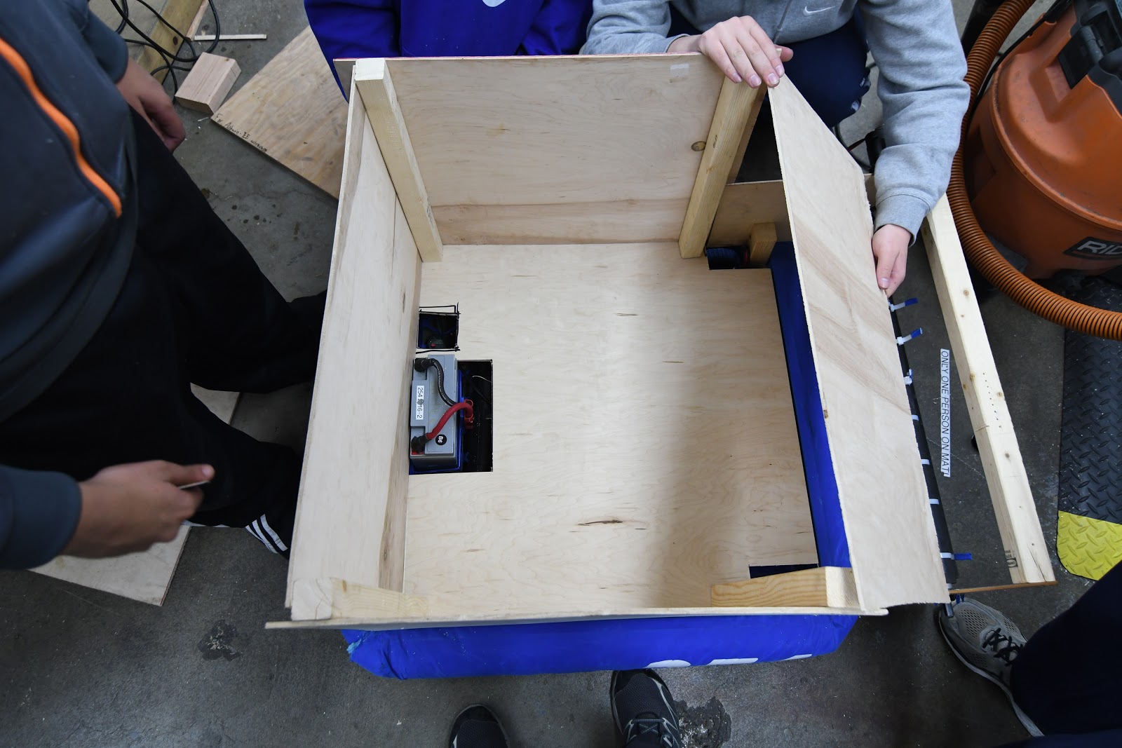
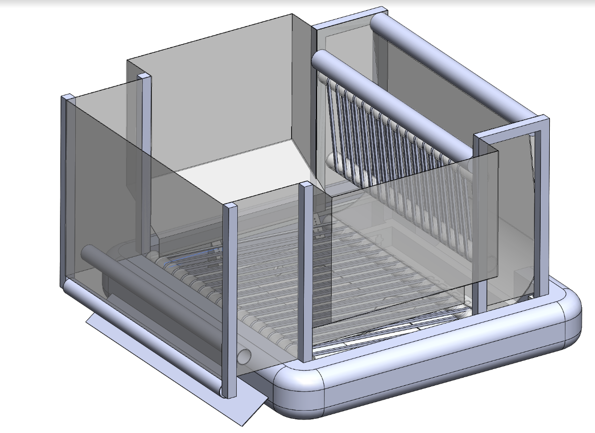
Full Robot Mockup
The team created a quick mock up of the robot that features an intake on the front and shooter in the back. A large hopper made of polycarbonate pops out to over the bumpers to maximize its volume. A system of polycord or belts pulls the balls to the back of the robot then up into the shooter. It not a finalized design but serves as a start to get an idea of how much space subsystems like the bumpers and drivetrain take up so they can start being manufactured.
Programming
Robot Programming
Today, we fine-tuned a PID control loop for the intake. PID is a control algorithm that maintains a constant RPMs on a motor, regardless of motor loads. For example, a ball launcher’s motors may slow down when balls are inserted due to the increased load. PID would keep the motor’s RPM constant when a load like a ball is inserted.
We also rewired the encoders to connect to the RoboRIO instead of from the CAN Talon. At the moment, we are running our PID + feed forward loops off the RoboRIO (instead of the CAN Talon) and need the encoders to connect to the RoboRIO. While we can get encoder values from the CAN Talon, we need perfect time synchronization for the control loop on the RoboRIO, which we can accomplish by connecting the encoder to the RoboRIO.
Camera Connectivity
Today, we continued on the previous build’s progress, and decided to continue working on SPI. First, we connect the PixyCam to an Arduino and used the Arduino library to see if it worked correctly with the Arduino, as it hadn’t been working with the RoboRIO. Our test was successful, and the PixyCam worked as expected with the Arduino, leading us to conclude that there was a problem in the communication between the PixyCam and the RoboRIO. We connected the RoboRIO and Pixy pins to an oscilloscope to ensure that data was being transmitted correctly. After a few minutes of trying to get proper data, we realized that the PixyCam only broadcasted data when it saw an object; when no objects were detected, it would only send null bytes. This was the reason for the issues yesterday; when we got null bytes, we thought there was a communication error with the Pixy, as the documentation did not indicate that no data would be transferred when no objects were detected; we expected frame separators, but none were sent. After realizing this, we put a ball in front of the camera, which had been programmed to recognize balls, and updated our RoboRIO program to search for objects in a loop. At last, we were able to successfully retrieve object metadata, but we encountered connectivity issues between our driver station and the RoboRIO and were not able to finish our code. This build, we were able to get our program to parse the Pixy’s object broadcast data. Next build, we plan to finish our SPI driver by parsing the frame separator indicators, so we can recognize when there are multiple recognized objects in a single frame.
