
FRC Day 9 Build Blog
Day 9: Flywheel and Prototypes
Prototyping
Topspin Single Wheel Flywheel
The topspin shooter continued testing today with several small changes made throughout the build. We remade yesterday's prototype and varied the hood length to see how it affected accuracy. We started the day by testing the 4" flywheel with top spin. We took the working design, and redesigned the prototype to not be adaptable, and in doing so we also designed an integrated feeder. This design worked relatively well. We iterated on the optimal amount of wrap on the ball, starting with around 120 degrees, and going as far as 80 degrees, without testing further. As we iterated and continued testing, we realized the difficulty of packaging a topspin flywheel, so unless we are able to show that topspin is more consistent, it is unlikely that we will use it in the final design. We also tested a backspin 4" flywheel by simply rotating the shooter. The design worked, but needed further optimization. We set upon further iterating on this by CADing an entirely new design.
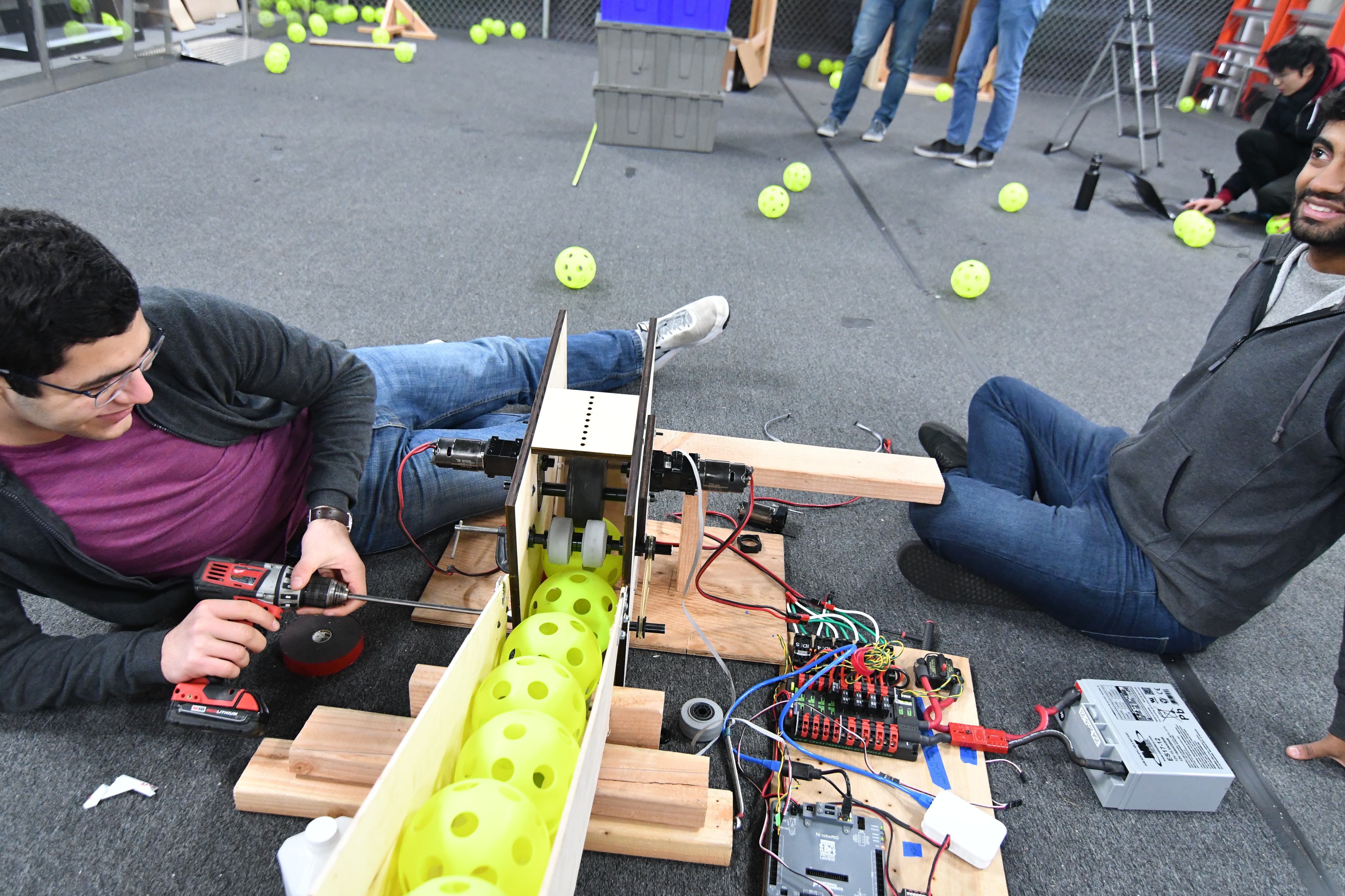
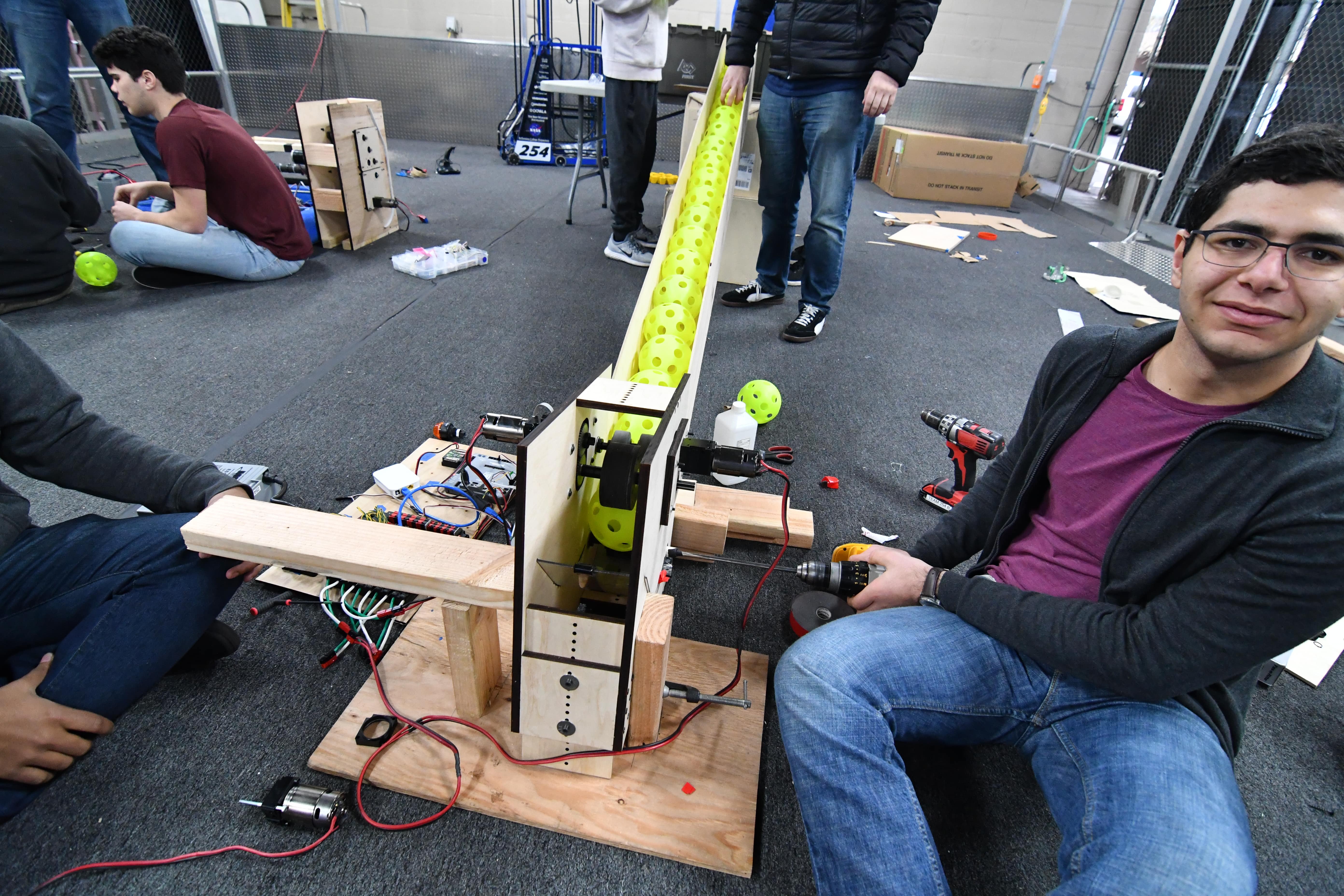
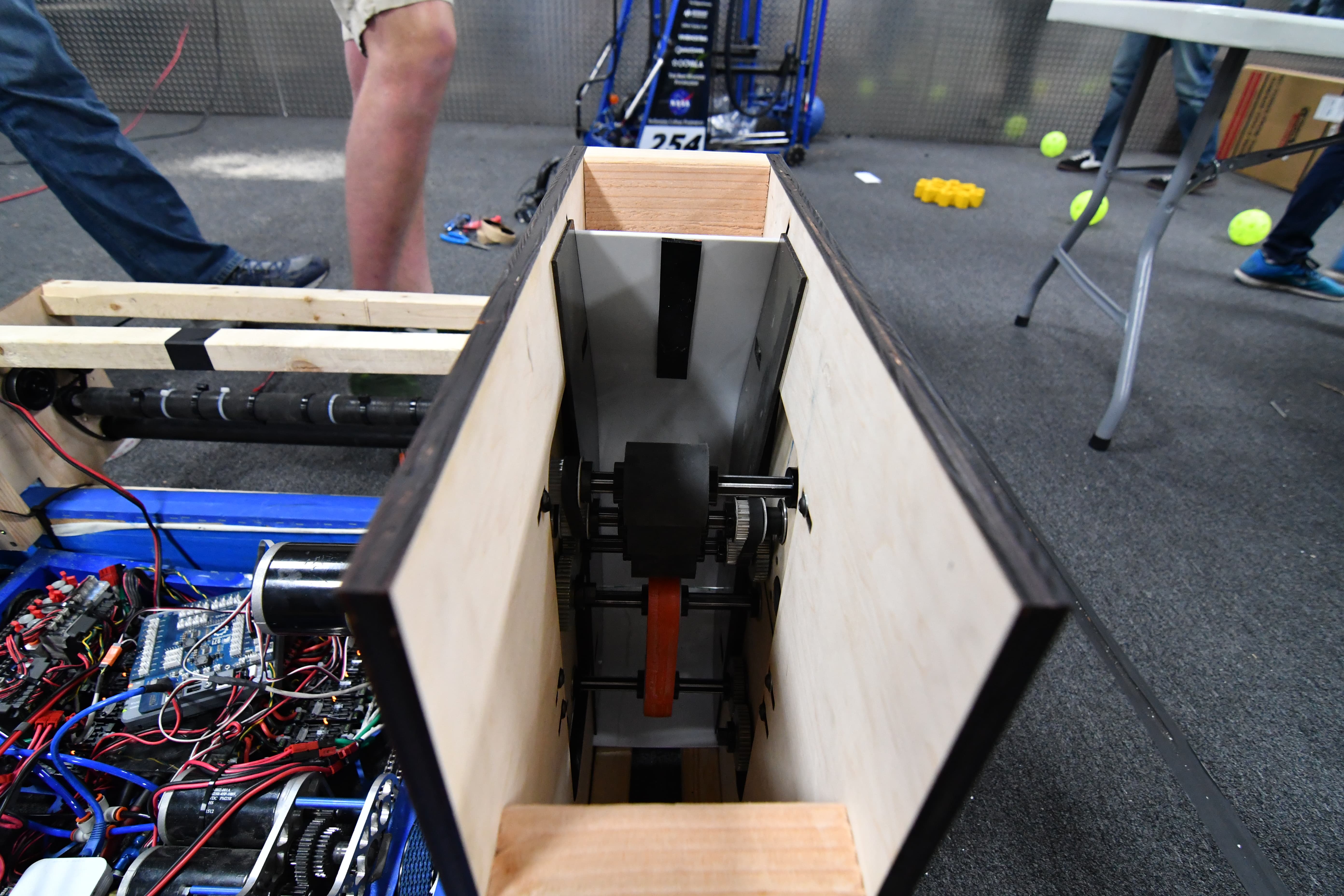
Backspin Single Wheel Flywheel
Today, we remade the single 2" Fairlane Flywheel prototype, but this time we fixed all the little bugs from before as well as added two more 2" wheels in the exit. This concept was to see if it would make the shot more accurate, but it didn't pan out. We reverted to the single wheel design, which worked beautifully. This backspin shooter was really consistent and accurate for the first successful iteration and it also makes packaging the shooter into our robot much easier. We also worked on designing a three-parallel-shooter prototype that would have three of these shooters side by side for maximum shooting rate..
Drivebase CAD & Design
We continued work on drive frame detailed design. Other team members started exploring space claim models for the entire robot, including the hopper, shooter, gear mechanism and drive train. We also looked at possible packaging for the topspin shooter that was working well. We decided that for simplicity, the ball feeder chute on the rear of the robot should not deploy over the bumper, and that it is better for it to stay rigid for consistent ball feeding. We still plan to deploy the hopper on the front, and possibly sides, of the robot.
-min.jpg)
-min.png)
Field Construction
We cut plastics and installed the top of boiler so that more accurate shooter testing could proceed.
Manufacturing
We will be continuing our work on making drive gearboxes. We finished de-tabbing gearbox plates and started making gearbox standoffs. Several students continued on mill/lathe training with test parts.
Programming
We restructured the robot code to offload control of the drivetrain from the Drive subsystem file to the main Robot Java file. The Drive system’s code runs every 1 ms, while the robot’s code runs every 5 ms. The driver station sends and drive data every 5 ms, so moving the code saves considerable processing power. This also allows for other functions to be implemented in the Drive subsystem.
Following our all-hands meeting yesterday, we finished the autonomous routine visualizer, which allows us to design and visualize an autonomous routine using a series of points. We also finished a parser that turns the visualizer output into usable robot code. We also implemented an adaptive pure pursuit controller, which helps the robot correct any deviations and return to its pre-planned route. This requires an odometer to track the robot’s distance travelled and heading, which we also implemented. We are currently establishing the groundwork for the robot’s autonomous routine, which we will implement when we have a final robot.
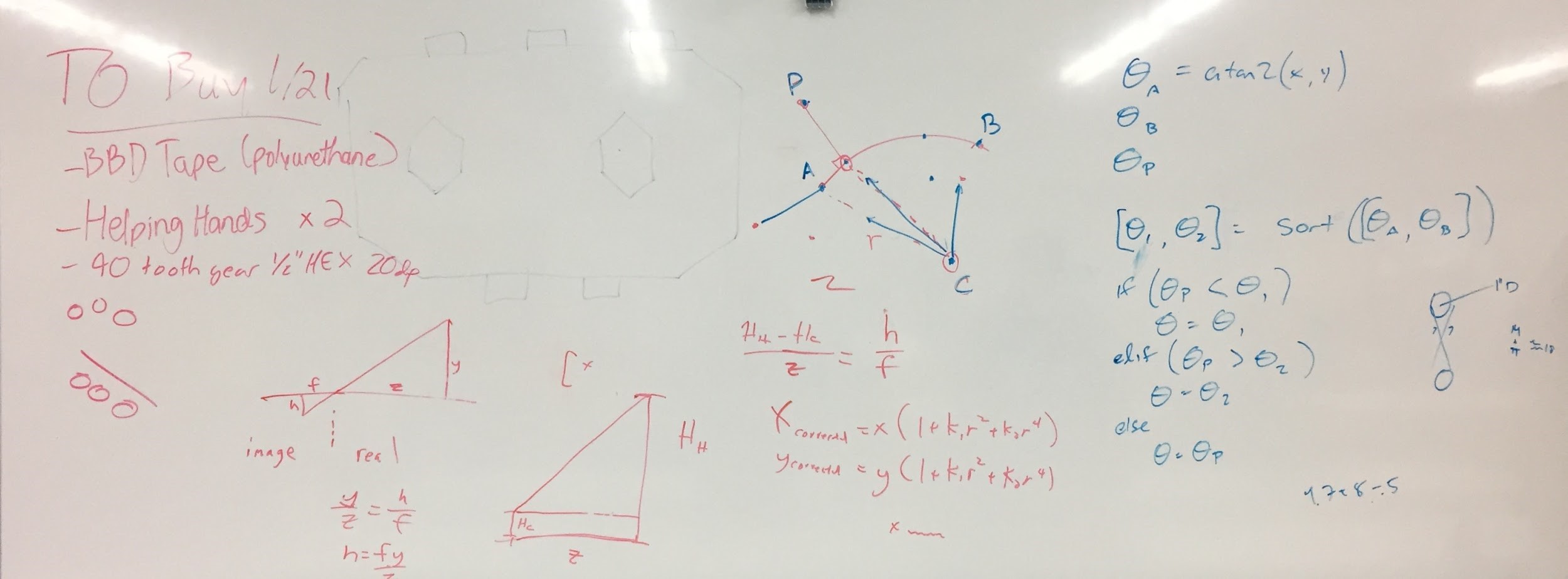
Camera calibration
Today we finished camera calibration code. It works really well, and now outputs the distortion numbers to a .txt file for easy access. Now, we are working on incorporating that into the SPI code so the Roborio has access to the undistorted image data. We need to figure out how to undistort the image while keeping it in a RAW format.
In addition to receiving calibration results, we discussed how to then take these calibration constants and apply them to remap the raw image coordinates to adjusted ones that map to physical locations on the field. We consulted a handy opencv guide.
Here's the picture of our whiteboard discussion:
Programming On The Prototypes
A lot of progress was made today with prototyping. We wrote new code to add a closed PID control loop to the feeder of the new overhand/backspin prototype and we returned constants to work with the new flywheel. In doing this, we discovered numerous bugs in the constant setting code and we have remedied many of them. Most of the time was spent supporting the prototyping effort with various control tweaks to maximize performance.
