
Day 18: Prototyping, Testing, and Programming
by Chris Powers and Jack Lee
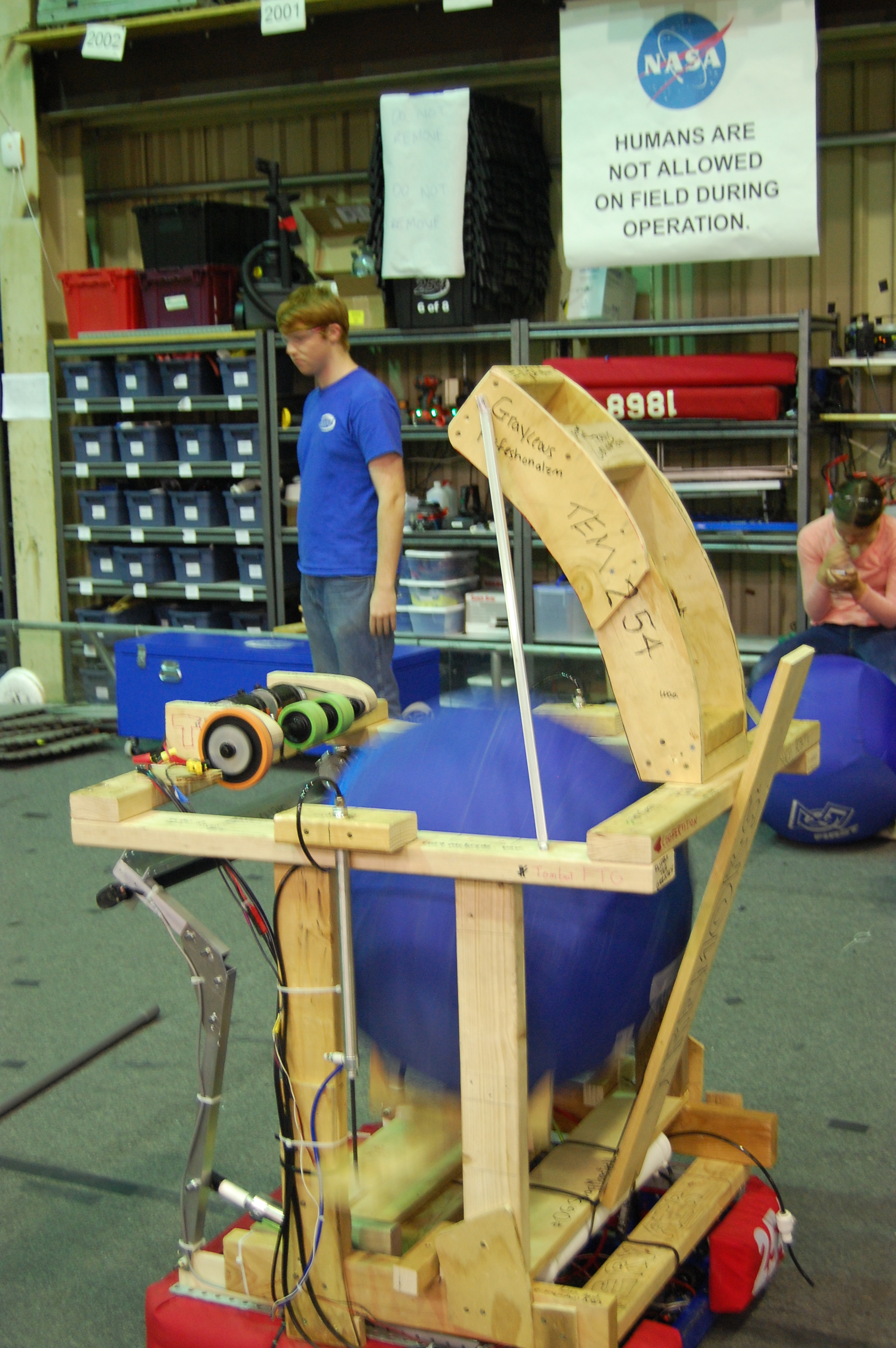
Prototyping
Today, work continued on testing the prototype robot’s lift mechanism, which uses pneumatic pistons to lift the ball from the intake of the robot to the flywheel shooter. This lift worked successfully during most of the tests. The hopper prototype uses a V-shaped mechanism to lift the ball.
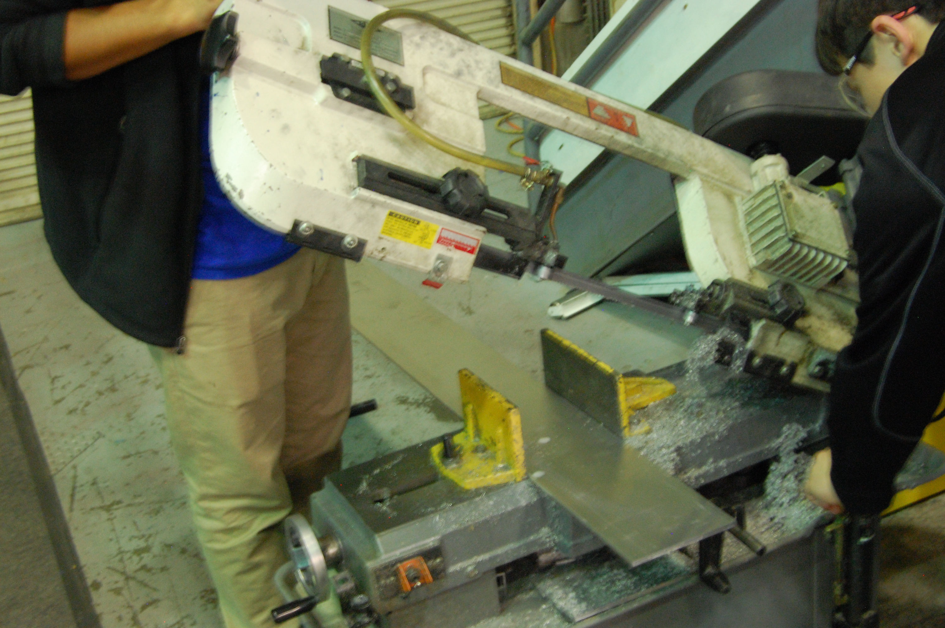
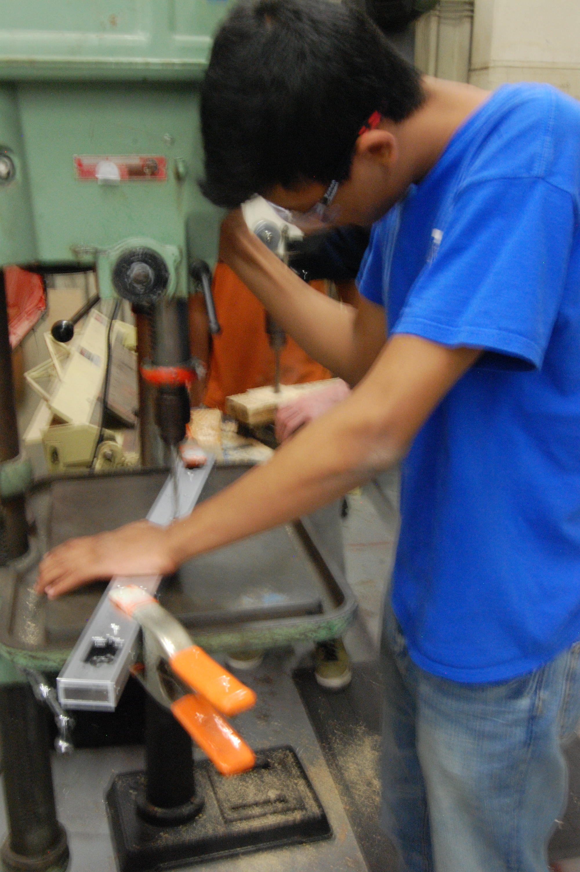
Machining
A group of students created side plates for the gearbox. After the plates were cut and deburred, they were machined on the CNC mill. All pieces for the drive base have been manufactured except for side plates.
Work began on constructing a truss for the field. Also, the wooden goal was disassembled and the official goal will soon be set up.
Programming
The programmers worked to fine tune the shooter mechanism. They created a graph of the model voltage for the shooter and compared it to the actual data with equations. This will allow compensation for the variable factors that affect the input voltage, and will increase shot accuracy.
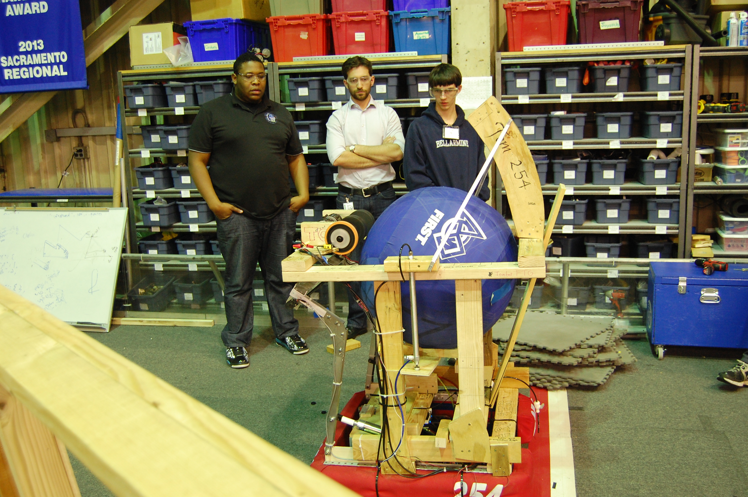
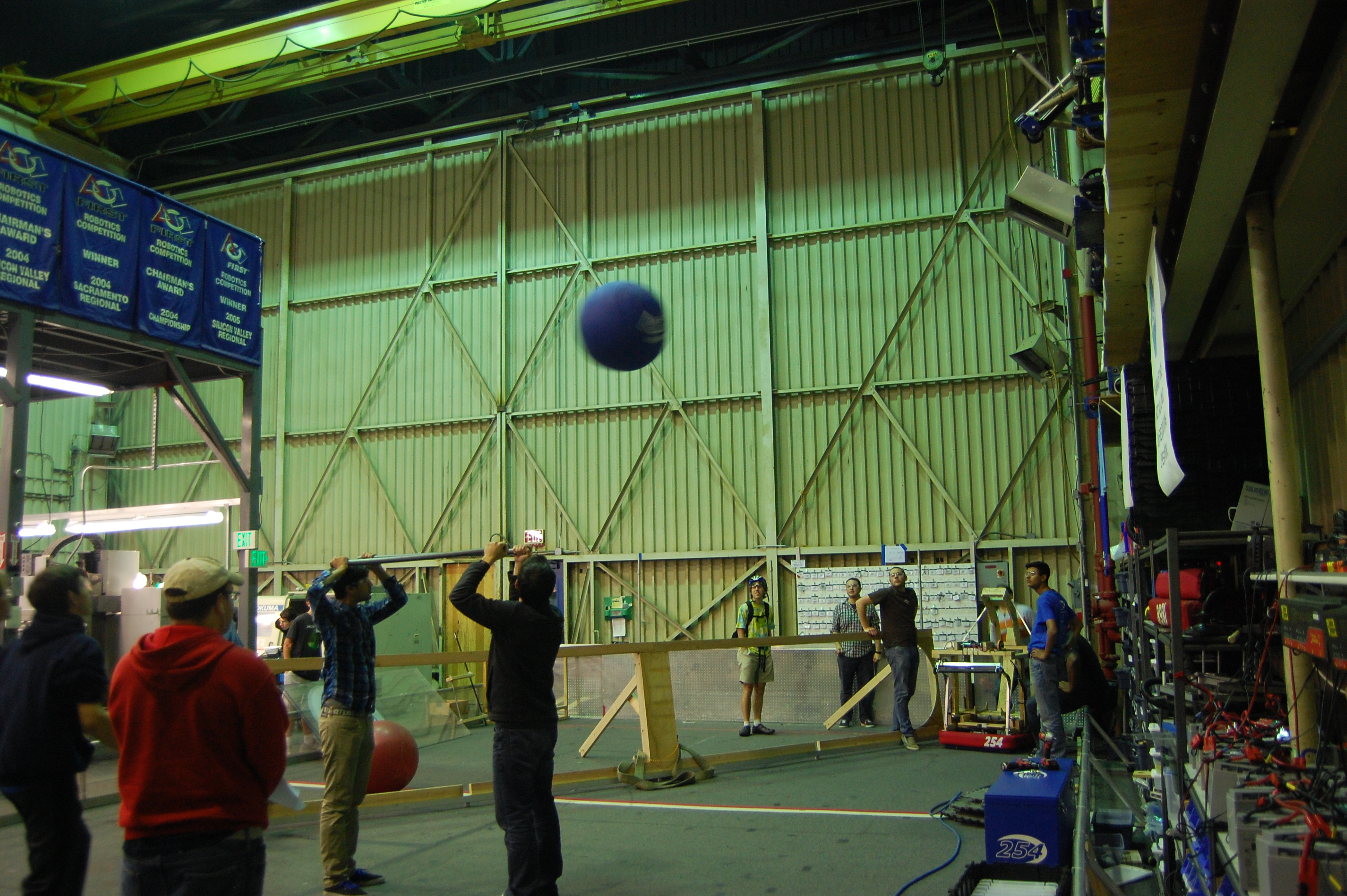
Testing
Many students contributed to testing and refining the shooter mechanism. Many different variables were adjusted to determine the best conditions for accurate and powerful shooting. The shooter speed was varied between 4000 and 5000 rpm and the wheels for the shooter were replaced with slightly larger ones to increase flywheel energy. A banner sensor was added to measure flywheel rotational speed using retroreflective tape. The new flywheels shoot 12 vertical feet, high enough to clear the truss.
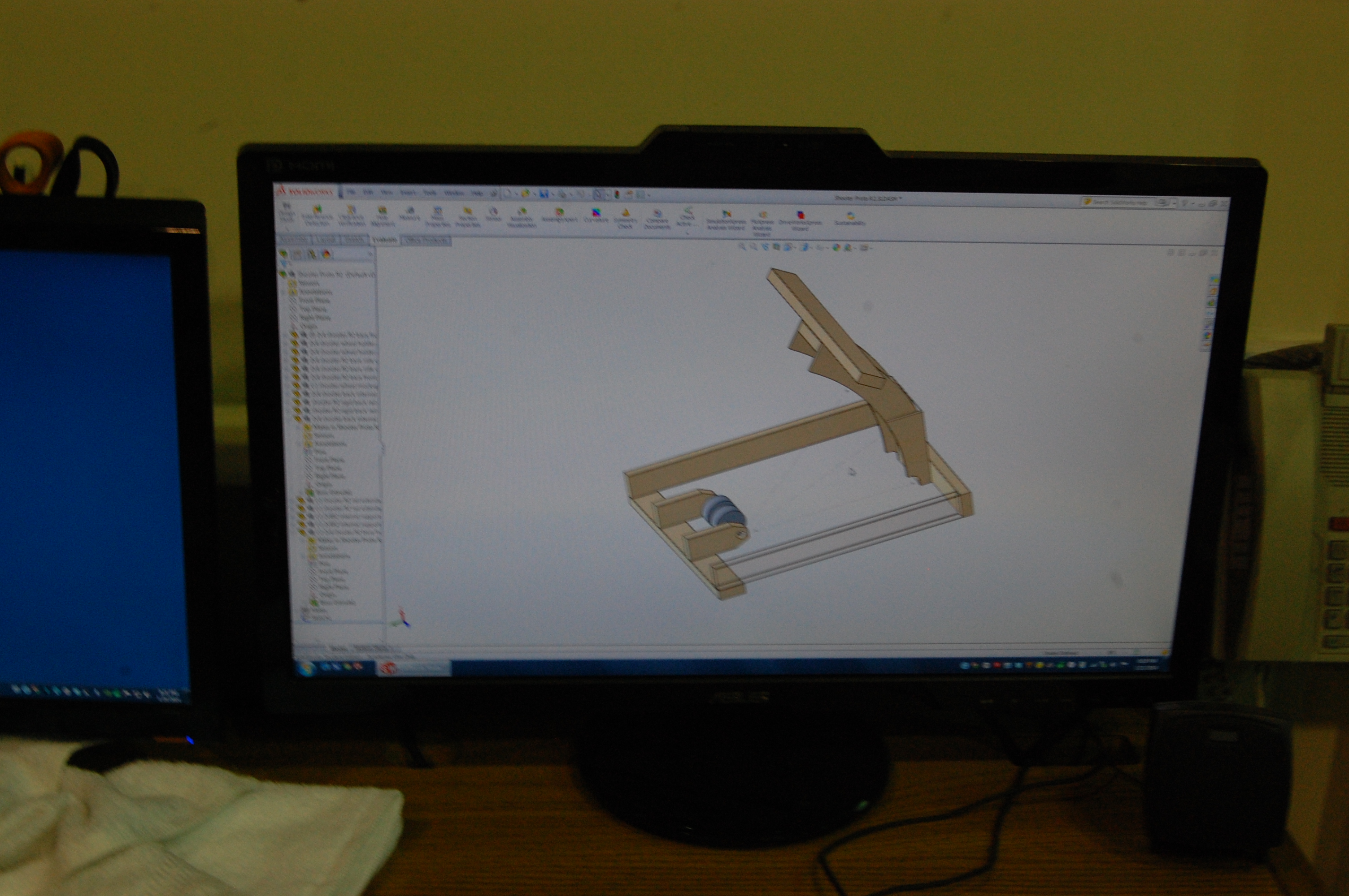
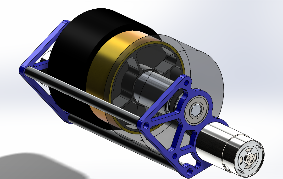
CAD
We began work on the design of a new prototype shooter. This shooter will have a sturdier hood and a lighter wheel. The hood will also have a hood extension that can be attached to replicate the two-position hood on the actual robot.
To design the shooter, students learned about moment of inertia and used SolidWorks to roughly estimate the mass and moment of inertia of the current extra weights on the shooter prototype. We used those numbers to estimate the mass and moment of inertia that we can add to the flywheel in place of the metal gears currently in place on the shooter. These numbers allowed us to model a copper tube with less mass and a similar moment of inertia which will be pressed around an aluminum hub and installed on the robot. More information on moment of inertia is available online.
Action Items
- Check the Trello
- Assemble the weldment
- Start on catcher prototype with Colin
- Test the new shooter wheel and new prototypes thoroughly with Abhi: build adjustable hood for testing shooting angles: test for shot distance for hood angles and ball pressure
- Complete CAD of bumpers, superstructure, and battery cart with Andrew and Mani
- Possibly build new flywheel weight.
