
Day 7: Prototyping, CAD, Testing, & Lab Improvements
Catcher & Intake Prototype
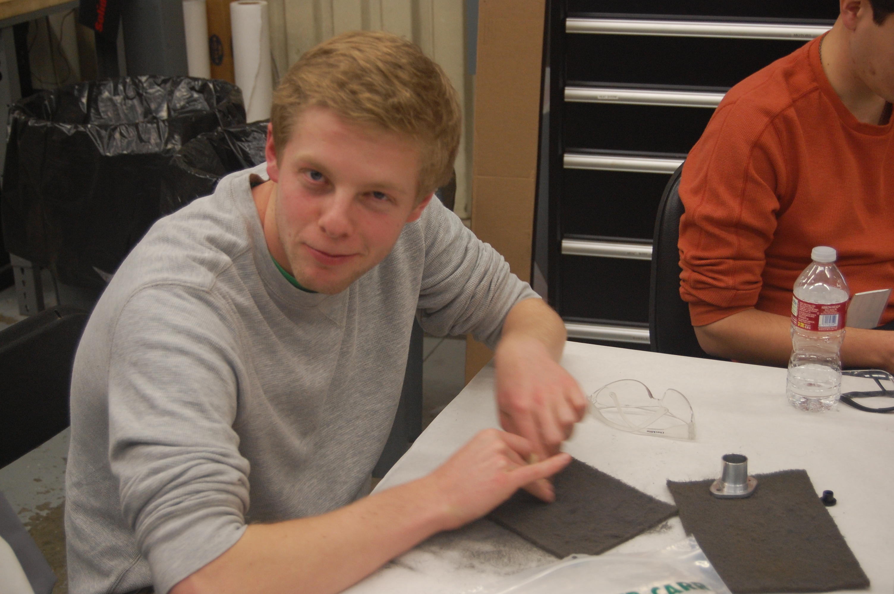
Today, several team members integrated the intake and catcher prototypes with the 2013 practice robot drive base to create a prototype robot that can catch and intake the balls. They removed the catcher arms from the back and front of the drive base and placed the intake in the back of the drive base. Additional planks of wood were attached to the walls of the intake to increase the compression on the ball while from the intake.
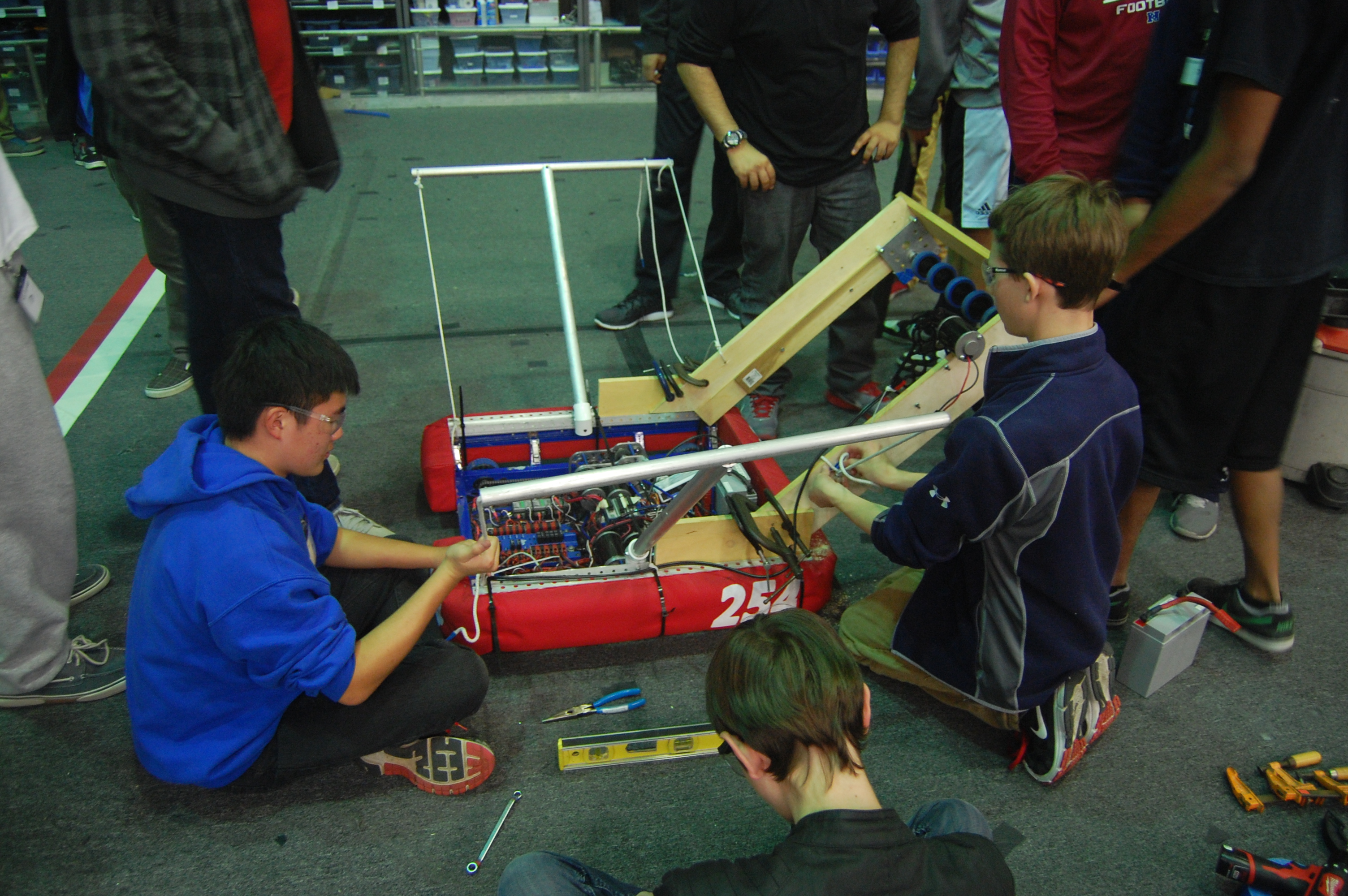
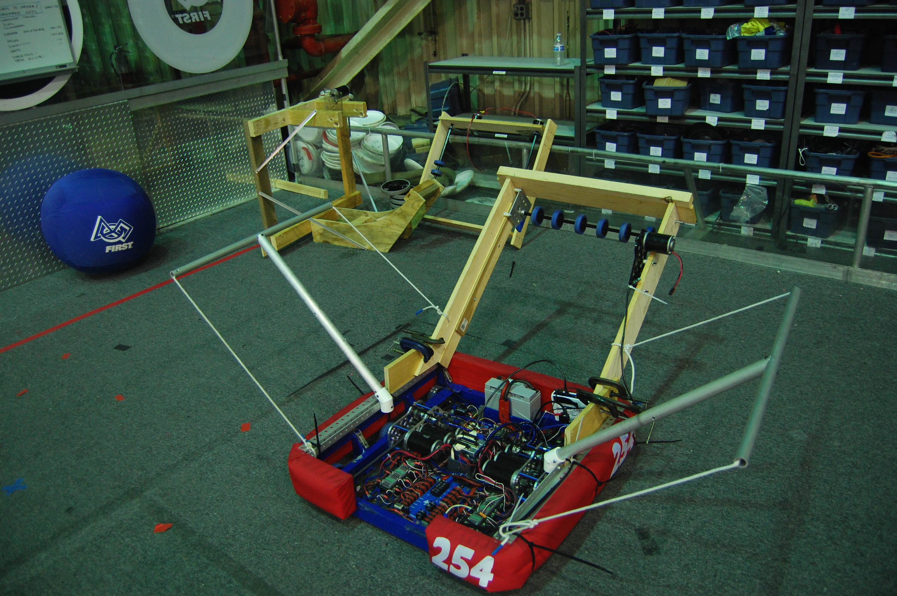
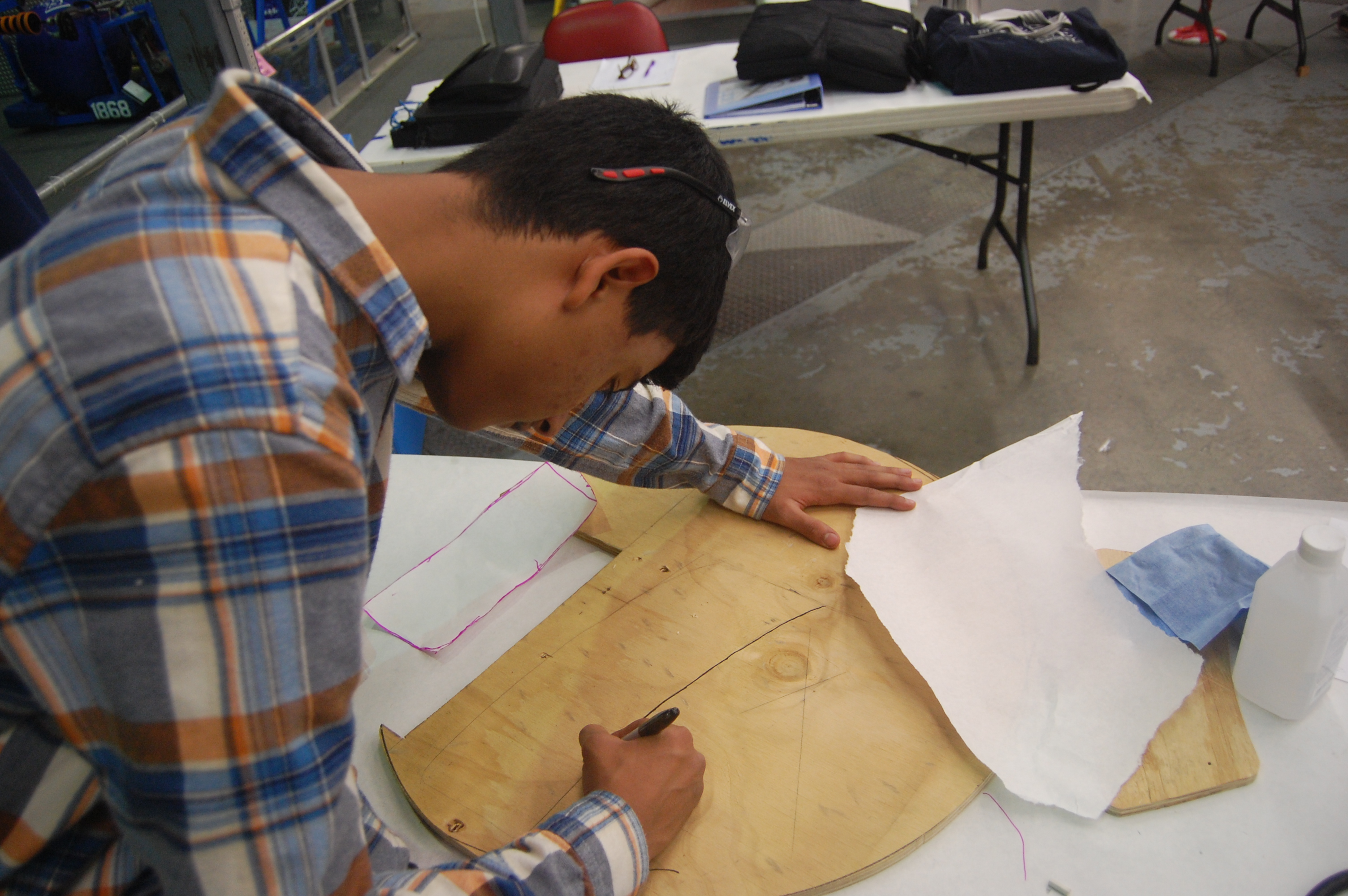
Several students began working on a new intake roller prototype. This new mechanism uses 1.5″ neoprene rubber rollers instead of the current 3.5″ blue bane’s bots wheels that are currently being used.
Shooter Prototype
A group of team members worked on further tuning the shooter prototype. They also performed several tests using different shooting angles and different distances from the goal in order to determine the optimum shooting distance.
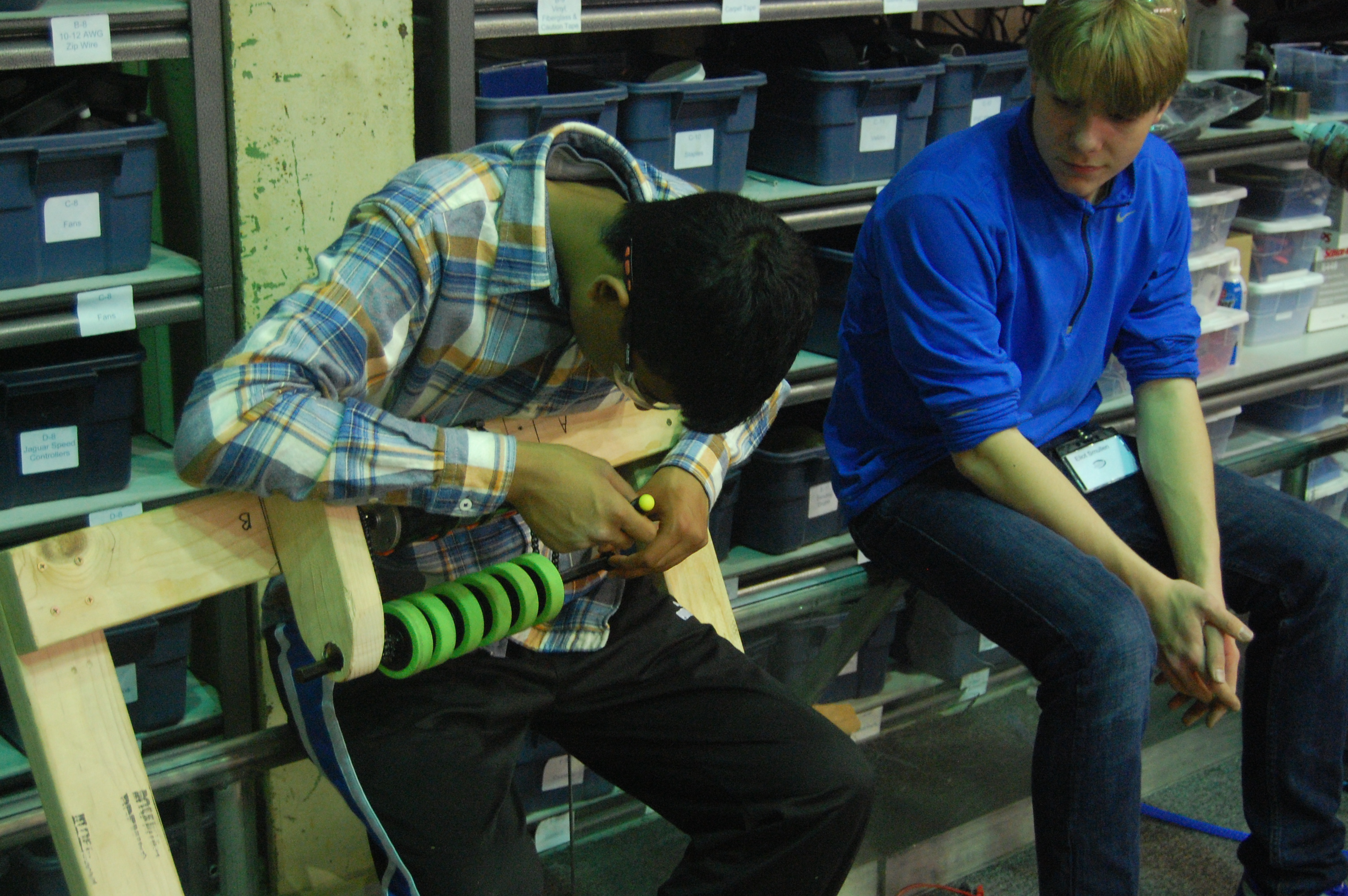
Additionally, we began to improve the shooter prototype by adding reinforcements to the base and machining a new hood.

Prototype Testing
The groups working on the shooter and the integrated catcher and intake prototype came together to test whether or not it is possible for us to shoot over the truss using the current design. The conclusion is that the design will work, but it needs further tuning to be consistent. This test was done by using a “dummy truss,” also known as EJ.
The same group also tested whether or not it is possible for another robot to catch the ball as it is being thrown over the truss. The special constraint that we tested was whether or not the catching robot could start at the same position as the throwing robot and be able to drive fast enough to catch the ball. Although this robot has the same ratios as we are planning on using for the 2014 robot, it lacks a superstructure and is lighter, resulting in superior acceleration.
CAD
Work continued on the design of the drivebase for the robot. Right now the drive base is functionally identical to the previous year’s drive base. The only major changes have been the mounting points for the superstructure, which have been moved closer to the bumper mount to allow for a superstructure wide enough to hold the large balls in this game.
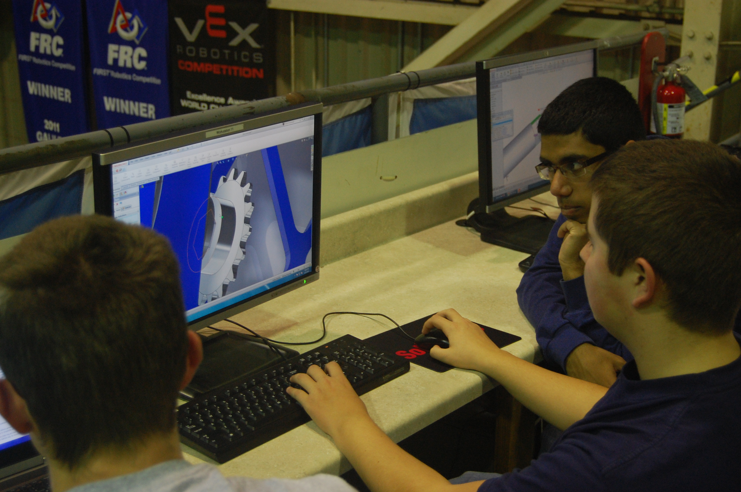
The team also got together to design the look of the rest of the robot. They discussed how to integrate the two intakes, the shooter, and the catcher into the robot and the overall design of superstructure. Right now there is a rough idea of how the robot should look. Further detailing will be based on the results of prototyping.
Lab Improvements
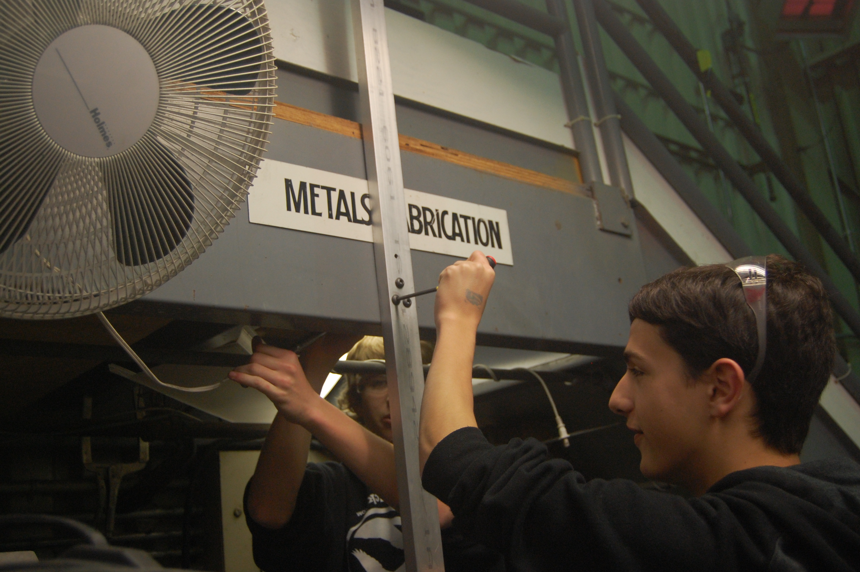
Today, we also worked on installing better light fixtures over the metals fabrication area in the lab. This will improve the lighting of the area, which will also improve machine quality and safety.
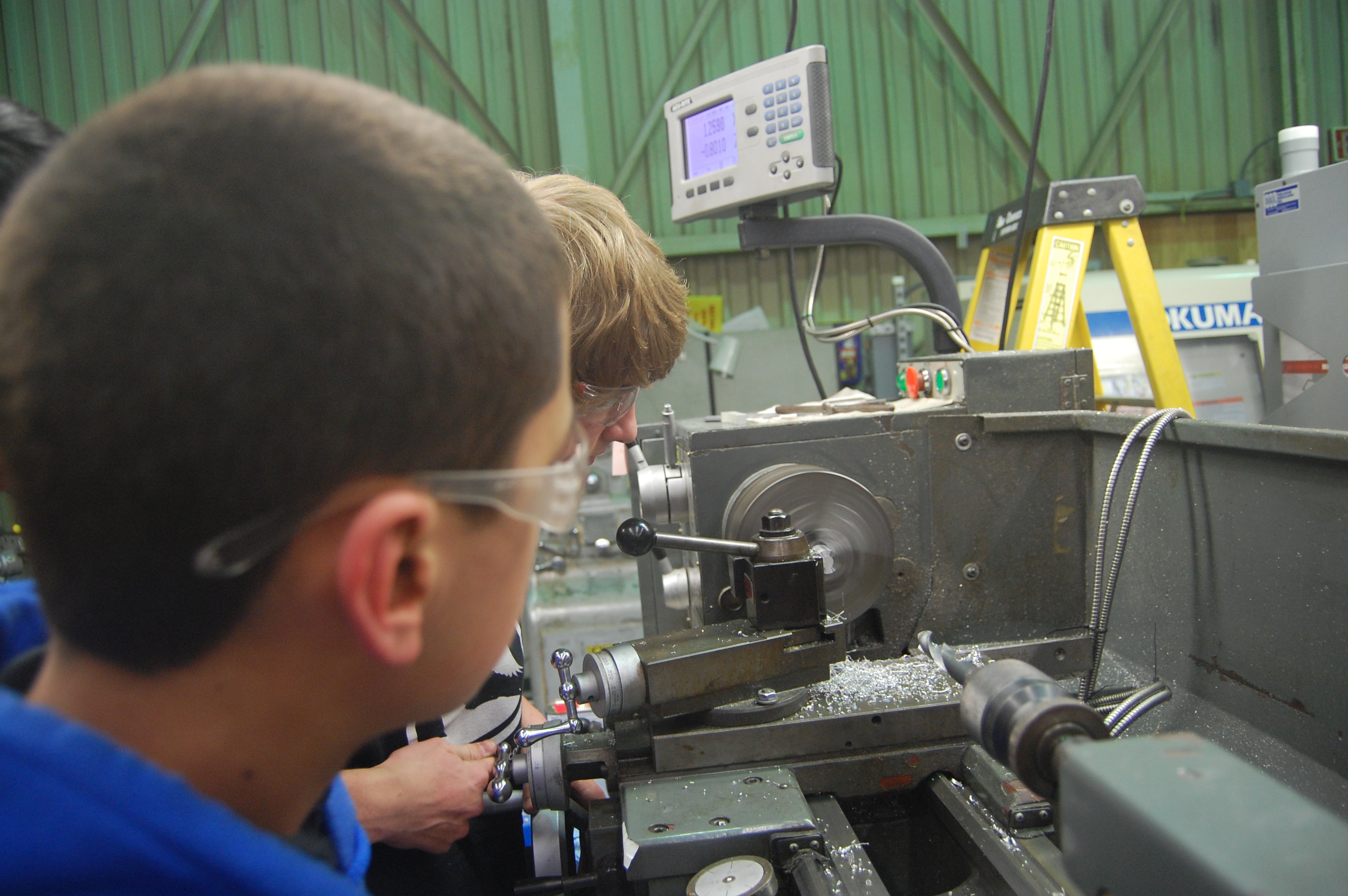
Manufacturing
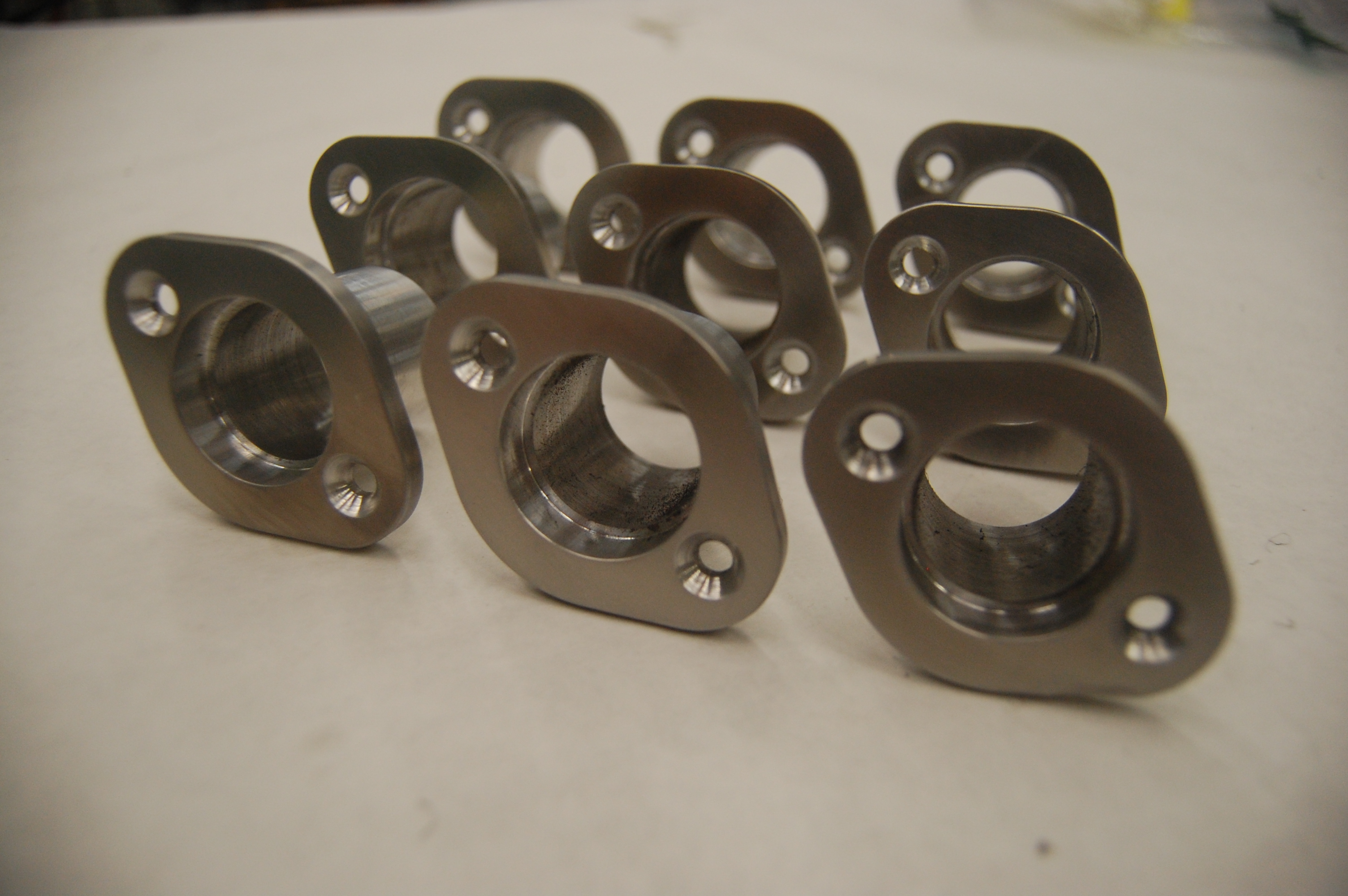
The center bearing housings for the drive base were finished and polished today. As a result the manufacture of additional parts will begin.
Action Items
- Continue testing shooter prototype
- Finish manufacturing new intake prototype
- Finish drive base CAD
- Send baseplate for manufacturing
- Continue designing rest of the robot
- Begin manufacturing parts for the drive base
