
Blog Archive
Day 30: Machining, CAD, Game Elements, and Drive Base
By Clay Rosenthal
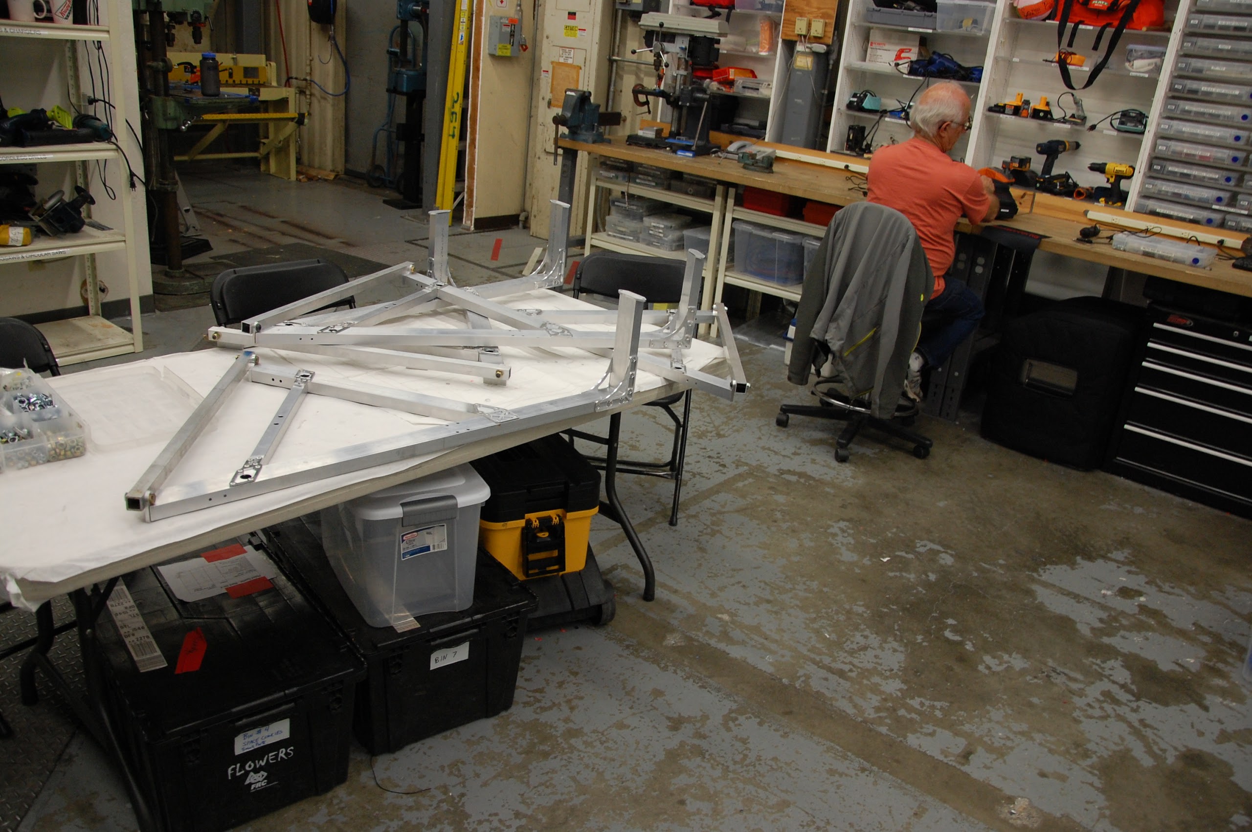
Machining
Parts of the superstructure were made today to be welded tomorrow. Parts to hold the pieces in place while being welded were also machined. The superstructure will be welded and powder\-coated soon. The parts for the hood and rear intake were also assembled and will soon be welded and prepped for powdercoating.
CAD
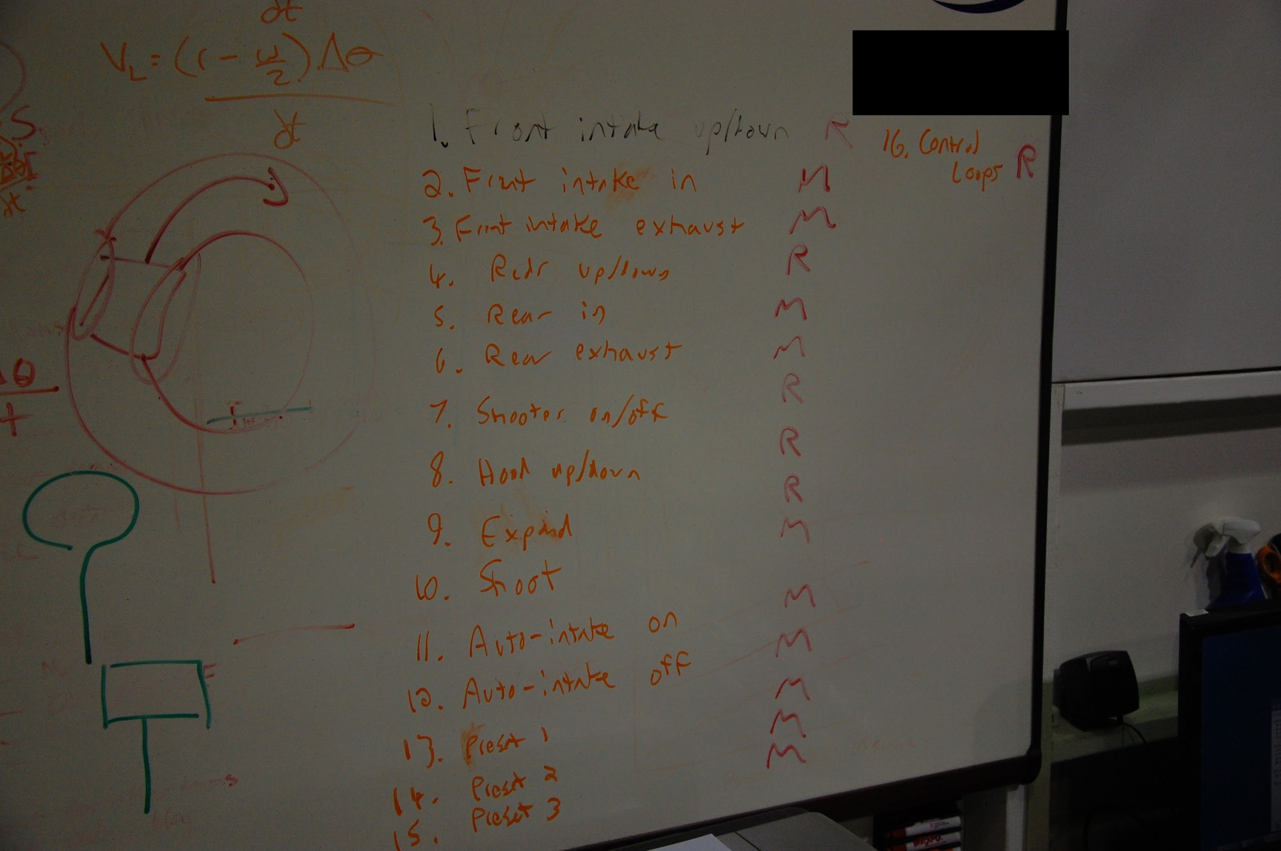
The clapper design was worked on today and is nearing completion. Locking pistons for the hood were also conceptually designed on today. A new control board with sixteen buttons is being designed. The buttons are described below \(‘R’ stands for rotational, or a switch, and ‘M’ is for momentary, or a button\).
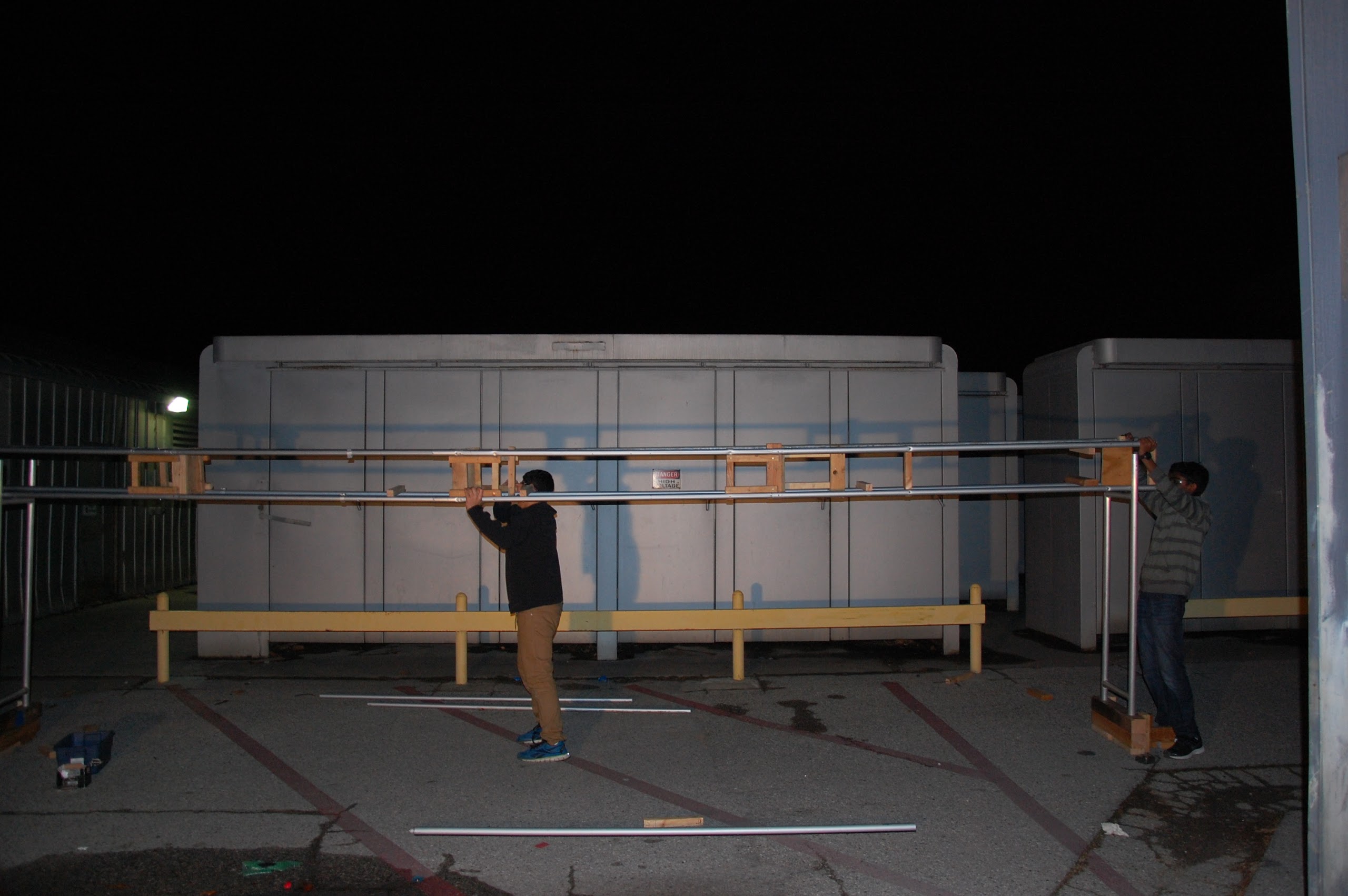
Game Elements
The truss was worked on more today and is nearing completion. It is standing tall but still bending. The two halves from yesterday were attached together. It hasn’t been hung over the field yet and is still being completed outside.
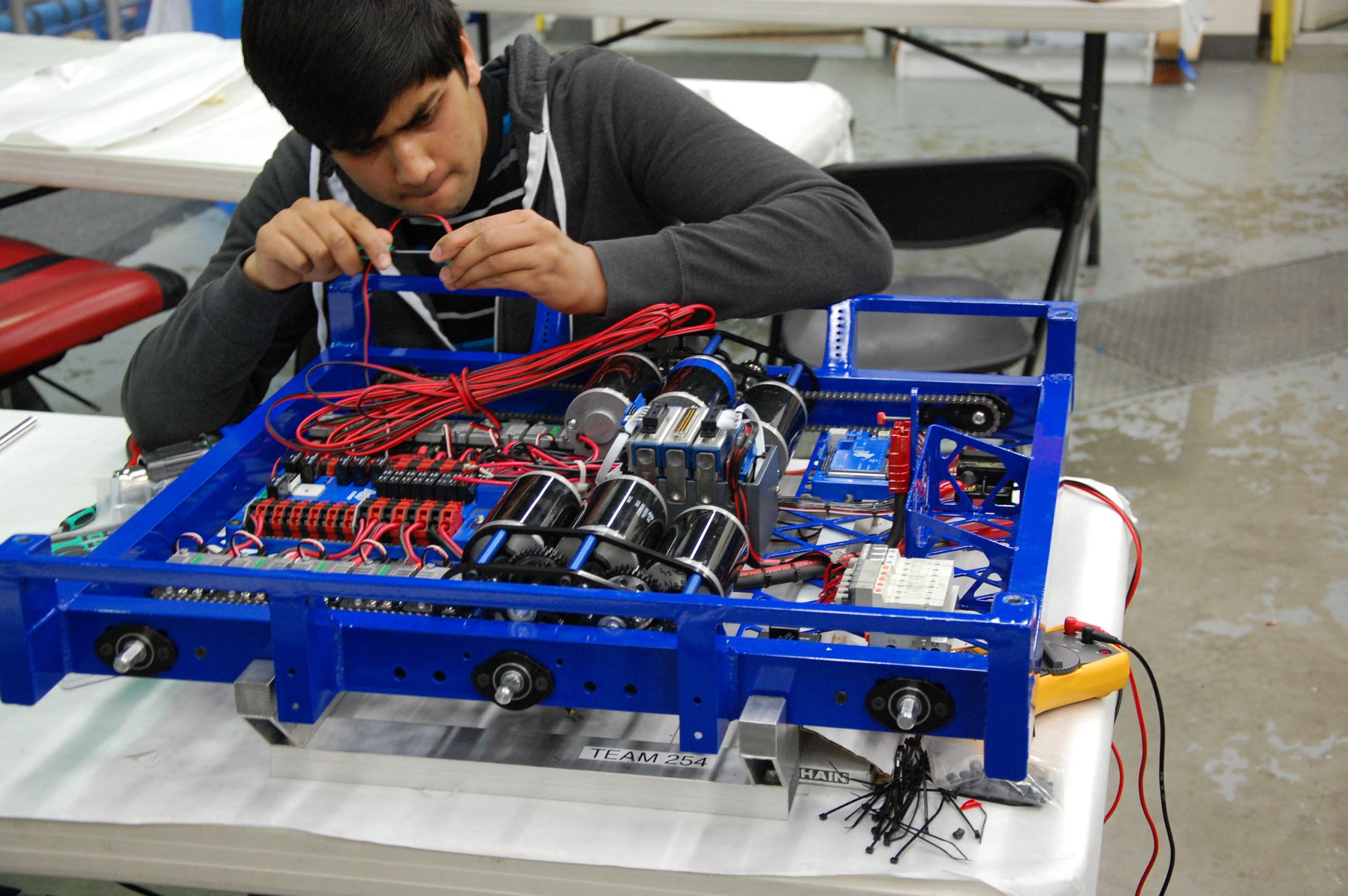
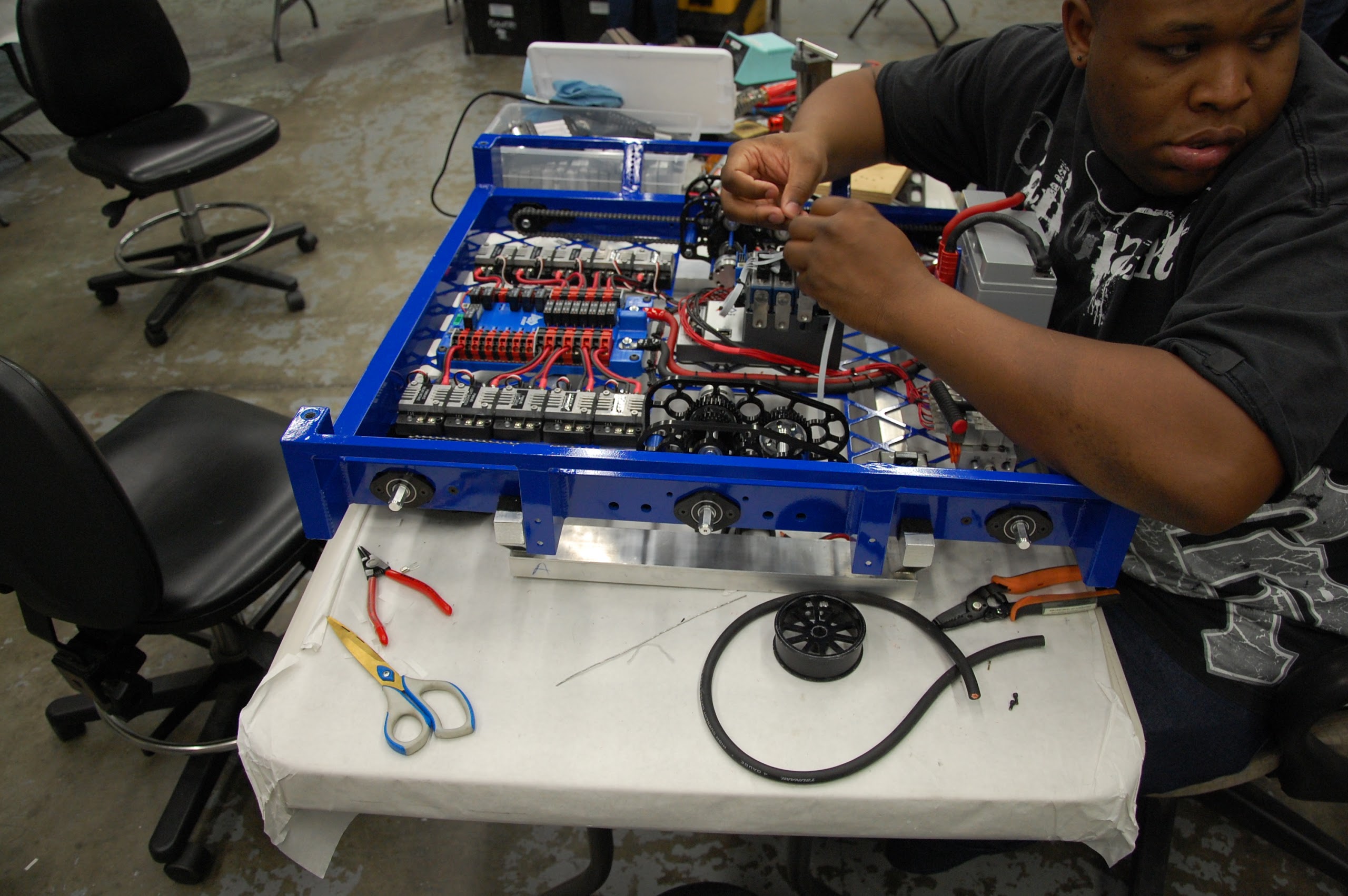
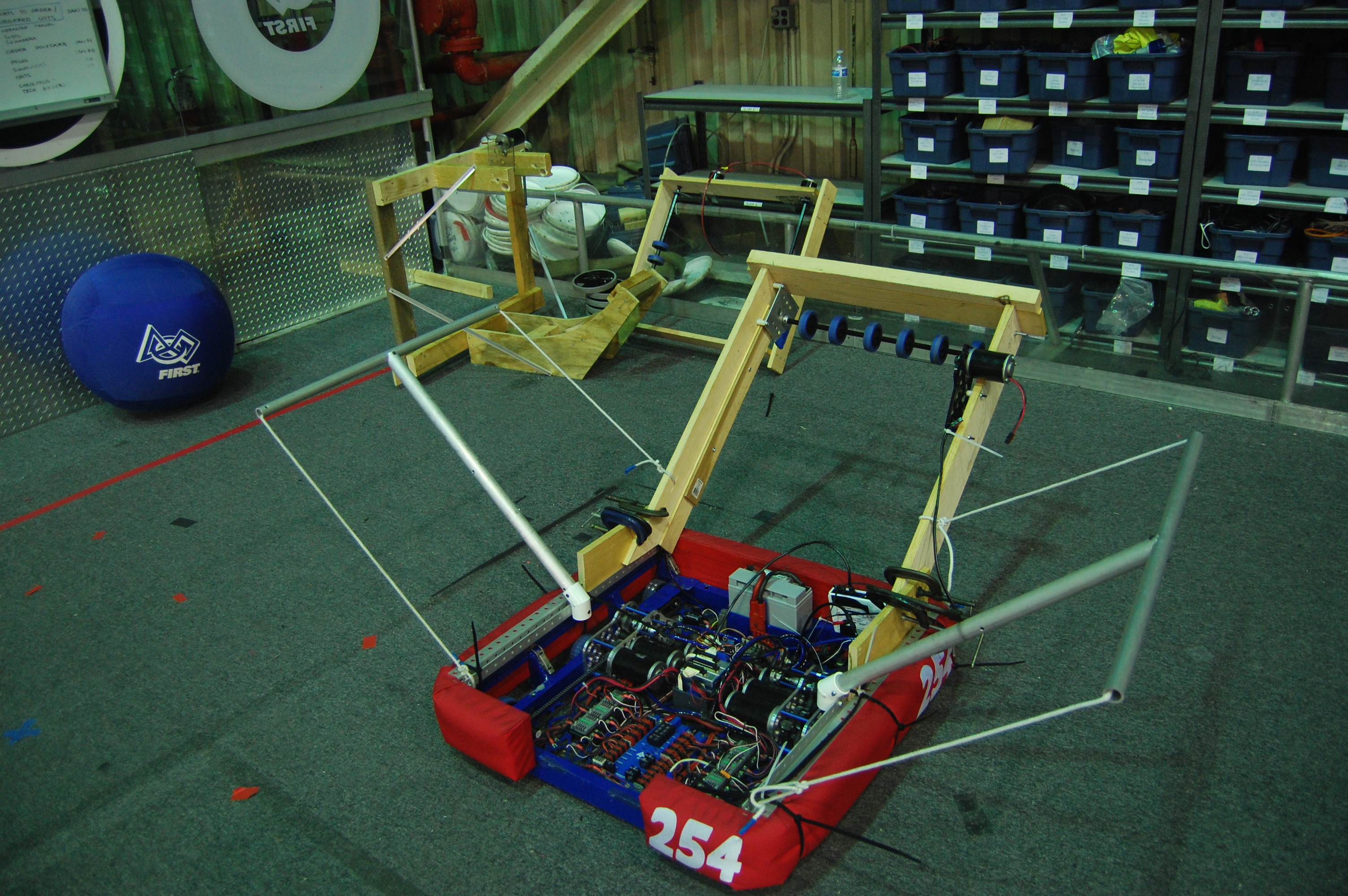
Drive Base
The competition drive base was wired and is pretty much ready for driving. The practice drive base is not far behind. The wheel axles now have chains attaching them to the gearboxes and the gearboxes on the practice drive base have CIM’s on them. New CIM’s have been ordered and will be put on when they arrive.
Action Items
- Wire andersons and drive gearboxes, Ask Mani
- Wire practice robot, Ask Mani
- Get everything ready to be welded
- Machine parts for hood, shooter, and intake gearboxes, ask Pat
- Finalize design for clapper, ask Colin
- Finish parts for shooter, hood
- Machine gearbox plates and piston mountsWire andersons and drive gearboxes. Ask Mani
- Wire practice robot. Ask Mani
- Get everything ready to be welded
- Machine parts for hood, shooter, and intake gearboxes, ask Pat
- Finalize design for clapper, ask Colin
- Finish parts for shooter, hood
- Machine intake gearbox plates and piston mounts
Day 7: Prototyping, CAD, Testing, & Lab Improvements
Catcher & Intake Prototype
Today, several team members integrated the intake and catcher prototypes with the 2013 practice robot drive base to create a prototype robot that can catch and intake the balls. They removed the catcher arms from the back and front of the drive base and placed the intake in the back of the drive base. Additional planks of wood were attached to the walls of the intake to increase the compression on the ball while from the intake.
Several students began working on a new intake roller prototype. This new mechanism uses 1.5″ neoprene rubber rollers instead of the current 3.5″ blue bane’s bots wheels that are currently being used.
Shooter Prototype
A group of team members worked on further tuning the shooter prototype. They also performed several tests using different shooting angles and different distances from the goal in order to determine the optimum shooting distance.
Additionally, we began to improve the shooter prototype by adding reinforcements to the base and machining a new hood.

Prototype Testing
The groups working on the shooter and the integrated catcher and intake prototype came together to test whether or not it is possible for us to shoot over the truss using the current design. The conclusion is that the design will work, but it needs further tuning to be consistent. This test was done by using a “dummy truss,” also known as EJ.
The same group also tested whether or not it is possible for another robot to catch the ball as it is being thrown over the truss. The special constraint that we tested was whether or not the catching robot could start at the same position as the throwing robot and be able to drive fast enough to catch the ball. Although this robot has the same ratios as we are planning on using for the 2014 robot, it lacks a superstructure and is lighter, resulting in superior acceleration.
CAD
Work continued on the design of the drivebase for the robot. Right now the drive base is functionally identical to the previous year’s drive base. The only major changes have been the mounting points for the superstructure, which have been moved closer to the bumper mount to allow for a superstructure wide enough to hold the large balls in this game.
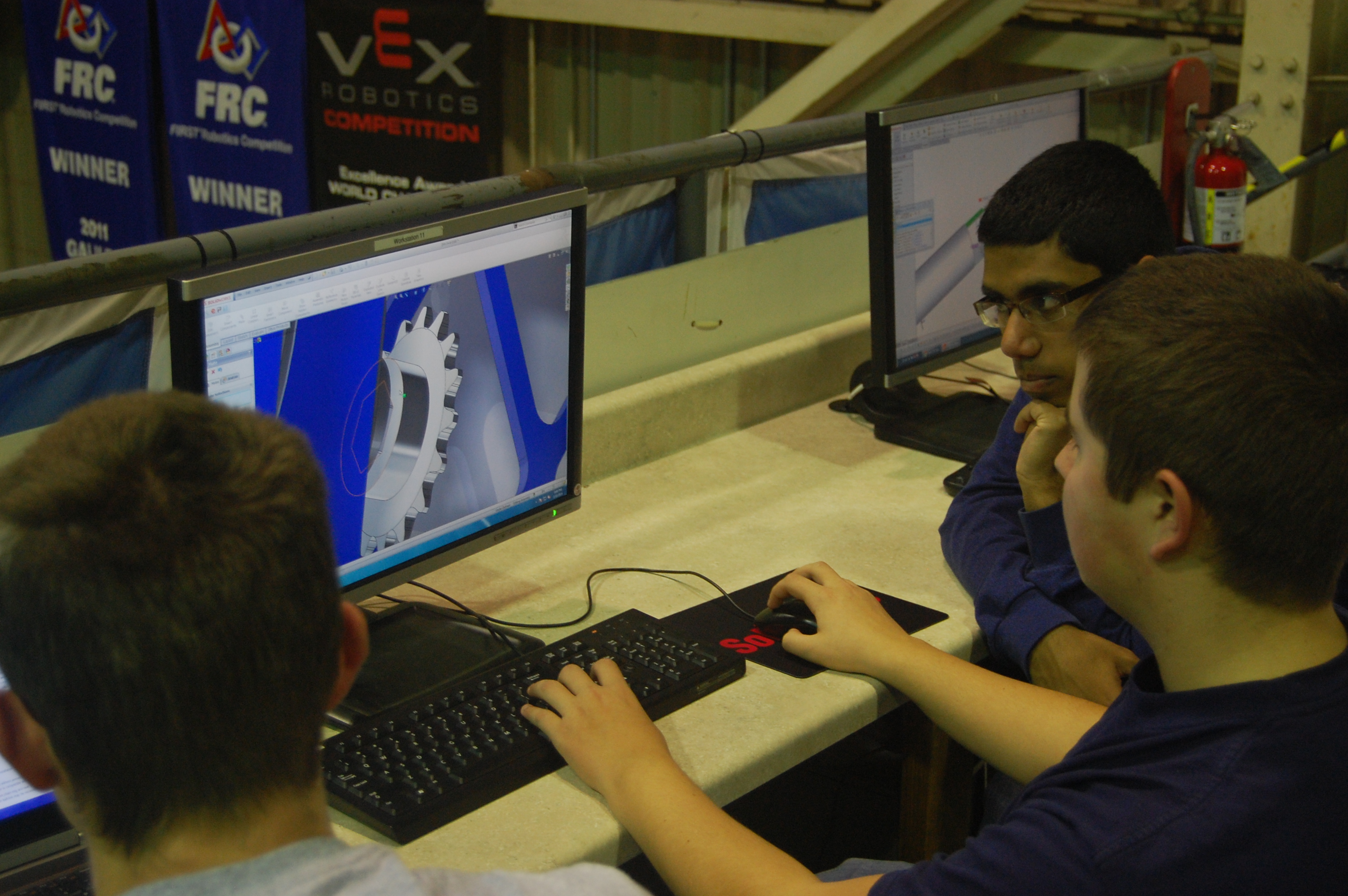
The team also got together to design the look of the rest of the robot. They discussed how to integrate the two intakes, the shooter, and the catcher into the robot and the overall design of superstructure. Right now there is a rough idea of how the robot should look. Further detailing will be based on the results of prototyping.
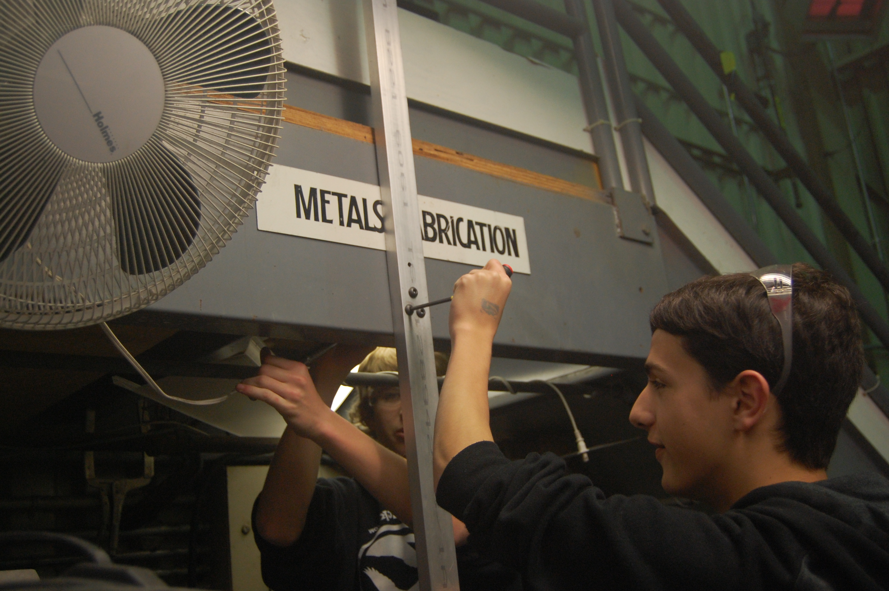
Lab Improvements
Today, we also worked on installing better light fixtures over the metals fabrication area in the lab. This will improve the lighting of the area, which will also improve machine quality and safety.
Manufacturing
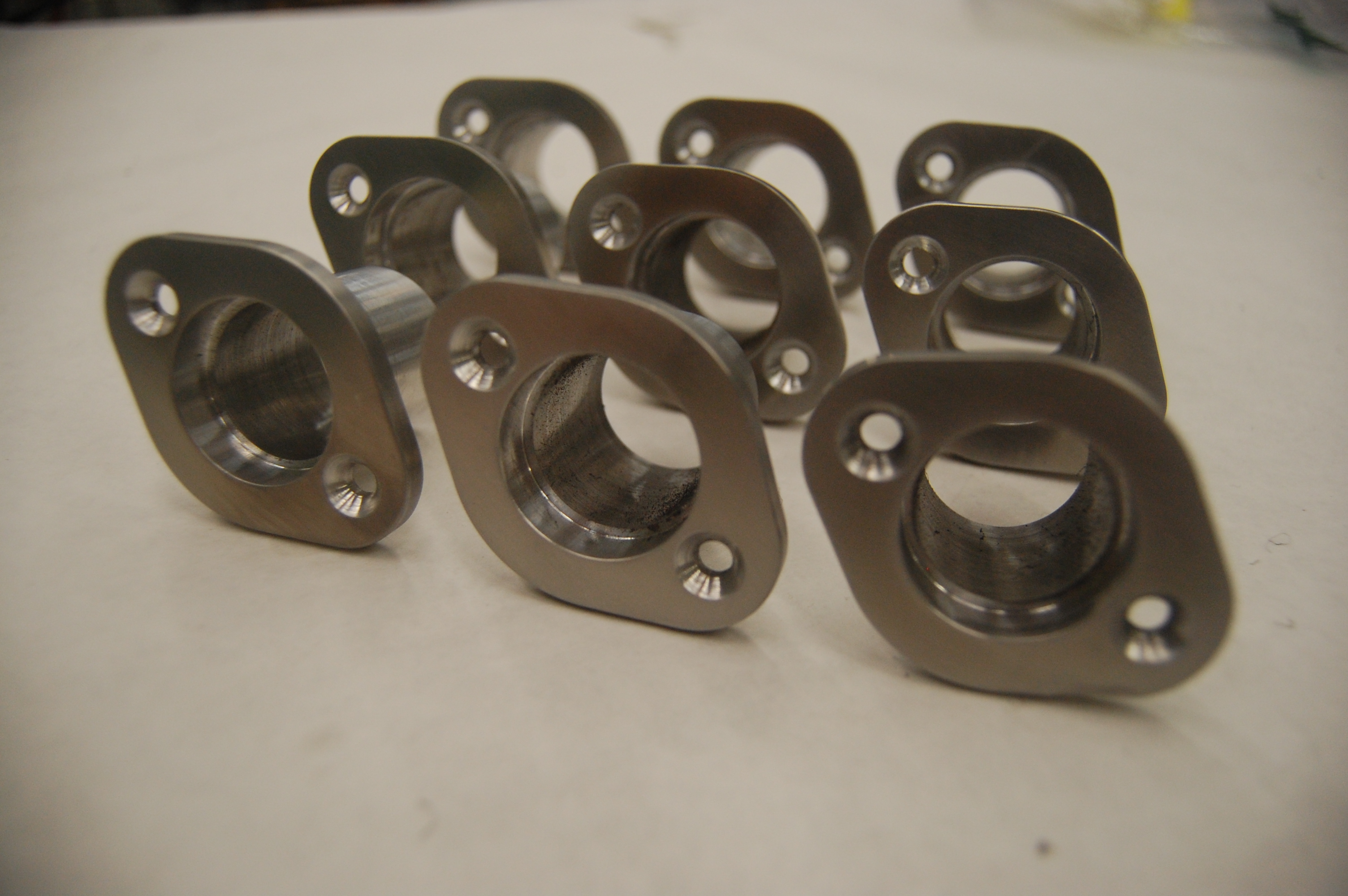
The center bearing housings for the drive base were finished and polished today. As a result the manufacture of additional parts will begin.
Action Items
- Continue testing shooter prototype
- Finish manufacturing new intake prototype
- Finish drive base CAD
- Send baseplate for manufacturing
- Continue designing rest of the robot
- Begin manufacturing parts for the drive base
Pre-SVR Day 8: New Shooter
Driver Practice
Today Driver Abhi Kumar and Backup Operator Jonathan Lee were able to get a lot of practice with the robot. Additionaly, Human Player Aaron Johnson was also able to practice with the drive team.
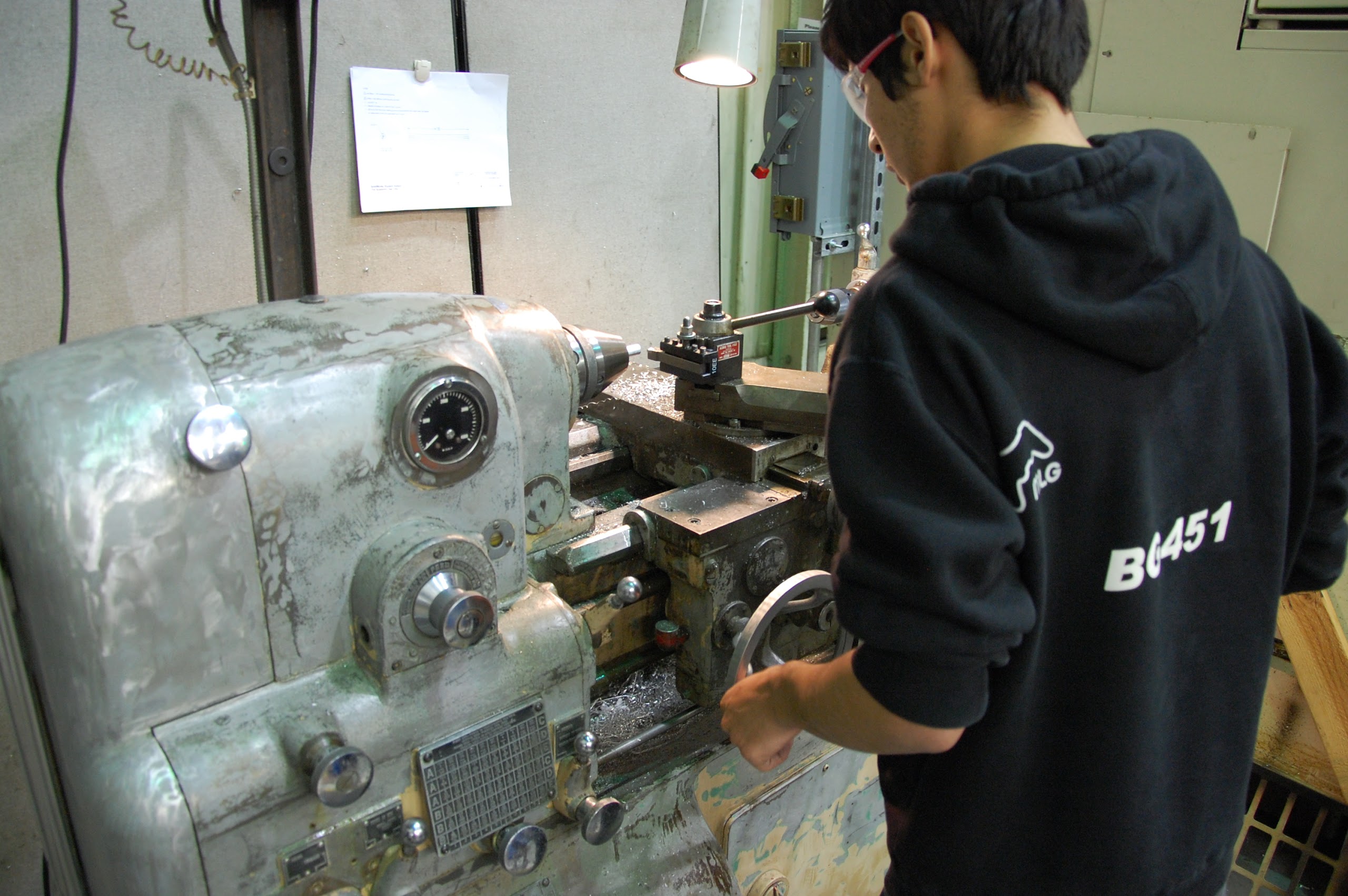
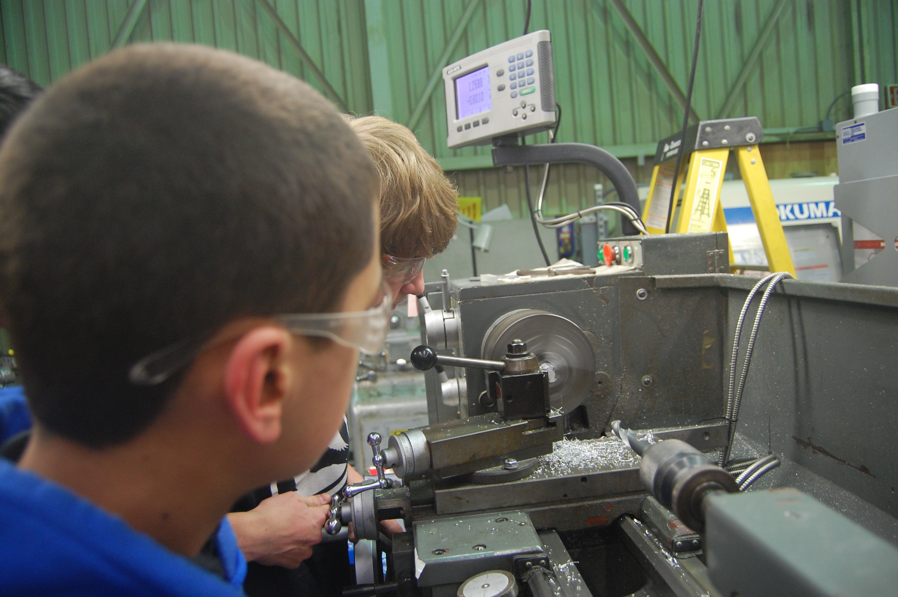
New Shooter
Students and Mentors began manufacturing and assembling the new shooter today. This shooter incorporates BaneBots 550 motors instead of Mini-CIMs, which were previously used on the shooter before. Students began by manufacturing spacers for the motor housing plate using the lathe and spare spacers from last year’s gearbox. They then worked on manufacturing the shafts for the wheels on the shooter. The components of the shooter were then put together and tested using the new shooter plates that were manufactured today.
Day #38: FRC Open Lab Scrimmage, Manufacturing, CAD
By Nick Mercadante
Lab Scrimmage
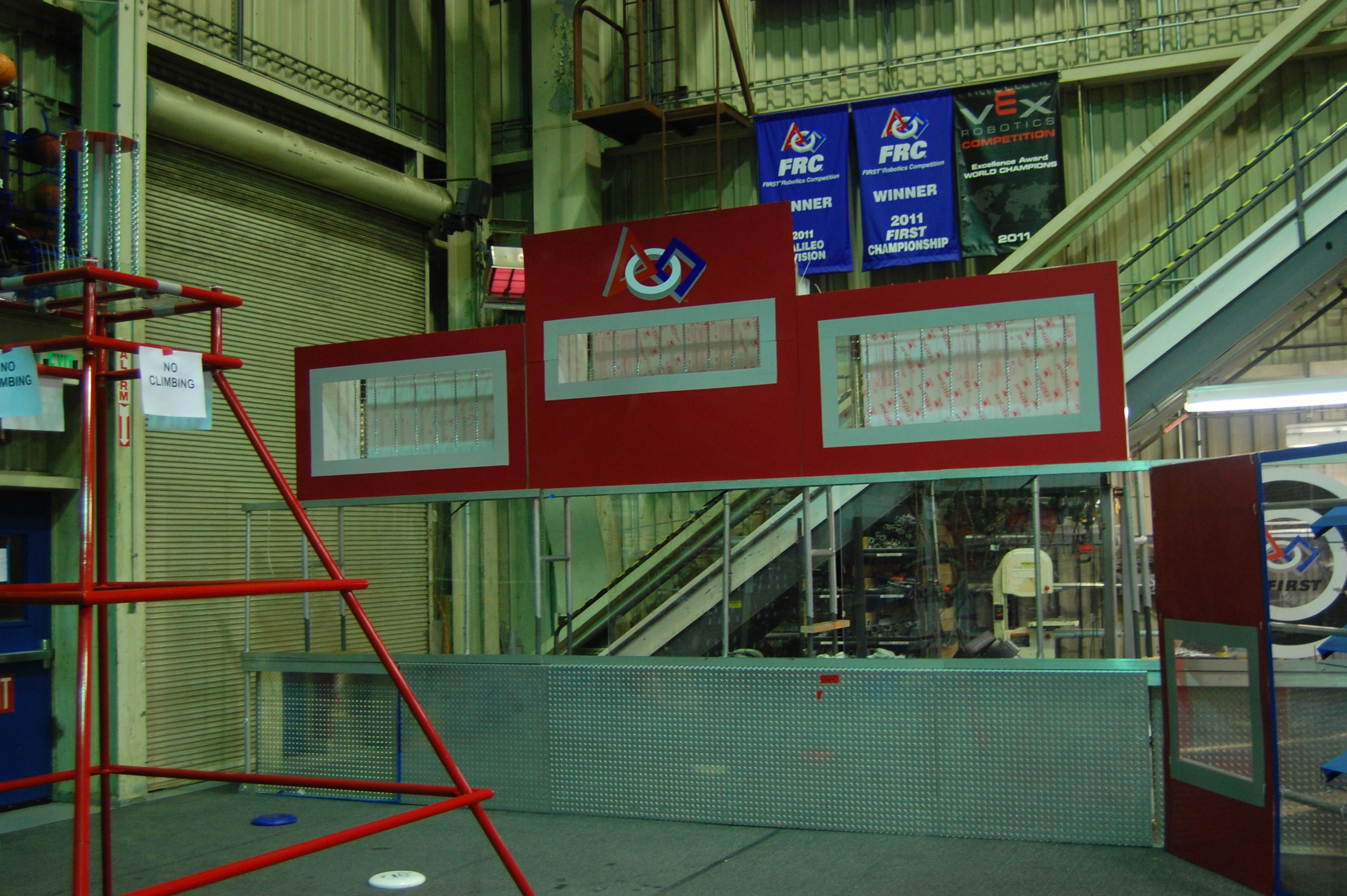
Today, the lab was opened to other FRC teams to let them practice on our field. They were able to practice hanging on the pyramids and were able to practice and adjust their shooting. The human players were able to get a couple throws in as well.
Manufacturing
While they were practicing on the Field, Students were working on attaching the latches onto the bumpers so that they would stay secure to the robot. Some adjustments were made to the inner indexing system so that it could feed the frisbee to the shooter at all of the angles that the shooter may be positioned at. Parts were manufactured for the hanger on the robot as well. The Practice Robot is almost finished and the competition robot is not too far behind.
CAD
The CAD for the Gearbox was updated to the current setup of the gearbox.
Day #34: Intake and Field Assembly
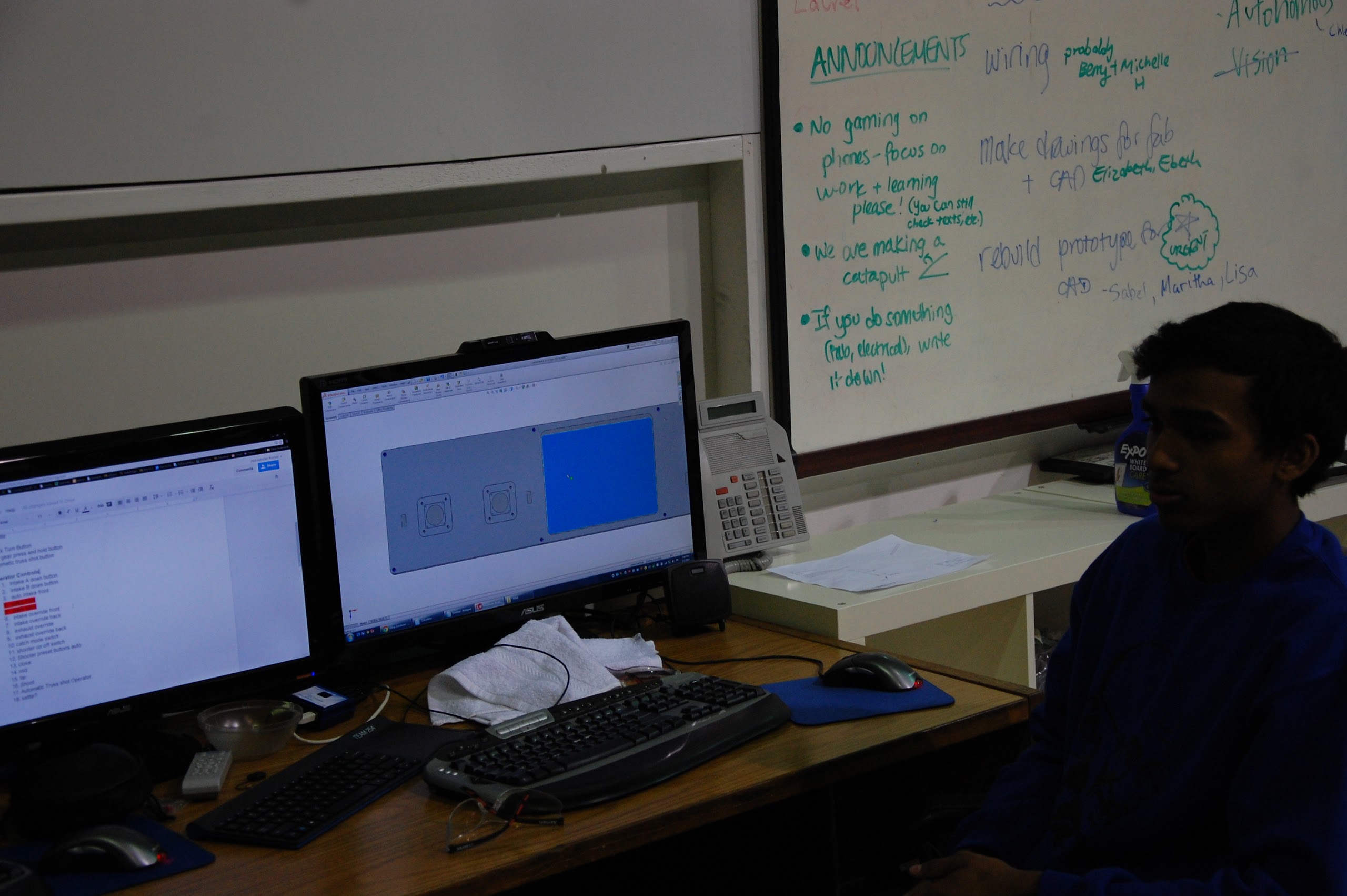
CAD
Today students went through the entire CAD and made sure that all of the necessary parts and materials to complete the robot have been purchased. To do this, he used a special feature in Solidworks that automatically created a bill of materials for the entire robot. He then cross-referenced this with our existing bill of materials to make sure that all the parts have been ordered. As of now, most of the parts have been ordered, however we still need to complete one more order with McMaster to obtain everything we need.
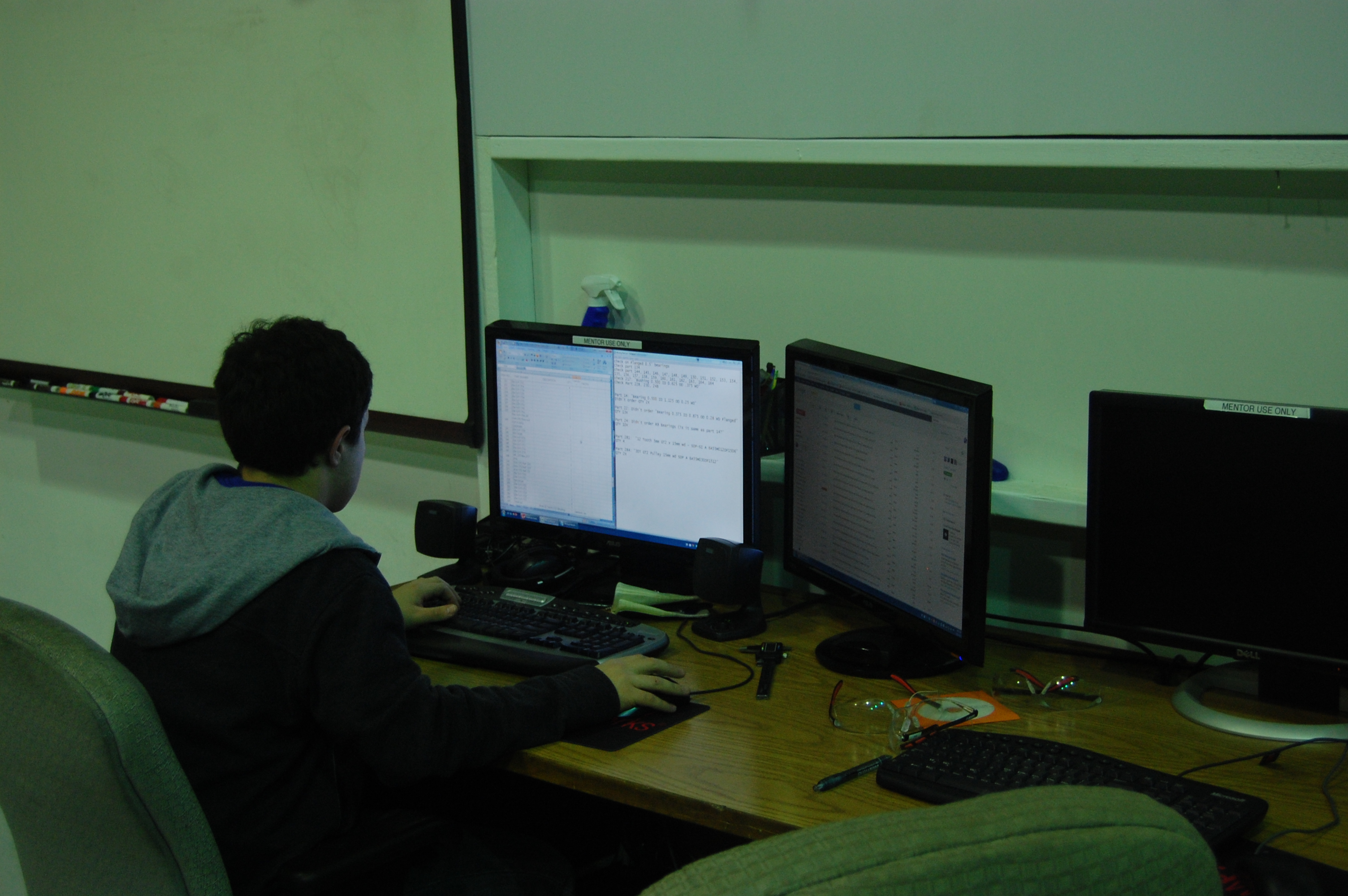
Nagy Hakim checking the Bill of Materials
Manufacturing
A lot of work was completed on the CNC today. Machining for the conveyor side plates is complete and ready for powdercoat. Machining for additional parts on the CNC, such as a structural gusset for the shooter, has begun.
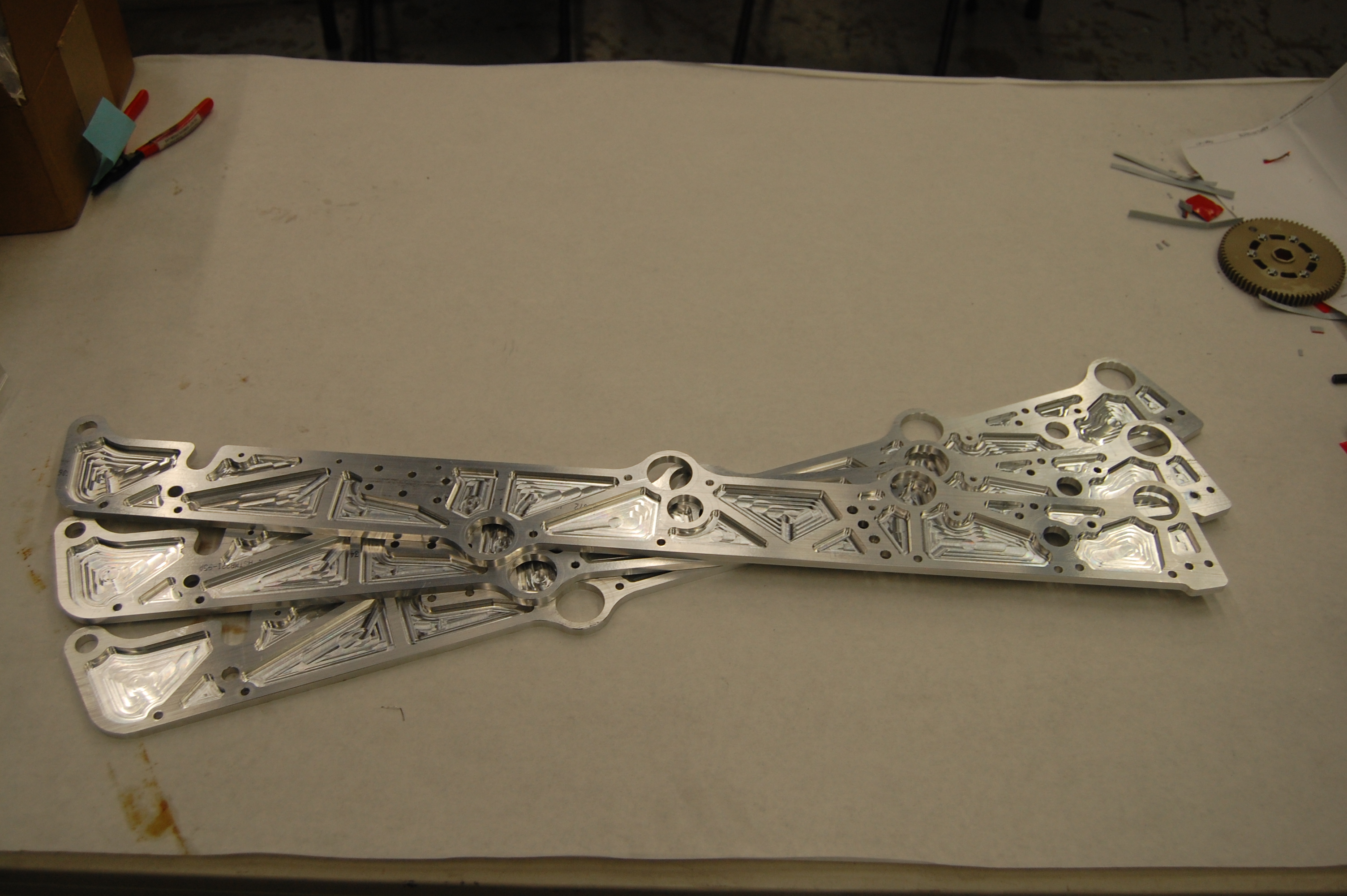
Finished Conveyor Side Plates
Additionaly, manufacturing for more shooter parts have begun. Students with the help of mentors finished machining the cross-pieces for the shooter assembly. These pieces will act as spacers for the shooter side plates and provide support for the entire assembly.
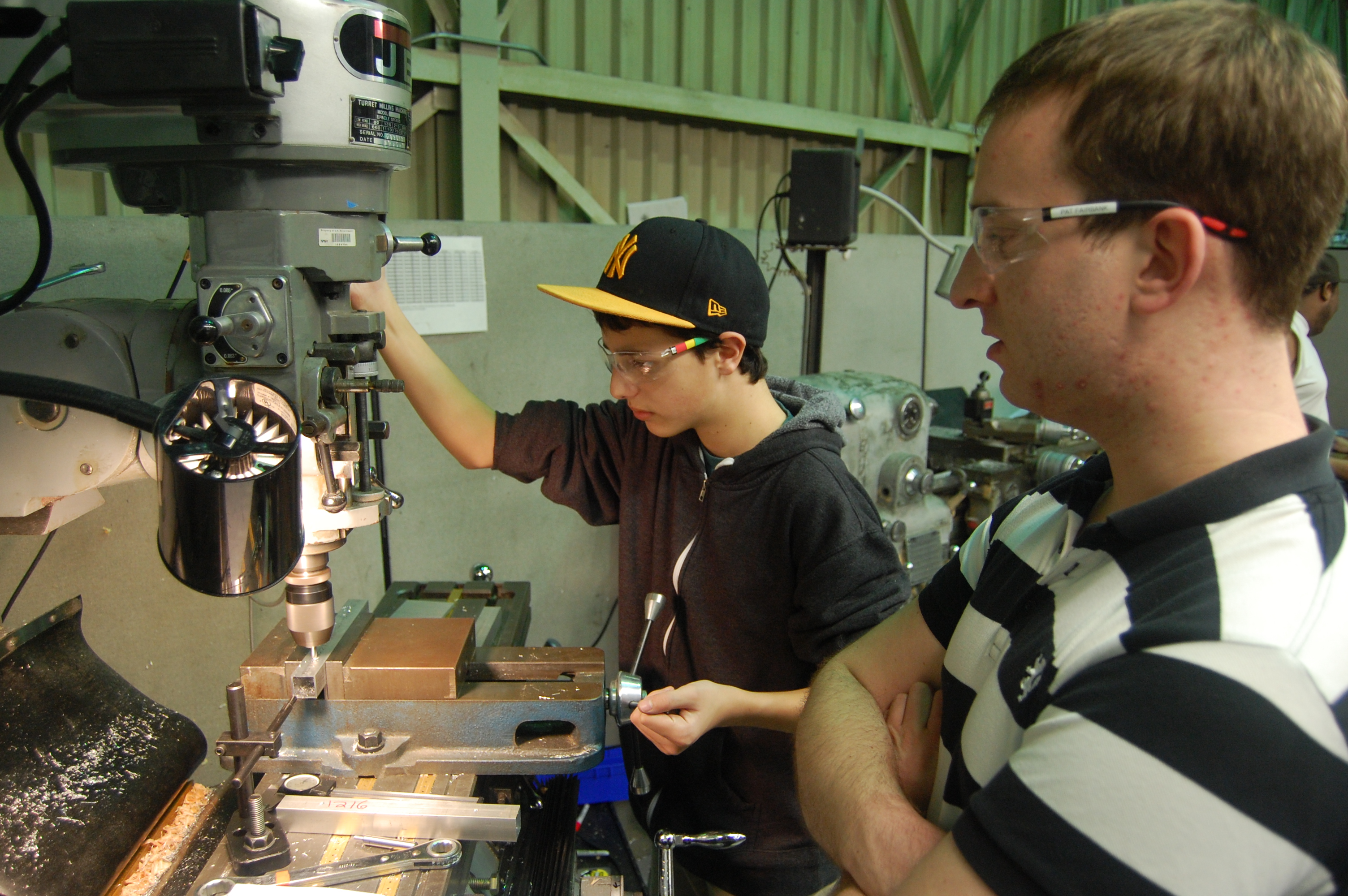
Precision Milling with Pat and Nick
Intake
Students with the help of mentors assembled the intake today. First, bearings were pressed into the intake side plates, and some were attached using bearing retaining screws. Then the rollers were fitted with BBD to help grip the frisbees. Team 254 debuted the use of a new BBD for the front intake roller, which is twice as large as the previous BBD used. Next, the intake gearbox was assembled and lubricated, and the was attached to a mini-CIM motor. This entire assembly was then mounted to one of the intake side plates.
Assembling the Intake
Addionaly, the intake was mounted to the practice robot for testing. Students along with the help of mentors assembled and lubricated the VEX pro planetary gearbox powering the mechanism lifting the intake. This is a special gearbox which will allow for a 100:1 gear reduction in a small volume, which increases torque. It also transfers energy coaxially, or along the axis of a shaft. A BaneBots 550 motor was attached to the gearbox, and this assembly was attached to the intake mount. At the same time, students countersunk VEXpro gears for the intake, and mounted them on the intake and the intake mount.
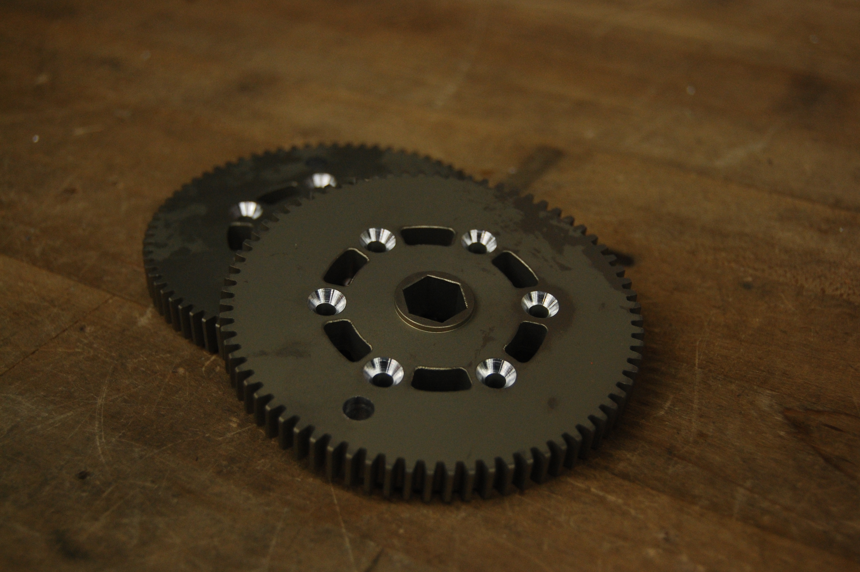
Counter-sunk Gears
 EJ and Jonathan mount the Intake
Field
Several students and mentors worked on fixing the structural supports for the goals that were created yesterday. Students first worked on creating new wooden shims to keep the vertical supports in the right place. They then worked on getting the structures on both sides of the field attached and aligned on the driver station wall. With Travis’s help, students also leveled the top of the driver station walls using a sawzall tool. This allows for the goals to lie flush on the supports. Students then worked on getting the goals mounted on the structures by first mounting the frames onto the structure, then placing the goals inside the frames. As of today, the red side of the field has been completed.
Art Kalb machining the wooden shims
 Students and Mentors align and mount the goals
 The Red Side is Done
Action Items
- Finish attaching Blue Goals
- Finish machining shooter parts
Lab Closing Time: 3:30 AM
Day #25: Manufacture of Conveyor and Shooter Begins
Drive Gearbox
The bulk of the remaining parts ordered from West Coast Products arrived today, including gears, shifting dogs, and shifter shafts. Students assembled the piston blocks for the bimba pistons. This will actuate the dog shifters, which will control the 2-speed transmission and PTO. The dog shifters were modified to prevent interferences and fit inside the gearbox.

Machined Shifting Dogs
Shooter and Conveyor
Students made drawings for shafts and spacers that will later be used on the shooter and conveyor. The raw materials for these parts were cut, and later manufactured by students with assistance from the mentors.

Makin the Pahts

Finished Parts
Programming
Students worked on the code for the intake. They also tested all the subsystems of code to make sure that they functioned properly.
Visitors!
Team 100 from Woodside, Carlmont, and Sequoia High Schools visited the lab today. They stopped by for a couple of hours to borrow the use of the lab’s hex broach.
Action Items:
- Assemble Drive Gearbox
- Continue manufacturing Shooter and Conveyor shafts
- Release more parts for manufacture
- Further develop code
- Wire Pneumatics
Lab Closing Time: 12:30
Day #6: Consistent Shooting Prototype
Design
Gearbox Design
It was decided that a power take-off (PTO) mechanism will be implemented into our drivebase gearbox design. A power take off simply allows all the power from the drivebase gearbox to be applied somewhere else. This is achieved by adding an extra output shaft to the gearbox with a another shifter, giving the gearbox 3 "speeds". There is the high speed, low speed, and "neutral" speed. Neutral will inhibit the wheels from receiving power and allow our hanging mechanism to be fully powered by six CIM motors (the most powerful motors in the Kit of Parts).
Implementing the PTO will give the hanging mechanism the maximum amount of power (since the motors allowed are limited) thus allowing the robot to hang as quickly as possible.
Today's progress included adding a third CIM motor to the gearbox and changing the configuration of the motors to allow for a second shifter and second output shaft.
This gearbox will be the biggest, heaviest, and most powerful gearbox Team 254 has ever built! It will be called "Big Daddy!" to compliment 2011's enormous intake gearbox, which was crowned "Big Momma"
Prototyping
Intermediate conveyor prototype
Students worked on prototyping an intermediate conveyor system which will be used to transfer the frisbees from the intake to a second mechanism which will transfer the frisbees to the shooter. The second mechanism has not been prototyped as of now. This prototype currently uses timing belts that are connected to two horizontal rollers. These rollers are currently running at 1400 rotations per minute. As of now the prototype works as long as it is tilted less than thirty degrees from the ground. When the prototype is angled more than thirty degrees from the ground, a pressure must be exerted perpendicular to the rollers for it to work.
Shooter Prototype
The shooter prototype was repeatedly tested, and it fires consistently when the frisbees are right side up. However the consistency is lost when the frisbees are placed upside down. As of now, we would like to add something that would prevent the frisbee from angling upwards before it exits the shooter.

Intake prototype
Students added bearings to the rollers in the prototype to prevent the loud clacking noise that occurs when it is operated.
Miscellaneous
Students finished the CAD for the LED Power Box and components. This will be assembled later and used for the pit area trussing.
Students built a mock-up human player station. They also determined best way to feed frisbees through the human player station and throw them across the field during the last thirty seconds of a match
Programming
With a new to-do list to keep track of action items, a multitude of programming-related tasks were completed or started. Students worked on getting constant variables to read from a file for the robot code. This updating would happen in robotInit(), right as the robot turns on. They also worked on reading autonomous scripts from a file for the robot in such a manner that these scripts deployable without re-compiling. Since they don't have the actual autonomous functions yet, programmers have created an initial structure to parse in names of the commands and their parameter(s) from a text file. The Smart Dashboard was installed on the driver station. Tomorrow, programmers will work on creating custom widgets to place on the dashboard. Lastly, programmers imported math functions from the 2012 robot code into the 2013 robot code.
Action Items For Tomorrow:
-
Upgrade Intermediate Conveyor Prototype
-
Upgrade Shooter Prototype
-
Continue Programming (See Richard's Action Item List)
-
Finish Drivebase CAD
Time Left the Lab: 12:00 AM
