Blog - March 2017
FRC Day 40 Build Blog
Day 40: Improvements for SVR
Driving Improvements
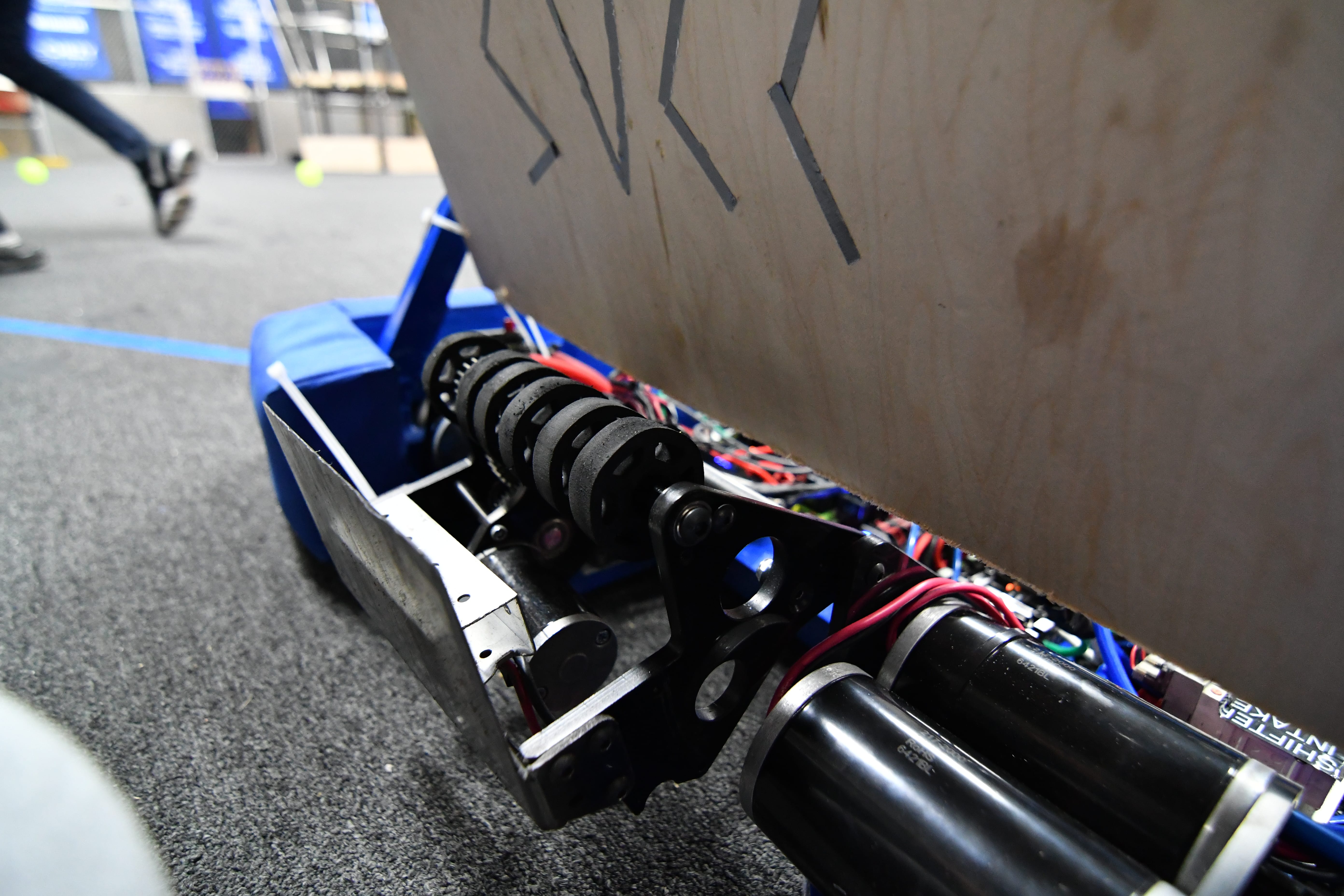
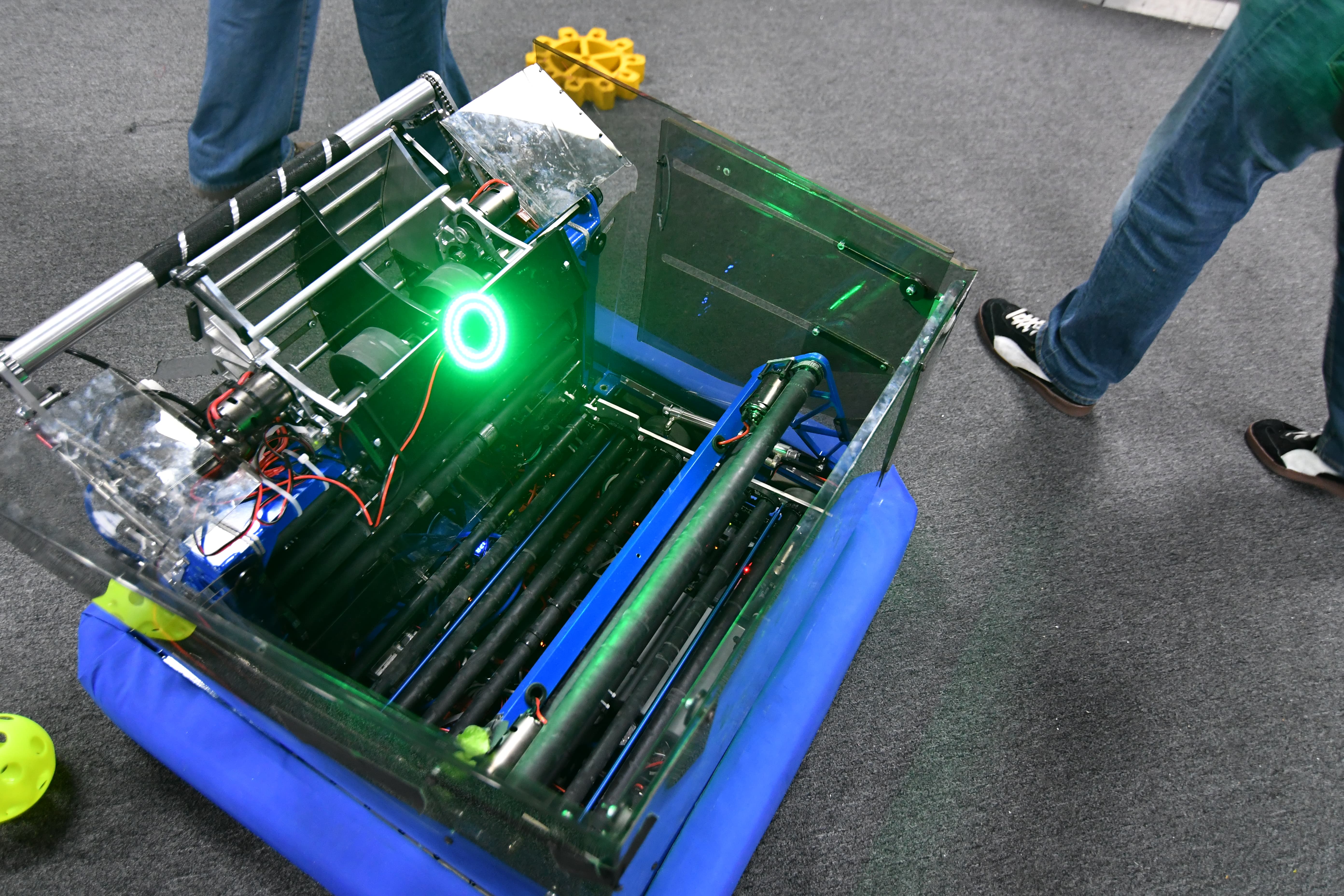
We added additions to our robot in order to create an easier and more efficient driving environment. We have placed a blue LED strip on the back of the hood to let drivers know whether or not they are in a good shooting proximity. To do so, we wired up MOSFETS to control the LED strip, which will plug into the DIO port on the roborio.
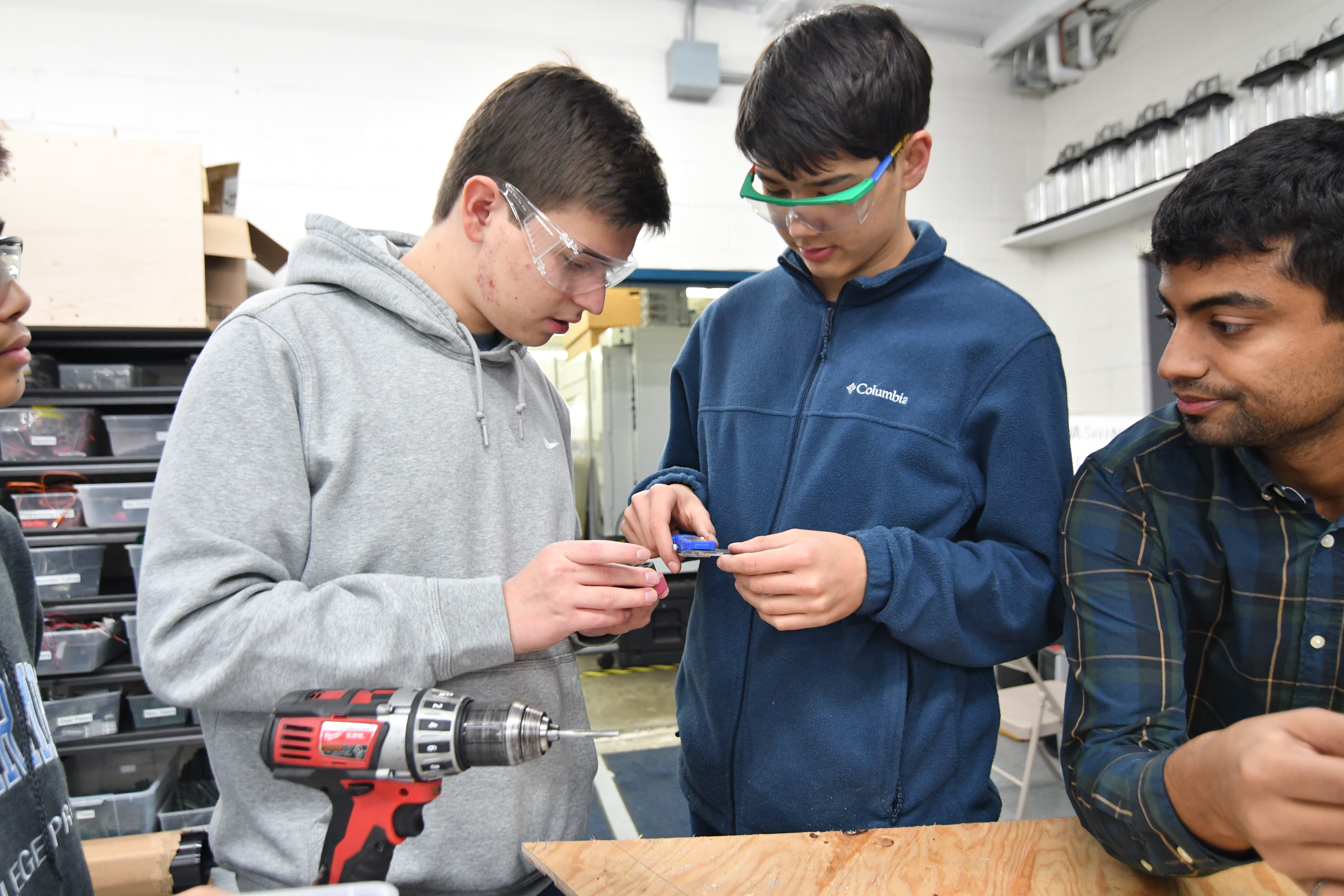
CamerasfAutono
At SFR, we found that installing “back-up cameras” would help with gear placement. Therefore, we worked on optimizing the camera placement, as well as finding a way to widen the narrow field of view (currently 70 degrees) to better capture the gear’s location.
Autonomous
After the post-mortem we worked to improve the robot's turning during autonomous. We prototyped small Delrin sliders that didn't quite work when sliding on carpet. We anticipate that the best solution will be to try to implement drop-down omni wheels that we can turn on. However, if that does not work either we will resort to changing the autonomous routine itself.
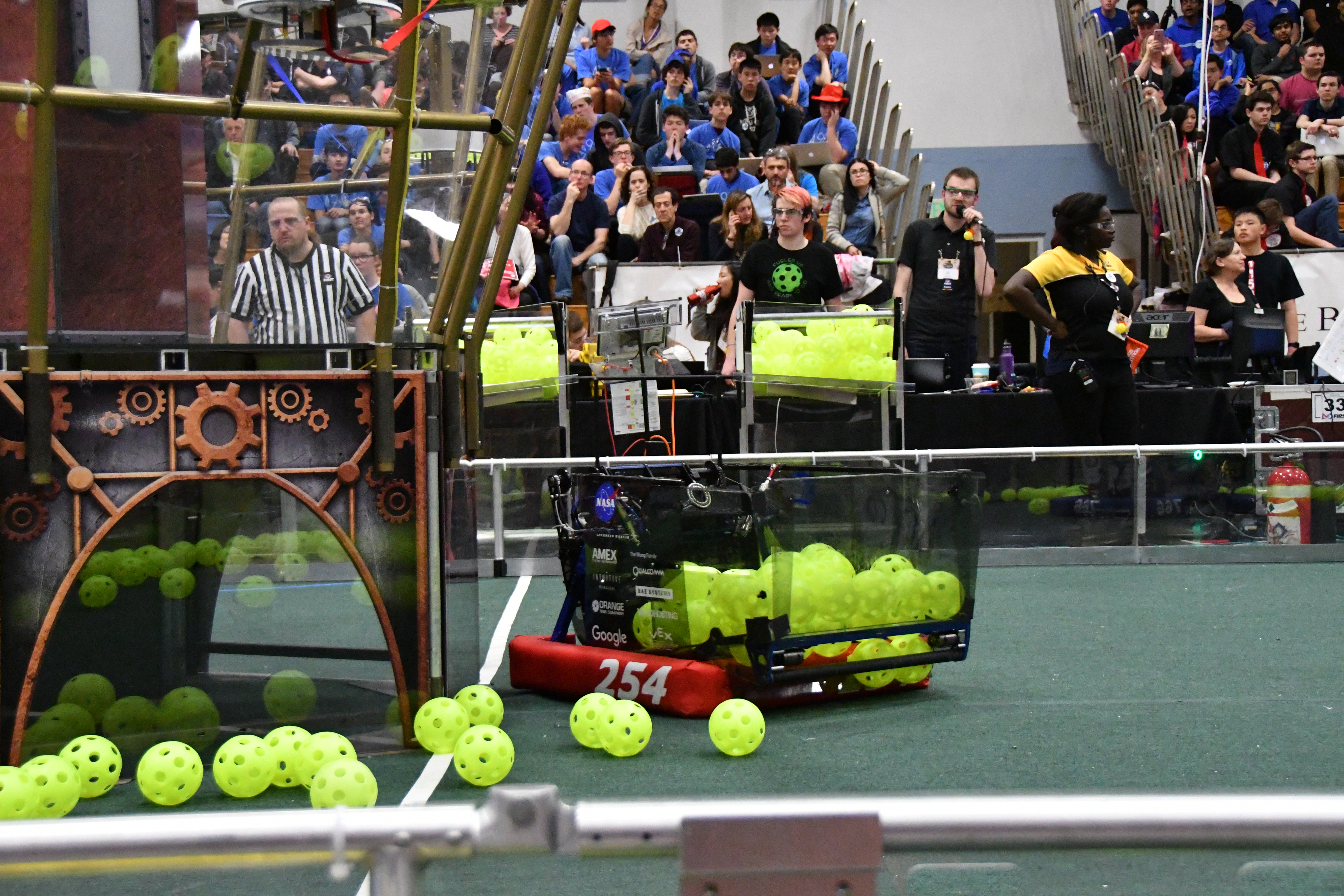
San Francisco Regional Tournament
This past weekend, we competed at the San Francisco Regional at St. Ignatius College Preparatory.
Qualifications
Throughout the qualification matches, Misfire performed strongly, going 10-0 overall and scoring an average of about 277 points. We focused on a strategy of reaching 40kpa to maximize the amount of ranking points we would receive, which worked out as we were seeded first heading into eliminations.
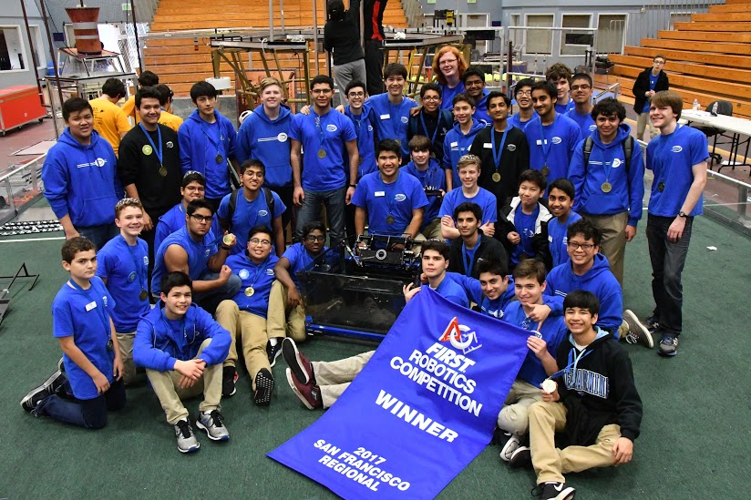
Eliminations & Awards
In our alliance, we picked Team 971 “Spartan Robotics” and Team 4990 “Gryphon Robotics.” With this alliance, we aimed to focus heavily on the high goals, hoping to get 40kpa+ in the boiler, 2 rotors spinning, and all robots hanging in an ideal game. We also planned to use defense, having one of our robots block the chokepoint near the gear loading station, hopefully making it impossible to for other teams to score 4 gears.

Throughout several exciting rounds, we ended up winning winning the tournament after an intense final match. We also won the Innovation in Control Award and Griffin Soule, our team president, won a Dean’s List Finalist Award. It was a great experience playing against all these teams and we hope to see some of them again at SVR.
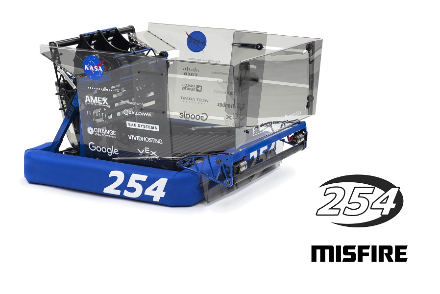
Misfire Reveal
Team 254 presents our 2017 entry into the FIRST Robotics Competition: Misfire. Misfire will be competing at the inaugural San Francisco Regional, followed by the Silicon Valley Regional and the St. Louis FIRST Championship. More information on the robot.
FRC Day 37-39 Build Blog: Preparing for Competition
Days 37, 38, & 39: Preparing For Competition
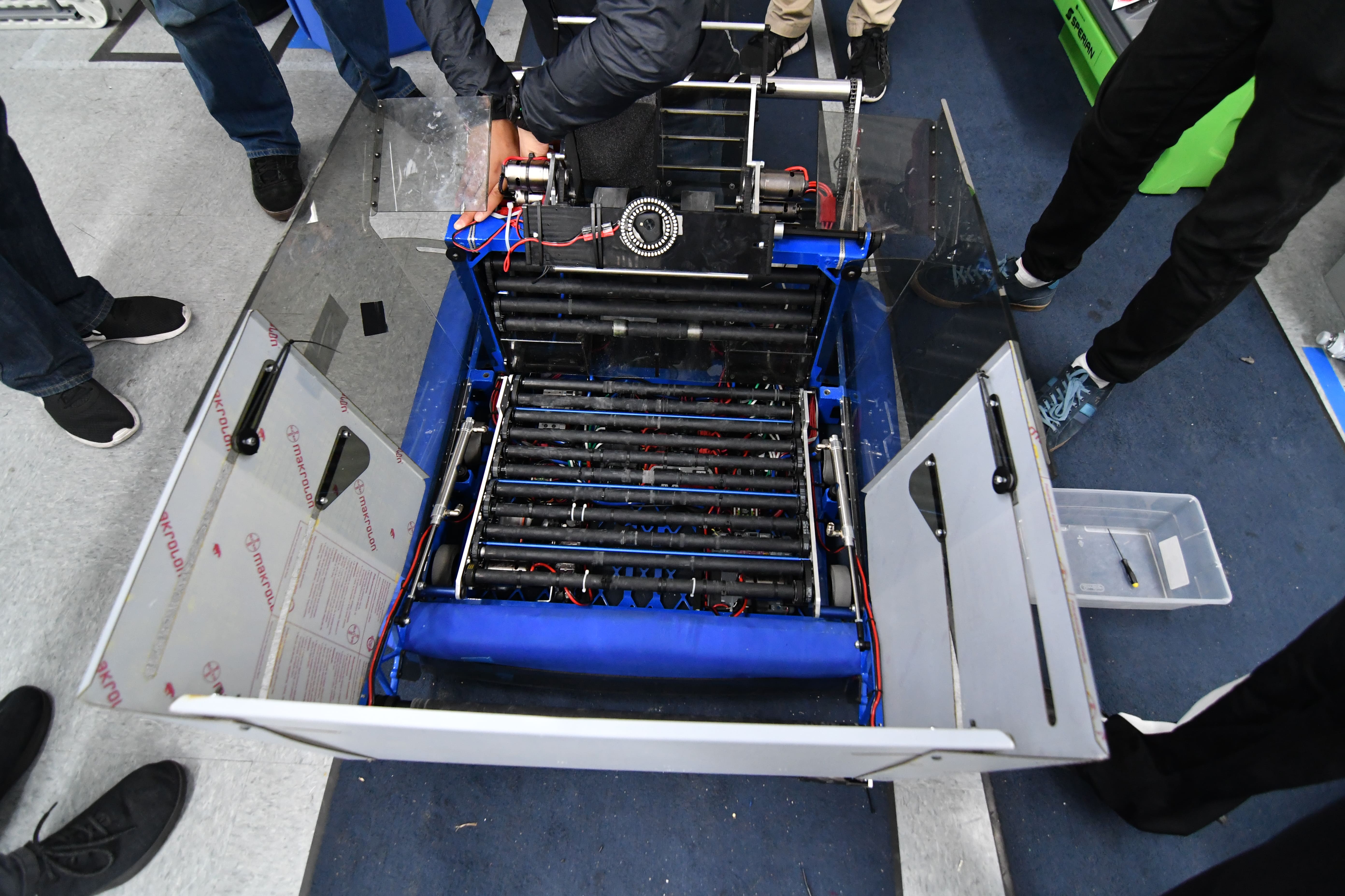
Intake
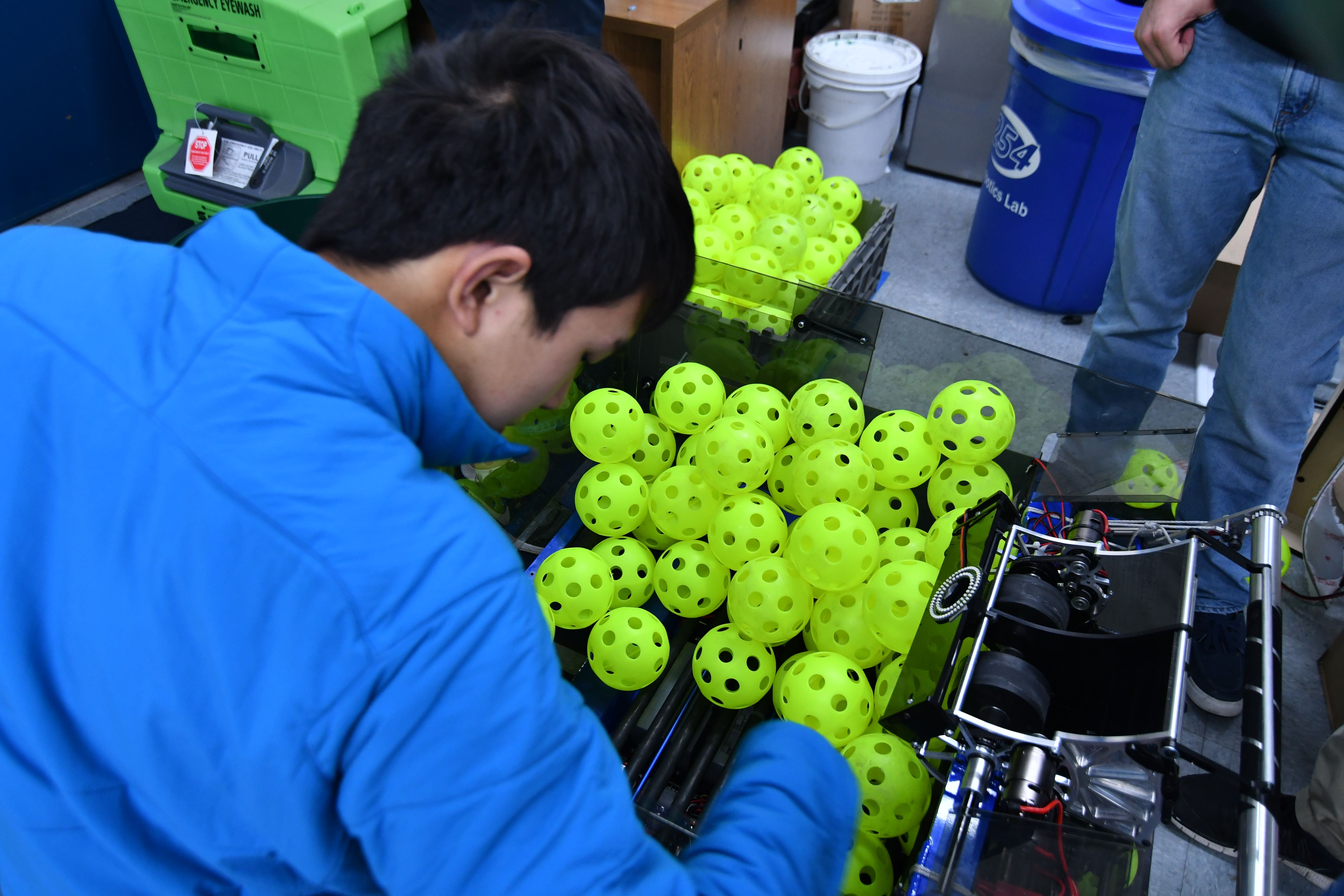
Today, we worked on fixing the intake after it broke earlier this week. After analyzing the strength of our current weldment and modifying it slightly, we decided that simply strengthening it would not help the fundamental problems existing in the design. We took one of the broken intakes and attached it to new polycarb side plates hoping that this would decrease impact forces by increasing the time of impact (change in momentum = force * time). We drove around and crashed the intake several times with minimal damage occurring, and we are proceeding with the new design.
Hopper
Today, we worked on the Hopper and testing the fully assembled redesign. After fixing some initial discrepancies in the real life assembly, we tested out deployment and stowing. As of a few tests, the intake deployed well (after modifying the intake ramp slightly to have slightly deeper notches to fit the constraint screws in) and we will be updating the CAD with these changes on Friday. We will also laser cut a new intake ramp to get definitive results. If all systems work well after that, we will begin assembling the new parts for comp as well as a back up.
Between, Friday and Saturday, we were able to finalize the hopper design. After some CAD work on the redesign and some troubleshooting after assembly, we were able to make a solid hopper. More testing will continue to confirm consistency, but we will be moving forward with the Comp set soon.
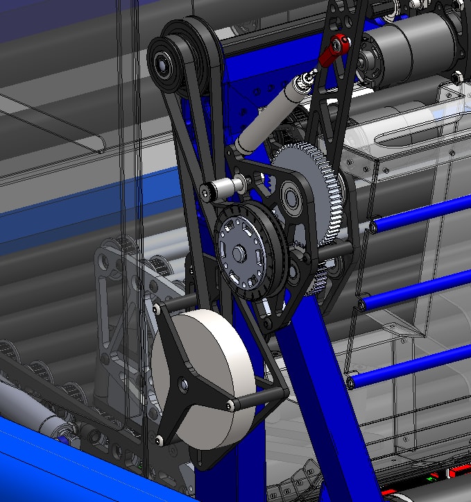
Shooter Flywheel
In the last week, we explored the use of a large flywheel to help increase the consistency of the shooter. A flywheel dramatically increases the kinetic energy of the shooter wheel system, hopefully reducing the amount that the wheel slows between shots. We designed a steel flywheel with about 4 lb*in2 of inertia. It is geared up 2.5:1 from the shooter wheel to increase the kinetic energy. Preliminary testing shows that adding the flywheel may not actually achieve the desired result. The elasticity of the timing belt caused some controllability challenges that the programming team worked on this weekend. Each time the direction of tension in the belt switched (from energy going into the flywheel to energy leaving the flywheel), there was a little bit of elastic movement which added oscillations to the shooter wheel system. The plots looked like the typical mass/spring/damper plots for a 2nd order system from a controls or dynamics class.
 Climber
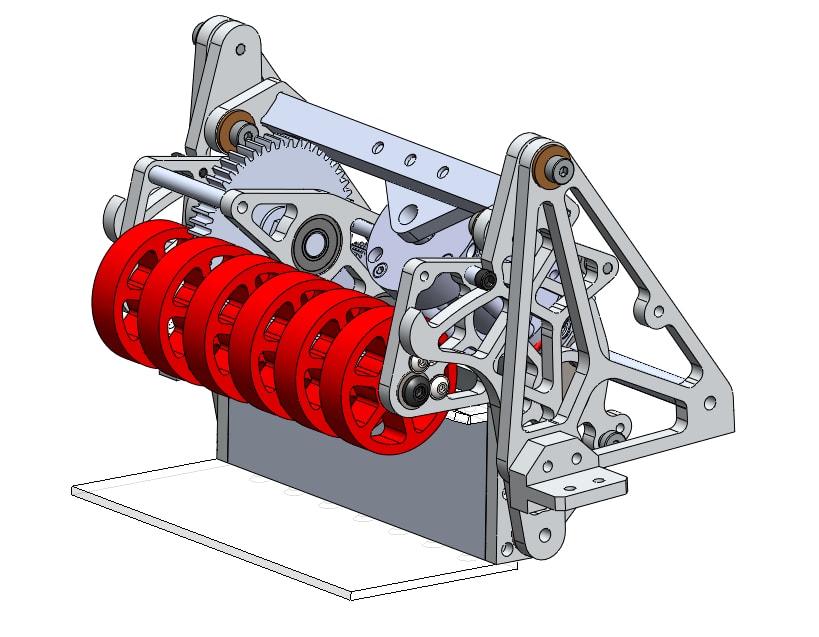
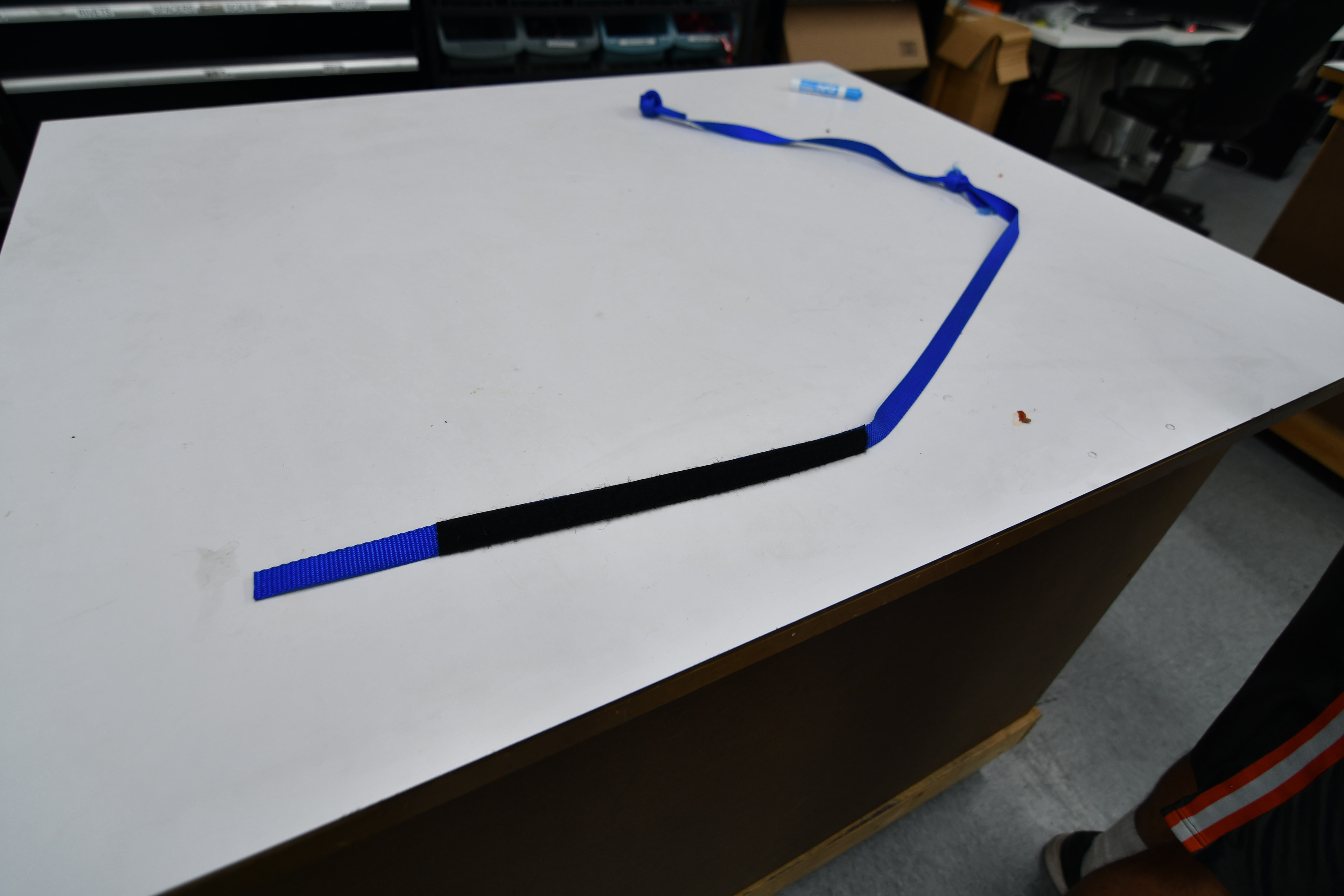
We are using inline elastic to add stretch to the rope. This will allow the robot to pull the rope down with a low amount of force at first, getting some wrap before beginning to lift the robot off the ground. This is important because the Velcro that engages the climber drum is strong in shear – and its strength is proportional to surface area. Once the rope has wrapped around the drum enough, the load transfer switches to Capstan forces. We are assembling several ropes, each with a number of pockets like the ones shown below.
A video is linked below of the climber being tested. Note that in this test case, we were pulsing the motors. Typically, the climb is much faster.
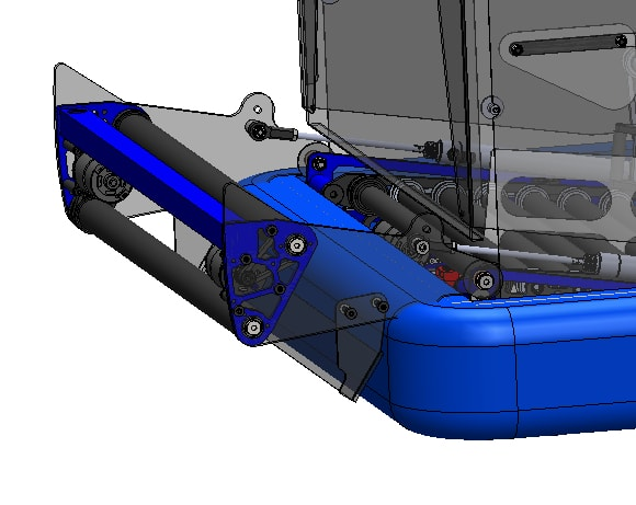
Gear Grabber
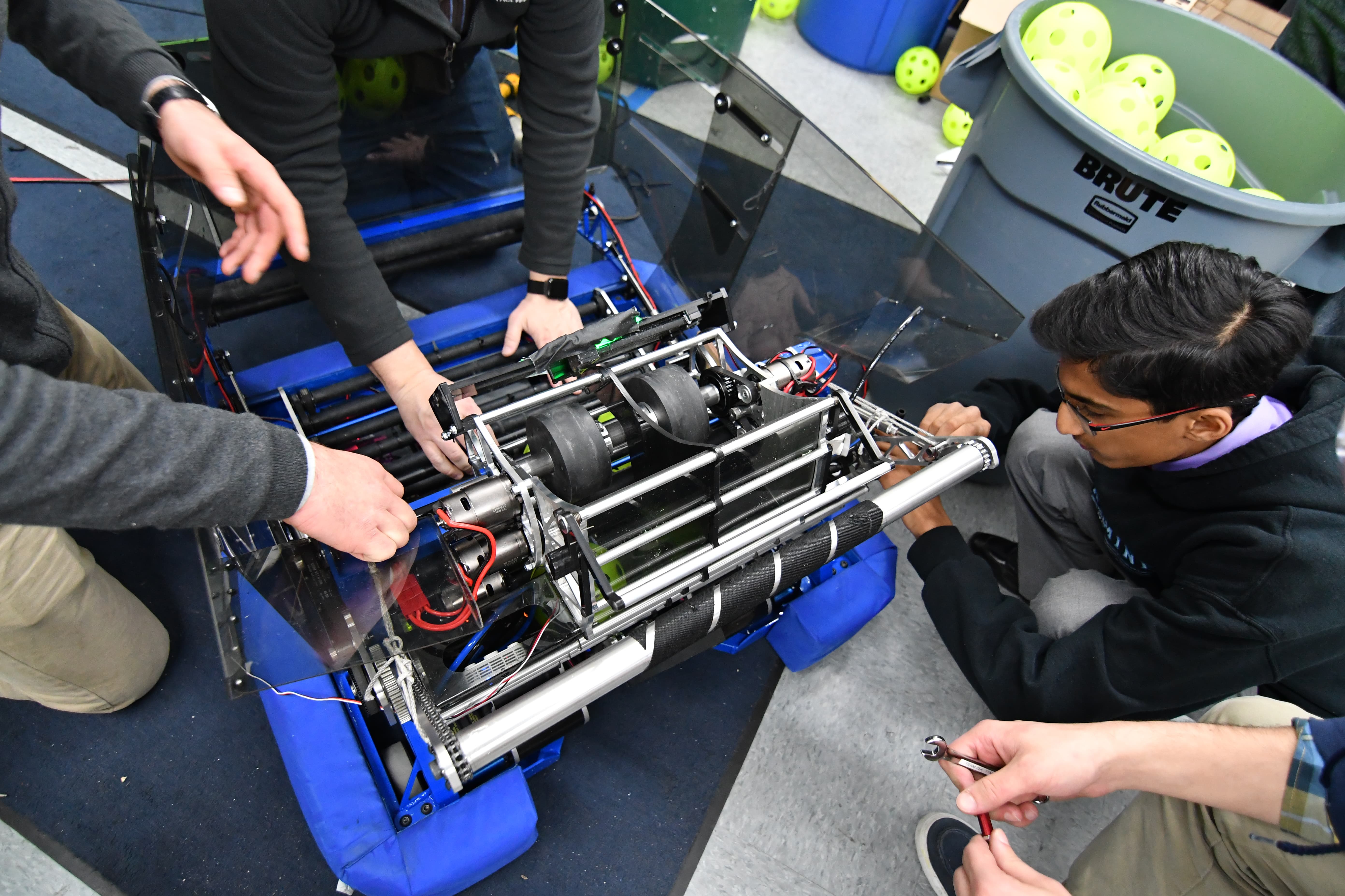
The latest iteration of the gear grabber has a dual pivot design – the whole mechanism pivots from a pickup configuration to a scoring configuration with one pivot, and a second lower pivot is sprung to allow the wedge to conform to the floor without digging in. We built this prototype last week out of delrin on the laser cutter and used it for driver practice over the weekend. We moved forward with making this out of metal and sent the parts to Anodize on Monday morning.
Check out the video below for pickup and scoring performance of the current prototype:
Driver Practice
We practiced driving by cycling gears with and without defense, climbing, and intaking balls off the floor. We are much better now at quickly scoring gears, and in one practice match we scored 9 gears and climbed when no defense was played on us. The gear grabber is much more reliable, and consistently picks up gears off the ground the second we touch them. Scoring is still tricky, but we are getting better at finding the right depth at which we need to drive into the spring.
Programming
Autonomous Program
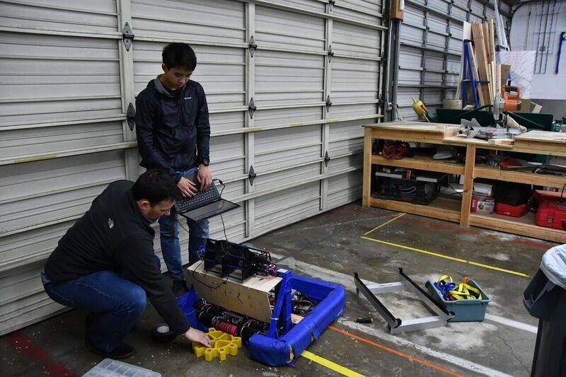
Today, we worked on finding and fixing a bug in our Adaptive Pure Pursuit controller. The bug was causing arc lengths in the controller to be calculated incorrectly in some cases, resulting in a value much higher than it should have been. This would in turn cause the robot to drive way too fast and shoot past the end point in the path.
Gear Grabber State Machine
Today, we worked on implementing a new Gear Grabber state machine. The new gear grabber code greatly simplifies the operator controls. Now, there are only 2 buttons used for intake and release. The state machine uses output current to determine when a gear has been picked up and will activate the piston automatically.
More Information
We also found two bugs resulting in the robot not turning left and twisting along an autonomous routine, and we were able to fix these edge cases.
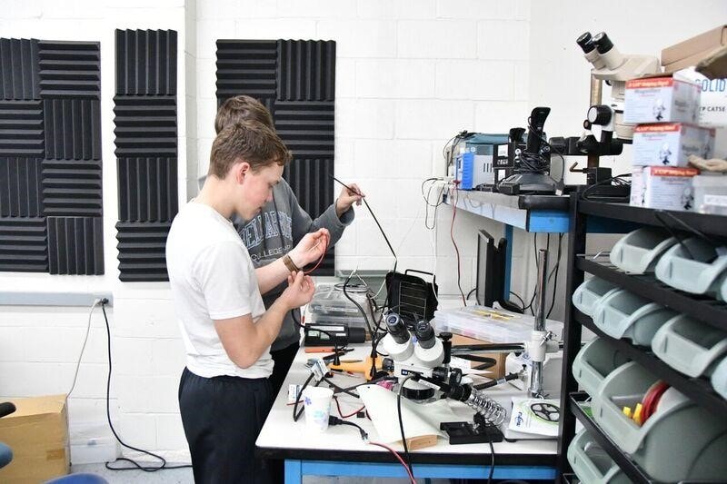
The hardware team began crimping and attaching 15 battery leads and running battery tests to determine true battery capacity.
FRC Day 36 Build Blog
Day 36: Improving Subsystems
Hopper Floor
Today we ordered all the the parts for the upper extension of the hopper floor and got majority of the CAD done. We will be going with 50 degree edges made out of Delrin with the first two rollers of the upper extension not having any surgical tubing to allow for horizontal movement.
Feeder
Today we worked on inventorying all the COTS parts for the Feeder subsystem. This would allow us to become more organized and make sure parts we need we have or are buying. I also helped lead students in inventorying other subsystems via the CAD,
Gear Grabber
We worked on the gear grabber. We removed the polyurethane added before with black, conforming WCP wheels. We found them to work significantly better than the polyurethane, but still not extremely well. We continued to work and changed the WCP wheels to red conforming wheels, which while ugly, worked better.
FRC Day 33, 34, & 35 Build Blog
Days 33, 34, & 35: Preparing for Competition
Gear Grabber/Driver Practice
We worked with the drivers over the weekend, doing basic drills like gear cycling, in order to become accustomed to driving the robot prior to the SFR Competition. We started the day by iterating on the floor for the gear grabber. The floor pickup for gears still needs work as it is inconsistent at picking up the gears when we drive into them. The polycarbonate knife edge was not as smooth as the prototype. There was a small edge on the actual version which was causing problems, so we sharpened it. After iterating on it, we then mounted it, and set ourselves on solving the jackknifing. We realized the best solution for this would be to redesign it, so Andrew and Mani are working on a new CAD. Meanwhile, the group worked on iterating on the length of the polycarb. We still have work to do before we finalize the design.
Bumpers
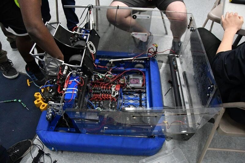
The major problem we were trying to solve was that the bumpers were too low. This was because the mounting solution uses C-channel brackets that go around the bumper supports and are supposed to sit flush to the underside of the little 1/2 x 1/2 bumper rail. But, what we didn’t realize is that the rail actually has a weld bead under it so the brackets could not go up high enough. This made the bumpers too low to the ground. To fix this, we removed a couple staples and pulled back just a bit of fabric on one of the practice bumpers so we could remove the brackets without actually remaking the entire bumper. We used the mill to make the brackets shorter, so they can move up and avoid the weld. We also used the drill press to add a new hole so they can align to the holes already drilled in the robot. This works pretty well, but some concerns are that the bumper is now too high and lifting the intake up, preventing it from going down far enough to have good compression on the balls. As of now, the intake is working fine. We still need to mill down all the other brackets, and we talked about making new ones and getting them anodized for the competition bumpers. The red comp bumper still needs fabric, and the blue one should have the fabric removed.
Hopper
Over this weekend, we worked on the hopper redesign. After some initial tests, we found that perhaps preventing the hopper from expanding sideways in the front expansion might add rigidity and strength to the hopper. To do this, we tested by bolting the front sliders to the hopper to prevent them from sliding. After testing, however, we found that intake by actuating the field hopper became difficult as the decreased width of the hopper prevented the balls from coming into the robot. To accommodate this, we redesigned the hopper in CAD so that the top will slide out vertically while the bottom pivots about a fixed point that torques the flexible polycarbonate. We also started the CAD of the new hopper floor for SFR which has the top rollers and wedges and a center to increase our ball throughput. We started the construction of the wedges on the hopper floor. After some brief testing, we CAD-ed this out. We will begin manufacturing on Monday.
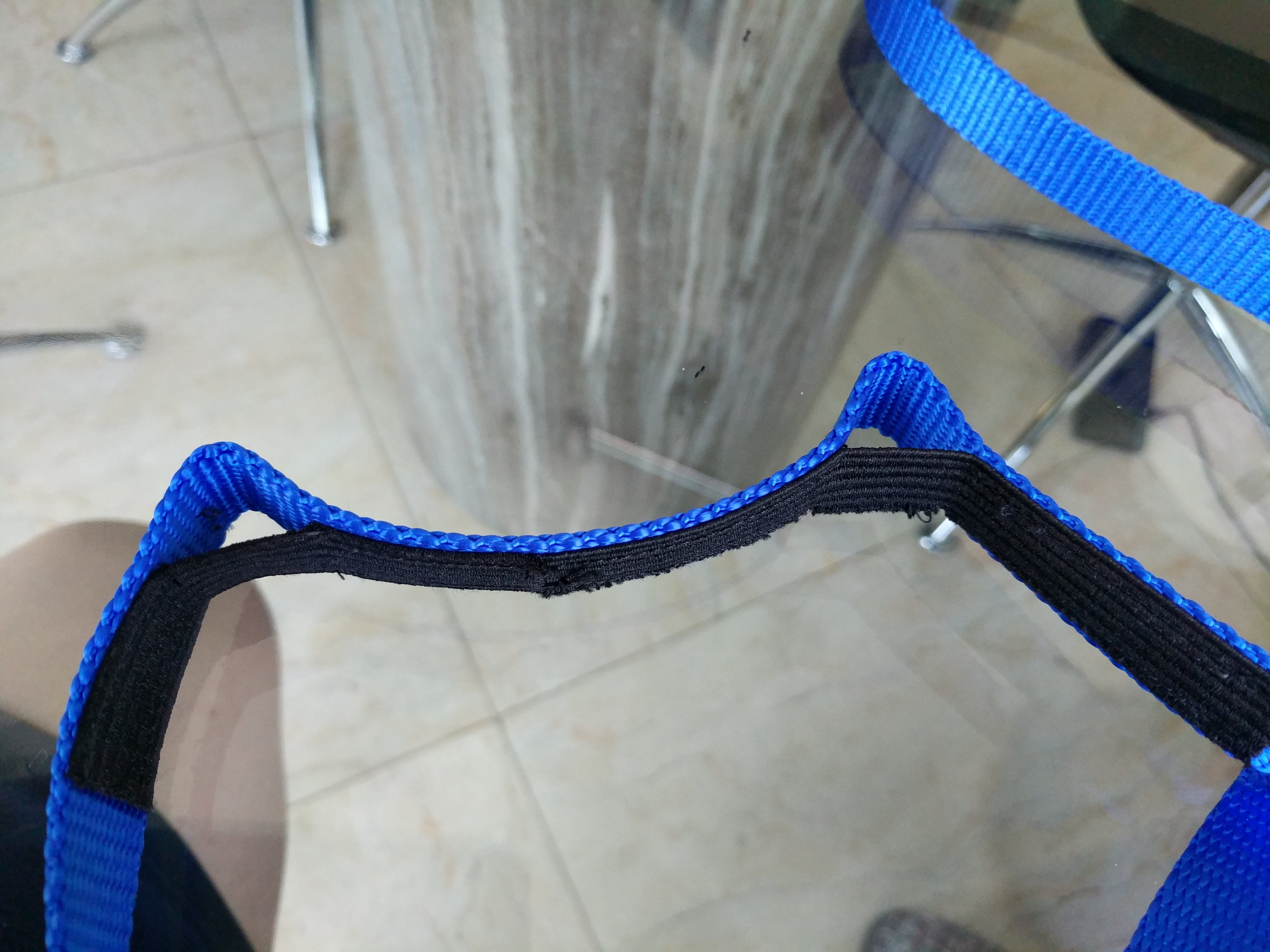
Hanger Rope
This weekend, we received the 3/4” ratchet strap climbing ropes with the sewed on velcro. We tested it by pulling on it and rubbing it at corners in order to see distressing. The rope was then tested using the rope climber on the practice robot but the lack of stretch/slack made it hard to latch onto. In the near future, the rope team will attempt to plan out elastic placement on the rope.
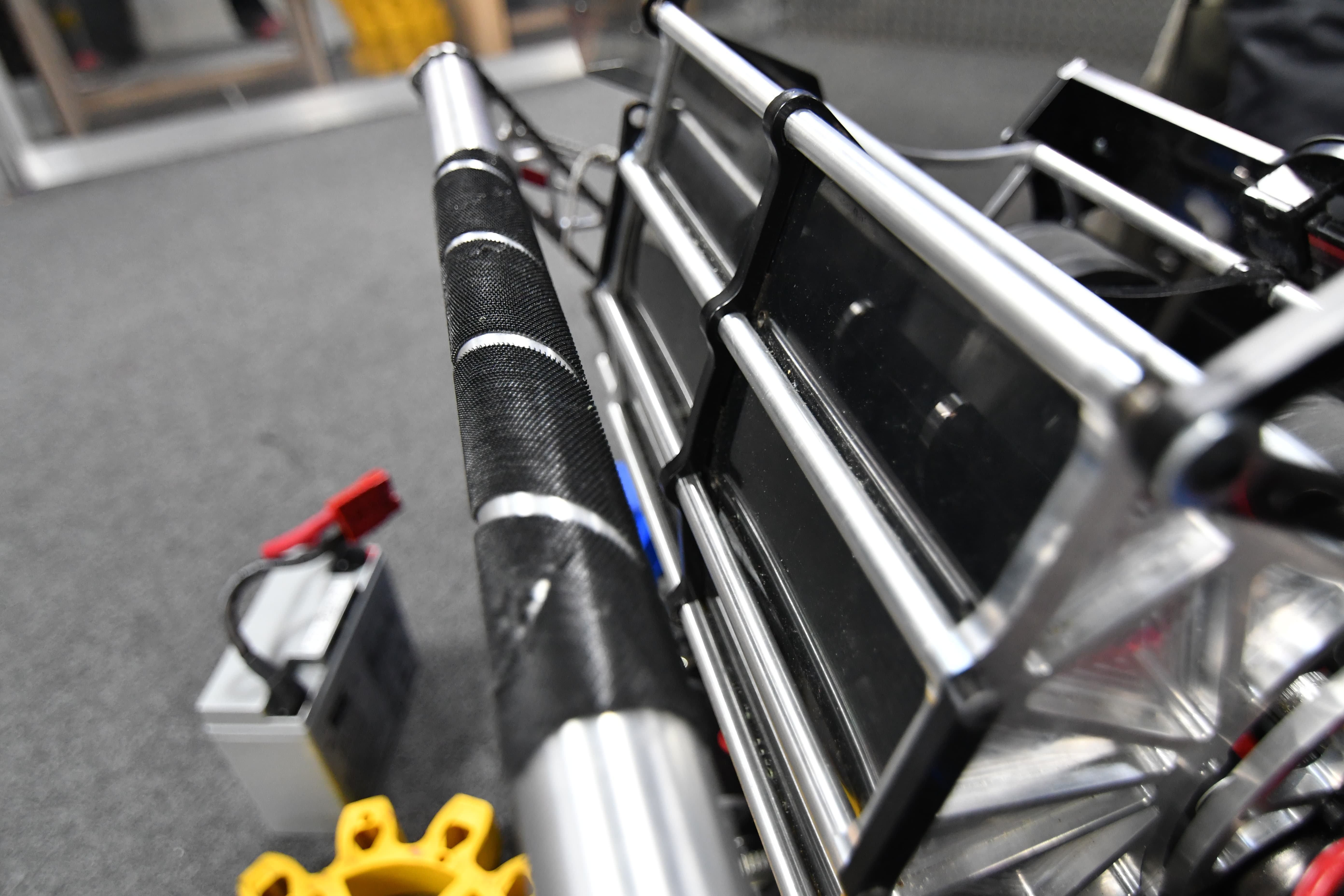
LED Light
We wired up a MOSFET to control the switching of the LED light, located on the front of the robot, by having a voltage signal sent out from the relay port of the Roborio. It allows the drivers to see better when having to place a gear without the light blinding them.
Programming
Autonomous Program
Today, we worked on creating a reliable 40 kPA autonomous mode. We decided that previous autonomous modes that used complicated S curves to swerve into the hopper were too inconsistent, so we settled for a new, much simpler mode. But, at the end of the night, we had a working auto mode that deployed the intake, rammed into the hopper head on, waited a few seconds for balls to pour in, then aimed and fired the balls into the goal. We continued to improve the efficiency of this autonomous mode until we had it begin shooting around 6.3 seconds or less. We needed the autonomous mode to begin shooting as early as possible because there is around a 5 second delay between scoring a ball and having the scoring system pick it up. Because of this, any balls shot past 10 seconds will probably not be scored during auto.
We continued revising our robot's autonomous routines, and we were able to drive to the hopper and trigger it, receive a payload of balls, and fire into the boiler.
We also worked on a live data plotter that could plot robot data much faster than SmartDashboard. Various subsystems, such as the drivetrain, simply push data to a server, which pushes data to a grapher website on the driver station. This utility will be useful for tuning drivebase and shooter PID, as well as other programming tasks.
FRC Day 32 Build Blog
Day 32: Continued Assembly and Programming
Gear Grabber
Today, we worked on designing and testing the roller gear grabber. We installed a prototype onto the programming robot, and it worked somewhat well. When we drove into a gear directly, it was always ours, but it was narrow and difficult to always aim correctly at the gear. We played around with passive funneling, but were unable to significantly improve the width from which we can intake because of the sidewalls of the rollers were too low. Griffin and Colin are currently designing a new gear grabber that will likely funnel more effectively, and we plan to have it on the robot and testing it on Friday.
Hopper Floor
We took the top roller prototype that we have been working on, and added a center wall. The one from Monday was not long enough, so we extended it and stiffened it. We found this to help immensely. We also added zip ties across rollers to help the balls move across faster. We have reached a point where we are comfortable and confident with the floor.
CAD
We made progress on the hopper improvements in CAD and the redesigned Gear Grabber. We determined the geometry for the gear intake, designed the gearbox, and made the basic assembly that will be developed upon later.
Programming
Today, we worked on improving the web interface for the autonomous pathing tool. We improved the overall aesthetic of the app, and added several new features. These include the ability to see robot start and end rotation, and having the path colored based on the current speed of the robot.
FRC Day 31 Build Blog
Day 31: Continued Assembly and Programming
Hopper
On Monday, we worked on making the hopper more rigid as well as tackling other issues with it, including breach of size constraints and inability to actuate field hopper. We brainstormed and tested off of current practice-bot hopper with small team to determine solutions. We plan to change the front extension components to prevent them from expanding sideways by making it one piece. We will also lower the hopper to fold over the intake to give it greater strength and rigidity. As a result, the hopper will fold have slightly less volume for ball storage, but much greater strength.
Rope Climber
The rope design has been prototyped. The length and placement of velcro on the rope as well as the knot have been measured. The rope has not been tested or sewn on with velcro yet. Next build, we will attempt to prototype elastic and the placement of elastic on the rope as well as the amount.
Hopper Floor
We constructed a new top roller for the hopper floor. We also made few wedges at different angles to see which angle was best in directing each ball towards the shooter. Once we find the ideal wedge angle, we tested it. It worked well during the first test, but it was not consistent. Next time, we should keep experimenting in order to find the proper wedge angle.
Programming
We continued testing a ball counter for the shooter, but we were not able to count balls fast enough with the shooter on full power. For the counter, we’re using a Sharp distance sensor and creating a threshold that returns true when a ball is within range of the sensor. It is likely that our voltage threshold for the ball counter is too wide, causing some balls to not be detected.