
Blog - January 2010

Control Board
Update: Here’s the newer revision of the control board. I’ve added an ethernet port and a female barrel plug for the Classmate PC.

Here’s the first revision of the control board with a suggestion of buttons and functions.

We will be using this LED w/Defuser(Red and blue??)

Roller Prototyping Progress
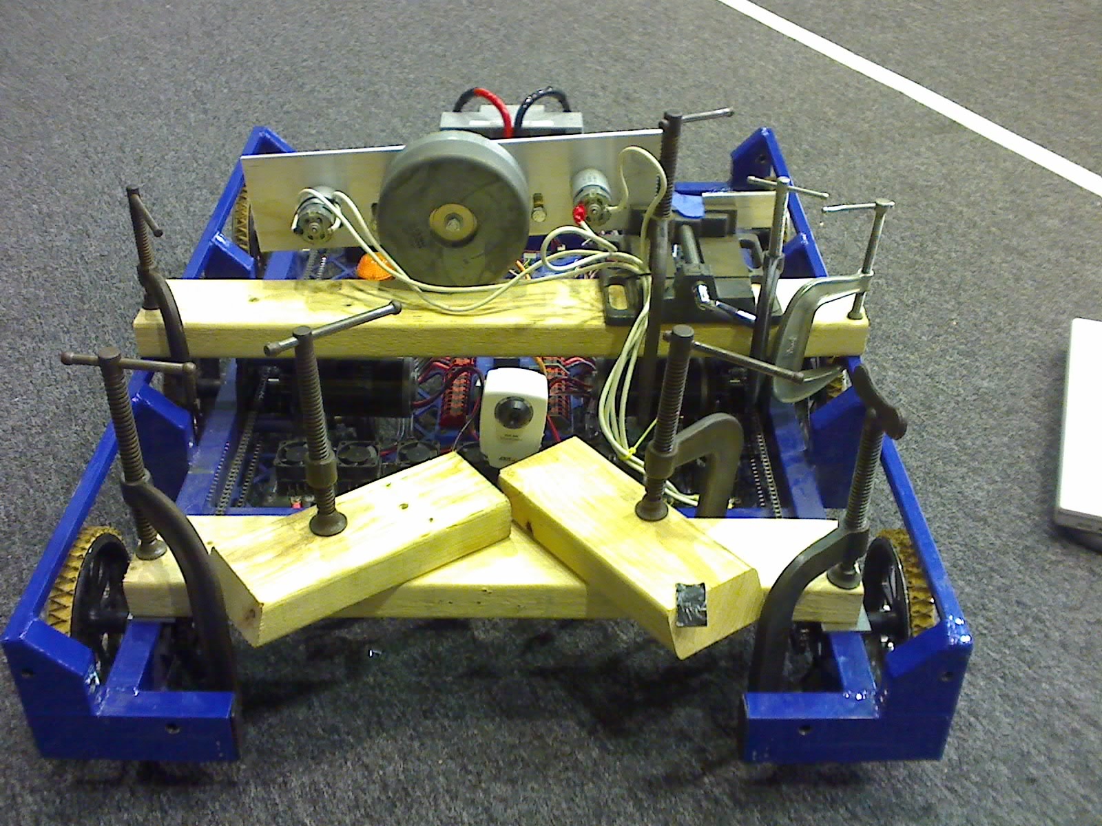
Today, we continued prototyping dual roller systems. We worked hard to emulate the drawings we had, but still found minimal success with the belt-driven systems. The faster the rollers were moving, the better the results. However, if the rollers were moving too fast, the window motors would stall and be damaged.
At the end of the evening, we strapped a Dewalt 3 Speed Drill onto the robot. With the shifter on middle or high speed and the clutch set very low, we were able to obtain and hold the ball extremely well. Videos of this system at work are below.
(There was a video here that has sadly been lost in the archives.)
(There was a video here that has sadly been lost in the archives.)


General Update
We continued to revise the two horizontal-rollers prototype so that it would be ready for proper implementation on the final design. Some of the most recent changes made include a stop, so that the ball is physically limited from entering more than 3 inches into our robot. Unfortunately in the earlier tests the ball actually entered 4 inches into our robot and roughly 1/16 inch off the ground. We also shifted the upper roller as forward as possible while retaining space for the bearing and moved the lower roller forward. The roller speed was also increased from the window motors with a 4 to 1 pulley reduction Videos should follow tommorrow after the design is perfected further.

Down in the shop we continued to pocket gears on the CNC and several sets for both the drive-train gearbox and the shooter winch gearbox have been manufactured already. Hopefully by the end of tommorrow we will be for the most part done pocketing the gears (at least the ones finalized on the design). They will be ready for ship by Monday or Tuesday.
Prototyping Progress
Dual horizontal rollers with tennis racquet grip tape = money.
Team 254 finally finished the initial prototype for dual horizontal rollers this evening (Based on 148’s prototype) and after much tweaking we found that the rollers held the ball securely and within the limits of the rules. The mechanism uses two small window motors running continuously (at least in this prototype), and it has little difficulty with picking up a ball on the go. For a final design, the rollers should spin faster to ensure that the ball is picked up 100% of the time, and actual placement of the rollers will need to be tweaked to perfection.

(There was a video here that has sadly been lost in the archives.)
(There was a video here that has sadly been lost in the archives.)
On the third day…
After calling many fabrication shops in Southern California within a radius of 45 miles, we ended up at the California Polytechnic University, Pomona shop. Our metal forming division was lucky enough to find the proper die to create the 45 degree bends on a 100 ton press brake. Setting up the machinery and completing the bends took 6 hours.
Our newly acquired sponsor, TOMCO Products in Azusa, was able to perform the 90 degree bends with a very quick turn around.
Below are our newly trained press brake operators holding the first bent plate

Here’s one of our highly skilled operators hard at work(or hardly working)

Here’s a plate being formed

Here’s another photo of a plate being formed

Here’s our assembly and inspection division test fitting the formed pieces

Here’s where Jesus joins metal with all his might

Oh, for your enjoyment
(There was a video here that has sadly been lost in the archives.)
Oh, and uhh.. here’s the current status of the parts:
We currently have one fully welded base, two tacked bases, and one base waiting to be welded.
Jesus needs to take a break, so, he’ll be back on Friday to complete joining metal.
Finally, below is an artist depiction of our team’s weekly activities courtesy of our comic division:

The work of Jesus
Today, the battery boxes and superstructure sides were welded. We’re attempting to bend the base plates before we go ahead and begin to weld the drive base.
In the meanwhile, here’s some photos of Jesus and his special touch.
Jesus welding a battery box

The completed welds on the superstructure sides

Here’s another shot of the superstructure sides

Here’s the battery box plates before they’re welded.

Attempting to center the battery connector tabs

Here’s the jig that we used

Here are two almost-complete battery boxes(tack welds need to be filled in)

In the hands of Jesus
The events portrayed in this post are from 10:30 PM to 6:47 PM. Events occur in real time. (Que 24 music)
10:30 PM: Kiet and Richard leave West Covina to meet Kirk in Kettleman, CA.
1:40 AM: Goods are exchanged (as pictured)
Loading the goods to the Prius

All the goods are accounted for
8:00 AM: Arrive at Ride and Show with robot parts. Assemble the superstructure sides and Jesus tack welds all 8 pieces.
Three superstructure sides that were just tack welded

These superstructure sides cleaned up and ready to be welded


Jesus welding a superstructure piece


3:00PM: Shafts are picked up from Pacific Precision
3:30PM: Jesus welds 4 superstructure sides and the other 4 are ready for tomorrow morning.
Four fully welded superstructure sides

Four fully welded superstructure sides and the other four are ready to be welded

3:40 PM: Picked material to make the back tube for the robot chassis and will be machined later today.
4:00 PM: Shafts from Pacific Precision are picked up.
5:20 PM: Battery Box Side Plates are finished and prepped for welding tomorrow.
Battery Box Side Plates

5:40 PM: The Battery Tabs are prepped to be drilled and tapped at Ride & Show tomorrow
Battery Tabs Queued For Machining

6:47 PM: Shafts are packaged and shipped to 254
Kiet will be escorting the box to shipment location

Zero to Robot Parts in 6 Hours (or so)
All of the robot chassis and super structure parts were completed today and are on their way to West Covina to be welded and then powercoated. The front plugs will be machined tomorrow and will be mailed down to arrive on Tuesday at the same time that the base plates that Mike D from team 233 made for us.
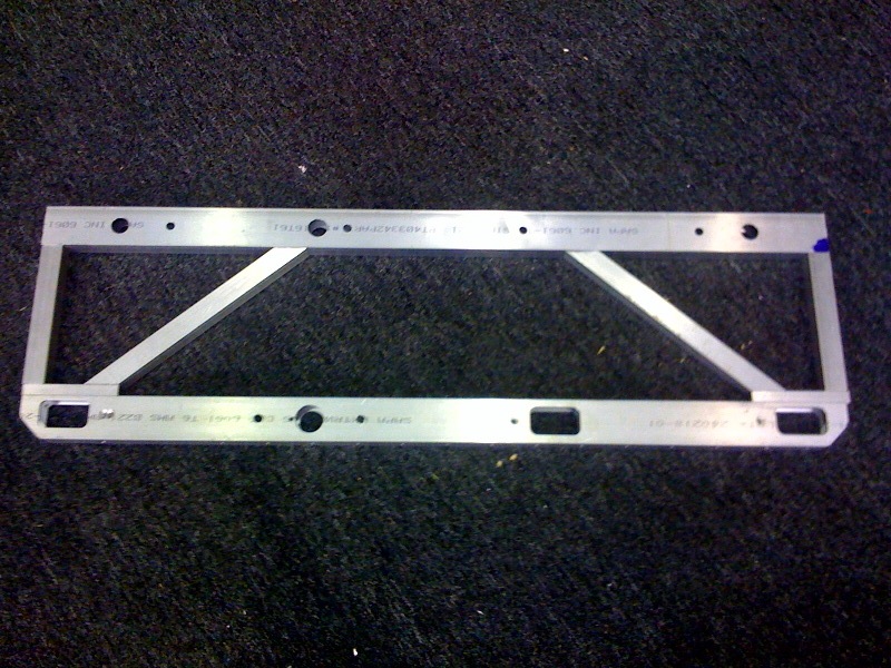
Here is a picture of the 12 different sets of pieces that are on their way down.

Here is a picture of the pieces set next to each other to give you an idea of what it will look like completed.

Additional Vertical Roller Testing
This was a test using dual 1/2″ rollers wrapped with duct tape. During the test, the rollers separated slightly after coming in contact with the ball once hitting the 3″ limit(simulates a spring loaded roller system).
(There was a video here that has sadly been lost in the archives.)
Lifting Arm Calculations
Review the PDF linked below for calculations for the lifting arm. If the PTO is driven on the low gear side (14 to 64), then an additional reduction of approximately 8:1 will be required to drive the arm. This is easily achievable in two stages. If the PTO is driven from the high gear side (30 to 48), then an additional reduction of about 23:1 is required – still achievable in two stages, but requires rather large and small sprockets. With 4 CIMS, the lift can occur in about 1/2 second. With only 2 CIMS, it could still work if geared properly (twice the reduction), but it would take twice as long.
The calculations below are presented in a fashion that should be understandable by the astute high-school student who has completed a Physics class.
Vertical Rollers Testing
During the previous two days, we attempted to design and prototype different roller orientations with minimal success. Before we were able to record a video of the horizontal roller setup, we determined that the setup held the ball well(going forward). While attempting to move the prototype backward, the ball would not stay in contact with the roller.
Oy. We determined that his was definately a problem. Horizontal roller utilizing a 1/2″ diameter round shaft will not meet our required specifications.
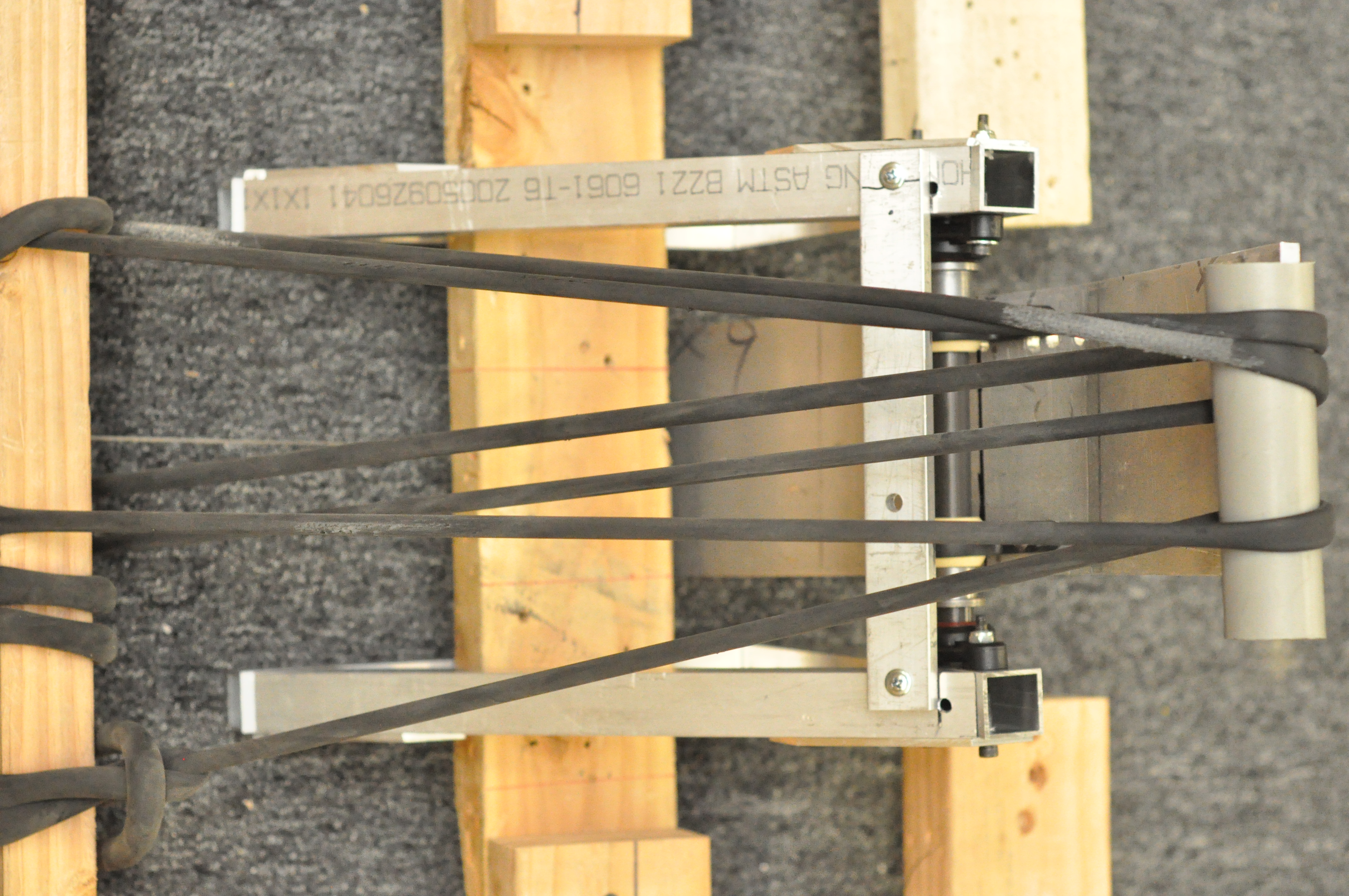
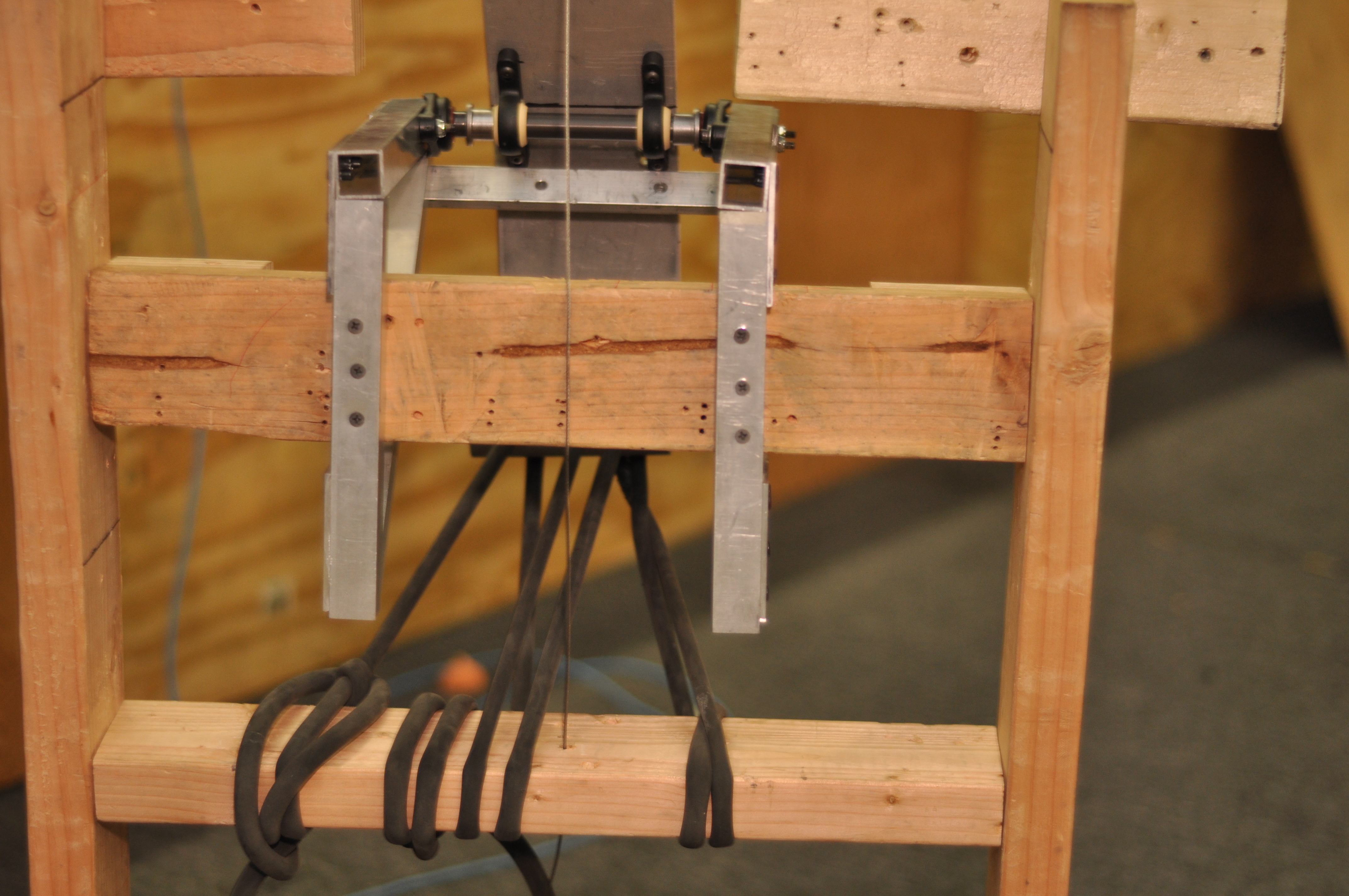
We moved onto an idea that our student design group envisioned… dual vertical rollers.
The vertical roller test(s) utilized the following parameters:
1. One roller spinning at half speed, one at full
2. One roller with rotational resistance, one roller at half speed(This test demonstrated the best results)
3. Both rollers spinning at full speed
We determined that the vertical roller setup requires that the ball is only pulled into the prototype under a specific set of conditions. (It doesn’t really work…..)
Please note that this is a proof of concept test.
(There was a video here that has sadly been lost in the archives.)
The artist depiction below displays the team hard at work on new prototypes.

Today’s Progress
Today we began to manufacture the robot frame. Currently the CNC is turning them out after a laborious 3 passes in order to bore all the holes. Hopefully we will have them done and ready to ship out by tomorrow afternoon.
We also furthered our progress on the vacuum prototype, unfortunately with little success. Increasing the size of the hose running to the suction cup did not yield any positive results. We should continue to explore the benefits of the vacuum as it seems the most promising ball-manipulation system.

Manufacturing and Prototyping Progress
MANUFACTURING
Today, construction on the tensioner cams was completed.
PROTOTYPING
Today we did extensive prototyping with vacuums. We continued to work with the two-stage impeller assembly hooked up to 2 fisher price motors. The impellers are currently running with a 1:1 reduction off of the fisher price motors. We hooked it up to a 4″ funnel which we mounted on the front of the 2009 drivebase.
The vaccum seems to work much better than any roller systems we have found. It maintains good suction on the ball. The only potential issue is getting the ball, which may be able to be solved with adequate driver practice.

(There was a video here that has sadly been lost in the archives.)
(There was a video here that has sadly been lost in the archives.)
(There was a video here that has sadly been lost in the archives.)
(There was a video here that has sadly been lost in the archives.)
Parts Out for Anodize
We dropped off the wheels, bearing housings, and gearbox spacers at the anodize shop today. Hopefully we should see them back in a few days.
Design, Manufacturing and Prototyping Progress
DESIGN
Today, the design team worked to finalize the drivetrain. The baseplate will be sent out to be cut by Mike D at NASA Kennedy’s waterjet shop first thing tomorrow morning.
MANUFACTURING
The CNC was running all day to cut all of the drivetrain tensioner cams. They will be clear anodized.
A large group of students scotch brited wheels so that they are ready to be delivered to the anodize shop. They will be delivered, along with the gearbox spacers and bearing housings, to the anodize shop tomorrow.

PROTOTYPING
Today, we continued to prototype Ball Retention Mechanisms. We tested several different types of rollers and shafts on the balls with mixed results. Several students and mentors also worked on modifying a 2 stage vaccum impeller to work with 2 FP motors. More testing will occur tomorrow
Also, we were a little worried that the robot with a thick baseplate underneath wouldn’t make it over the ramp. We decided to put a piece of polycarbonate on the bottom of the robot and test just to make sure. The robot went over the ramp just fine, as demonstrated in the videos below.
(There was a video here that has sadly been lost in the archives.)
(There was a video here that has sadly been lost in the archives.)
Manufacturing and Prototyping Progress
Today, Team 254 finished CNCing the wheel hubs for each team and cut the stock needed for the cams. In the meantime, the CAD team continued tweaking the baseplate design and other groups continued working on prototype methods of handling the soccer balls.
One of the more successful protoypes the team developed was an intake roller that gave the ball backspin, keeping it close to the robot while the robot moved. The prototype is still in development, and various rollers and traction materials are being tested.
Manufacturing Progress
After almost 18 hours of machining the last two days we completed the first operation on all 70 wheels. We began the second operation and now have 20 completed wheels. The rest should be completed in ~3.5 hours tomorrow. We also began making wheel and gearbox spacers.

Revised Launcher Assembly


Ball launching assembly launches ball out of the field when set at the high power position.
(There was a video here that has sadly been lost in the archives.)
Ball launcher assembly launches ball 44ft on the low power setting.
(There was a video here that has sadly been lost in the archives.)
Here’s the hit spread photo after a few test shots.

