
Day #23: Wiring and Prototyping
Wiring
Wiring the main robot chassis was continued today, as students and mentors mounted and wired 8 port solenoids. As well, the spike was wired and progress was made in the decision on how to mount the compressor. With majority of the base wiring complete, the team is currently waiting on new cRIO modules to arrive so that they can be mounted and wired as well.
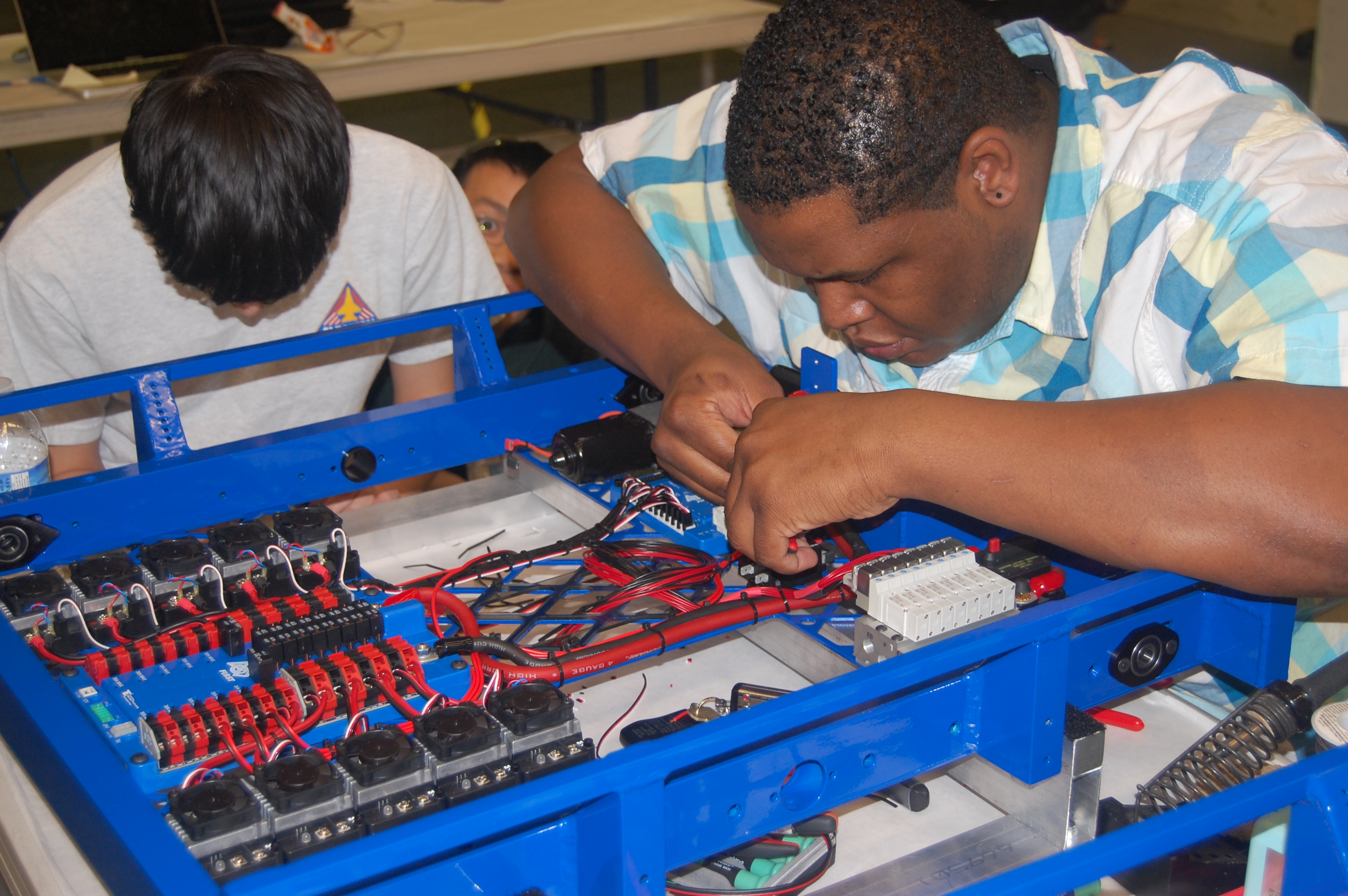
Wiring the solenoids
Prototyping
Prototyping was divided into multiple subgroups today, with students working on the loading mechanism, the conveyor, as well as mounting a mini CIM motor to power the intake prototype.
Loading Mechanism
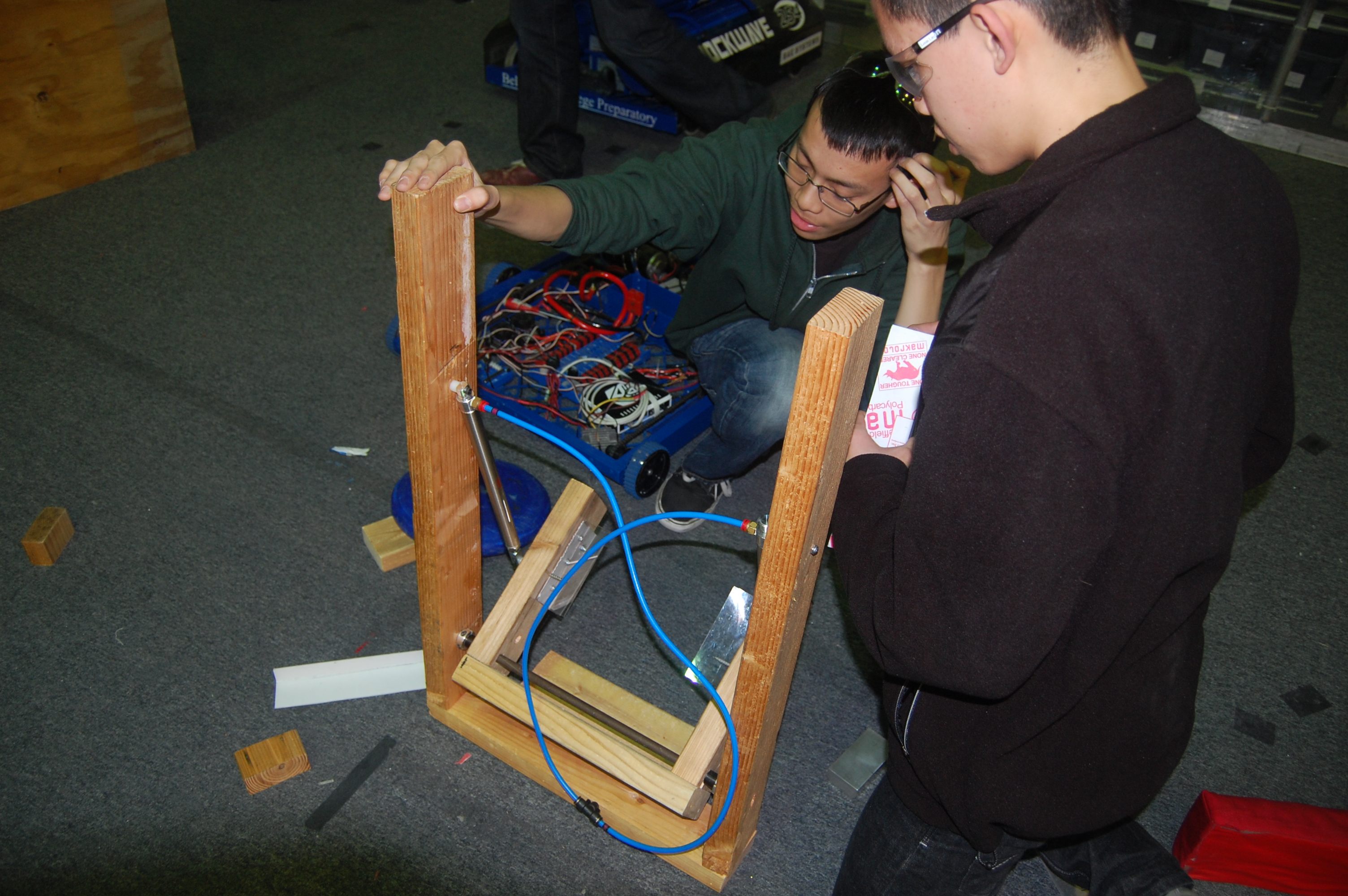
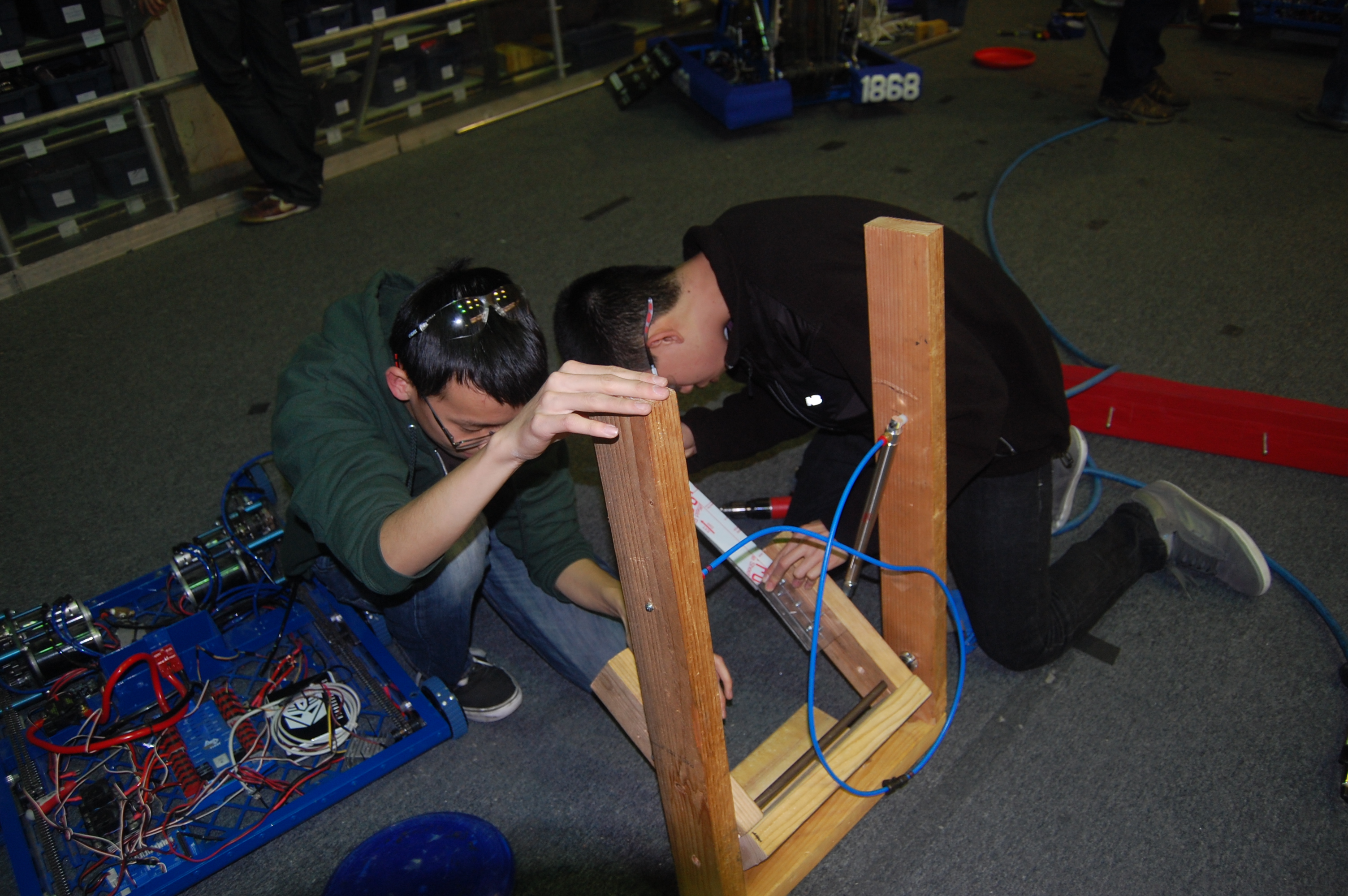
A select group of students decided to prototype the loading mechanism which transfers the frisbee from the conveyor to the shooter. Using polycarb, wood, and pistons, they were able to manufacture a working prototype to serve as a successful proof-of-concept reinforcing designs already implemented into CAD.
Conveyor
Students worked to make a conveyor out of wood to use as a proof-of-concept with using 3/8″ hex shafts versus the previously favoured 1/2″. It is still a work in progress and is currently being assembled.
Intake
It was decided that to optimize the speed of rollers used in the intake, it is neccessary to modify the current intake design which had previously been powered solely by pneumatic drills to operate using a single mini CIM motor. To do so, students created 2 pulleys to direct power to the front rollers using polycord while the back rollers will be powered by gears at a 3:1 ratio. There was minor setbacks in the broaching of a 1/2″ gear, and as such the project was slowed. The modifications are still currently underway and will be documented in depth once they are completed.
Last night the intake prototype was modified to have both rollers powered by a mini-CIM, as shown in the photos below. The gears mentione above were used to power the bottom roller. This resulted in a theoretical max surface speed of 9.8 ft/s. When the frisbees were put through, there was virtually no observed speed reduction in the CIM due to the load. Because of this, it is alright to gear the intake for 18 ft/s theoretical surface speed, so this design will be proceeded with.
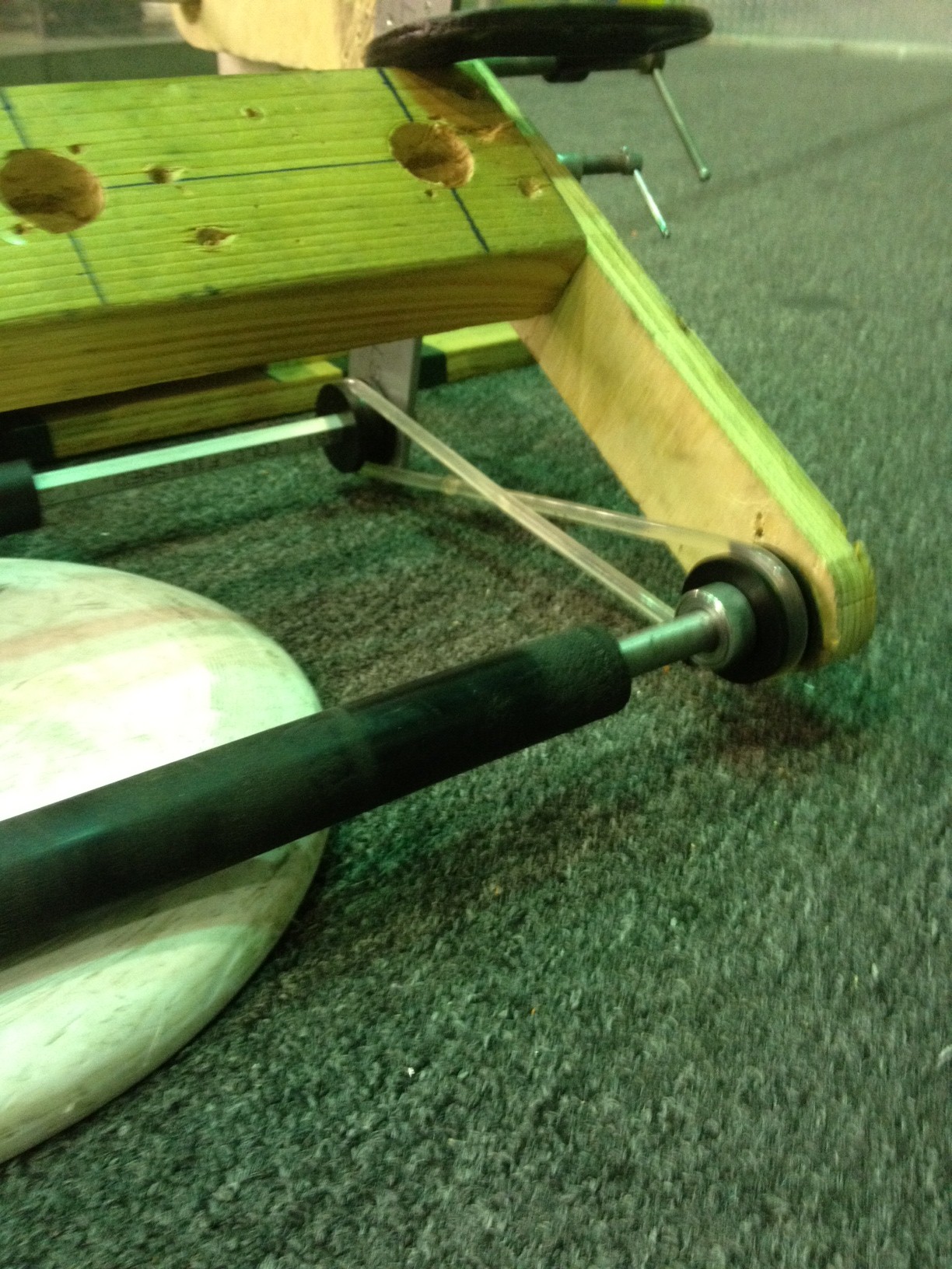
The front intake roller, connected with polycord
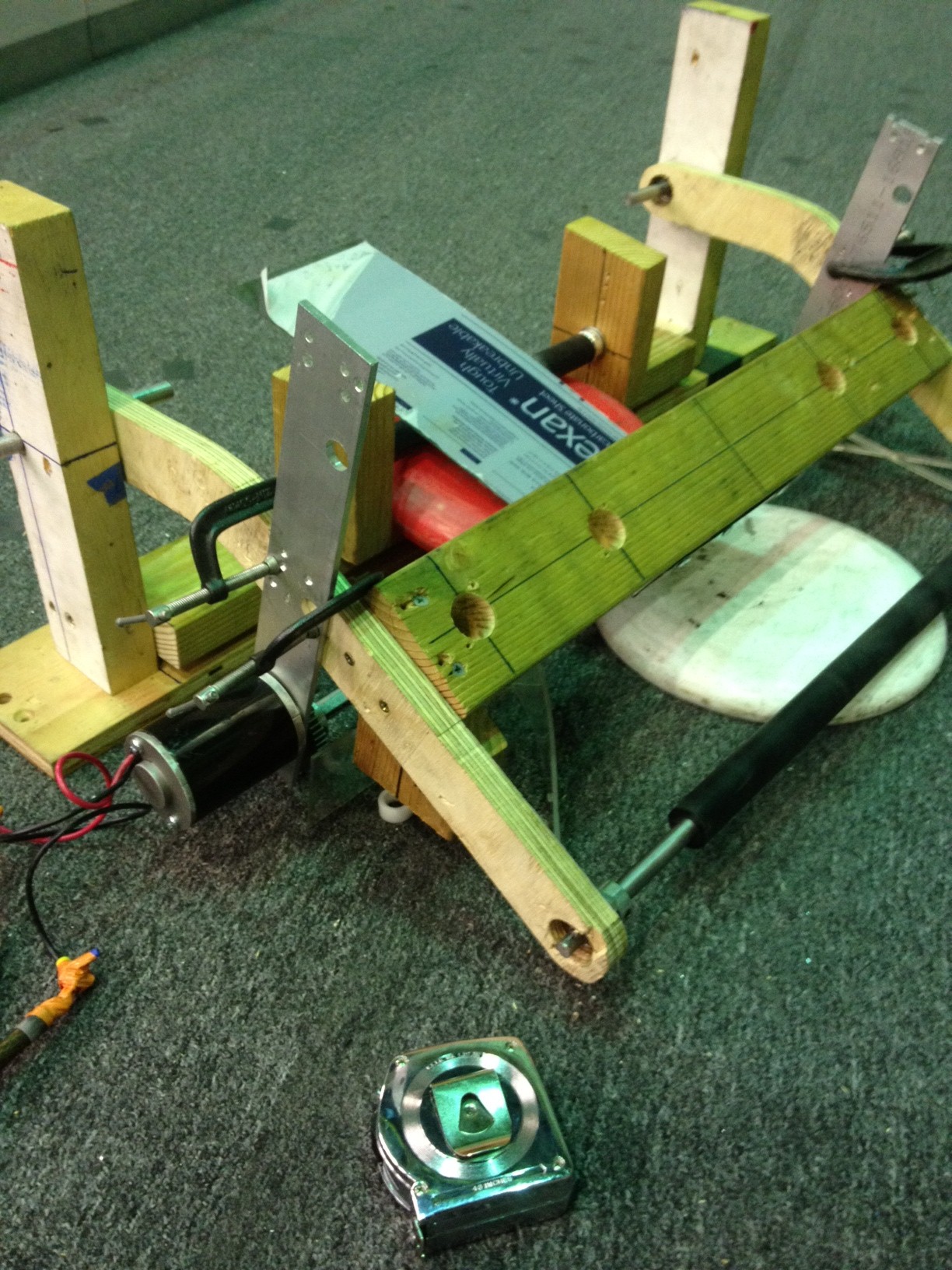
Both rollers powered by a mini-CIM
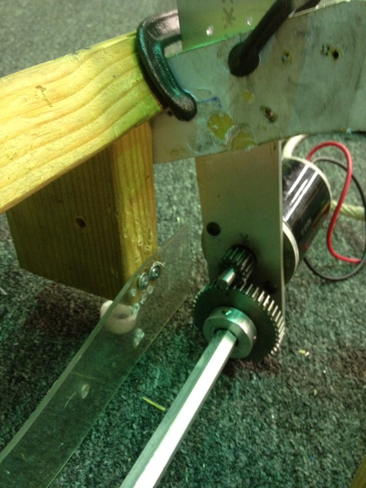
Bottom roller, with 3:1 reduction
Brogramming
The programmers continued graphing the 2012 robot’s shooter wheel RPM versus time. They experimented with both the bang-bang controller and a PID controller, as well as with and without a moving average filter. When using the bang-bang controller to control the shooter wheel, students found that using a moving average filter to filter the motor outputs produced smoother and more consistent results. The programmers spent a lot of time adjusting the P, I, and D terms of the PID controller. Though the PID controller’s graphs are relatively more stable and smoother than the graphs of the bang-bang controller, the PID controller either tends to overshoot its goal or to not reach it at all (mostly at 3500 rpm).
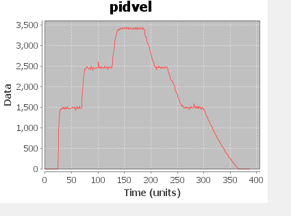
Graph of a PID-controlled shooter wheel (P = 0.007, I = 0.0, D = 0.003)
Action Items
- Get a quote on wood for bumper assembly
- Buy wood/cordura for bumper assembly
- Finish design changes on conveyor and intake assemblies
- Finish prototyping conveyor
- Start designing control board
- Start manufacturing bumper components
- Hook up a speed controller to the intake to figure out the minimum required torque.
- Measure the current draw with the ammeter.
