Blog - 2010
Lifting Arm Calculations
Review the PDF linked below for calculations for the lifting arm. If the PTO is driven on the low gear side (14 to 64), then an additional reduction of approximately 8:1 will be required to drive the arm. This is easily achievable in two stages. If the PTO is driven from the high gear side (30 to 48), then an additional reduction of about 23:1 is required – still achievable in two stages, but requires rather large and small sprockets. With 4 CIMS, the lift can occur in about 1/2 second. With only 2 CIMS, it could still work if geared properly (twice the reduction), but it would take twice as long.
The calculations below are presented in a fashion that should be understandable by the astute high-school student who has completed a Physics class.
Vertical Rollers Testing
During the previous two days, we attempted to design and prototype different roller orientations with minimal success. Before we were able to record a video of the horizontal roller setup, we determined that the setup held the ball well(going forward). While attempting to move the prototype backward, the ball would not stay in contact with the roller.
Oy. We determined that his was definately a problem. Horizontal roller utilizing a 1/2″ diameter round shaft will not meet our required specifications.
We moved onto an idea that our student design group envisioned… dual vertical rollers.
The vertical roller test(s) utilized the following parameters:
1. One roller spinning at half speed, one at full
2. One roller with rotational resistance, one roller at half speed(This test demonstrated the best results)
3. Both rollers spinning at full speed
We determined that the vertical roller setup requires that the ball is only pulled into the prototype under a specific set of conditions. (It doesn’t really work…..)
Please note that this is a proof of concept test.
Original video unavailable.
The artist depiction below displays the team hard at work on new prototypes.

Today’s Progress
Today we began to manufacture the robot frame. Currently the CNC is turning them out after a laborious 3 passes in order to bore all the holes. Hopefully we will have them done and ready to ship out by tomorrow afternoon.
We also furthered our progress on the vacuum prototype, unfortunately with little success. Increasing the size of the hose running to the suction cup did not yield any positive results. We should continue to explore the benefits of the vacuum as it seems the most promising ball-manipulation system.

Manufacturing and Prototyping Progress
MANUFACTURING
Today, construction on the tensioner cams was completed.
PROTOTYPING
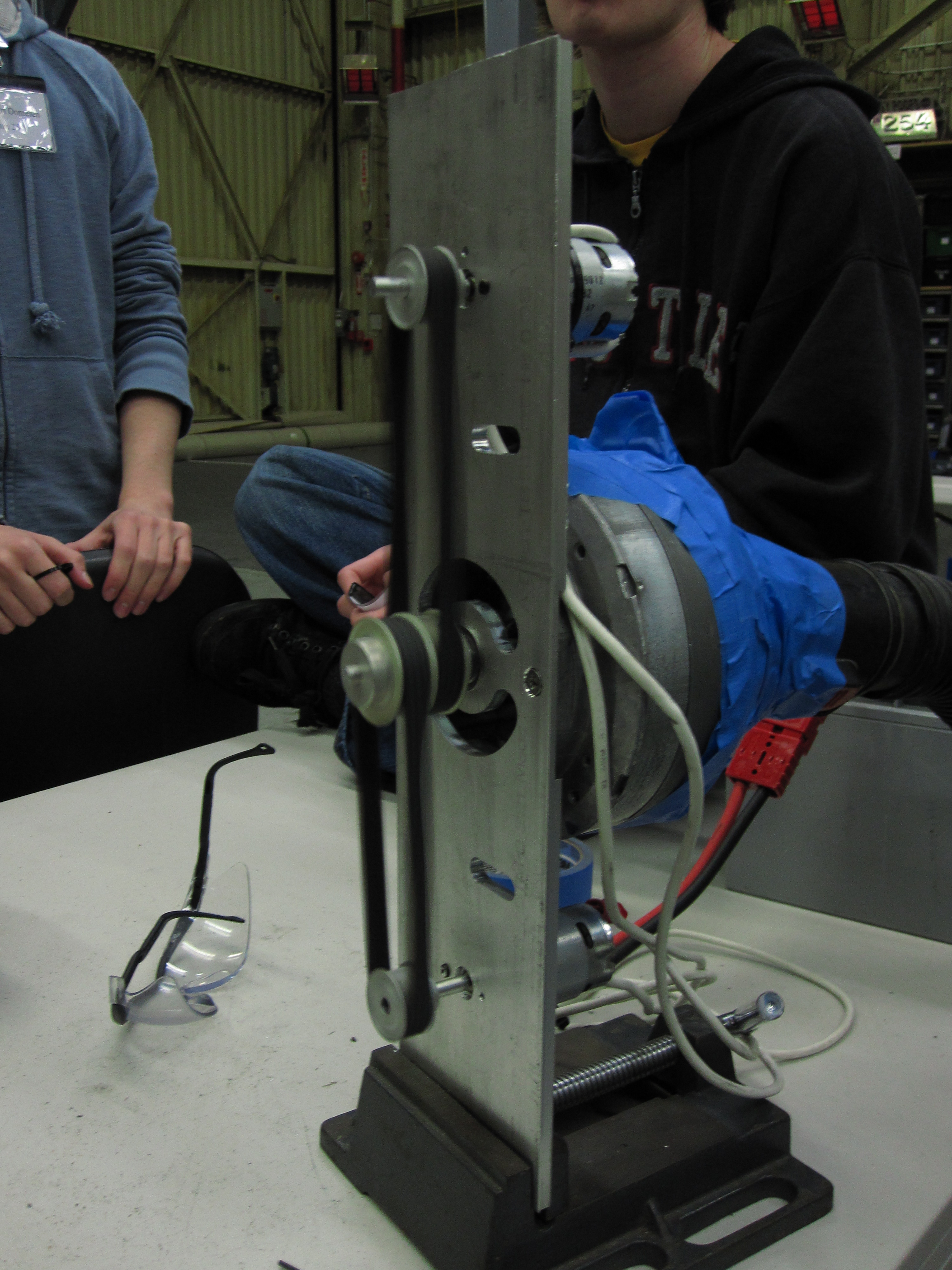
Today we did extensive prototyping with vacuums. We continued to work with the two-stage impeller assembly hooked up to 2 fisher price motors. The impellers are currently running with a 1:1 reduction off of the fisher price motors. We hooked it up to a 4″ funnel which we mounted on the front of the 2009 drivebase.
The vaccum seems to work much better than any roller systems we have found. It maintains good suction on the ball. The only potential issue is getting the ball, which may be able to be solved with adequate driver practice.
Original video unavailable.
Original video unavailable.
Original video unavailable.
Original video unavailable.
Parts Out for Anodize
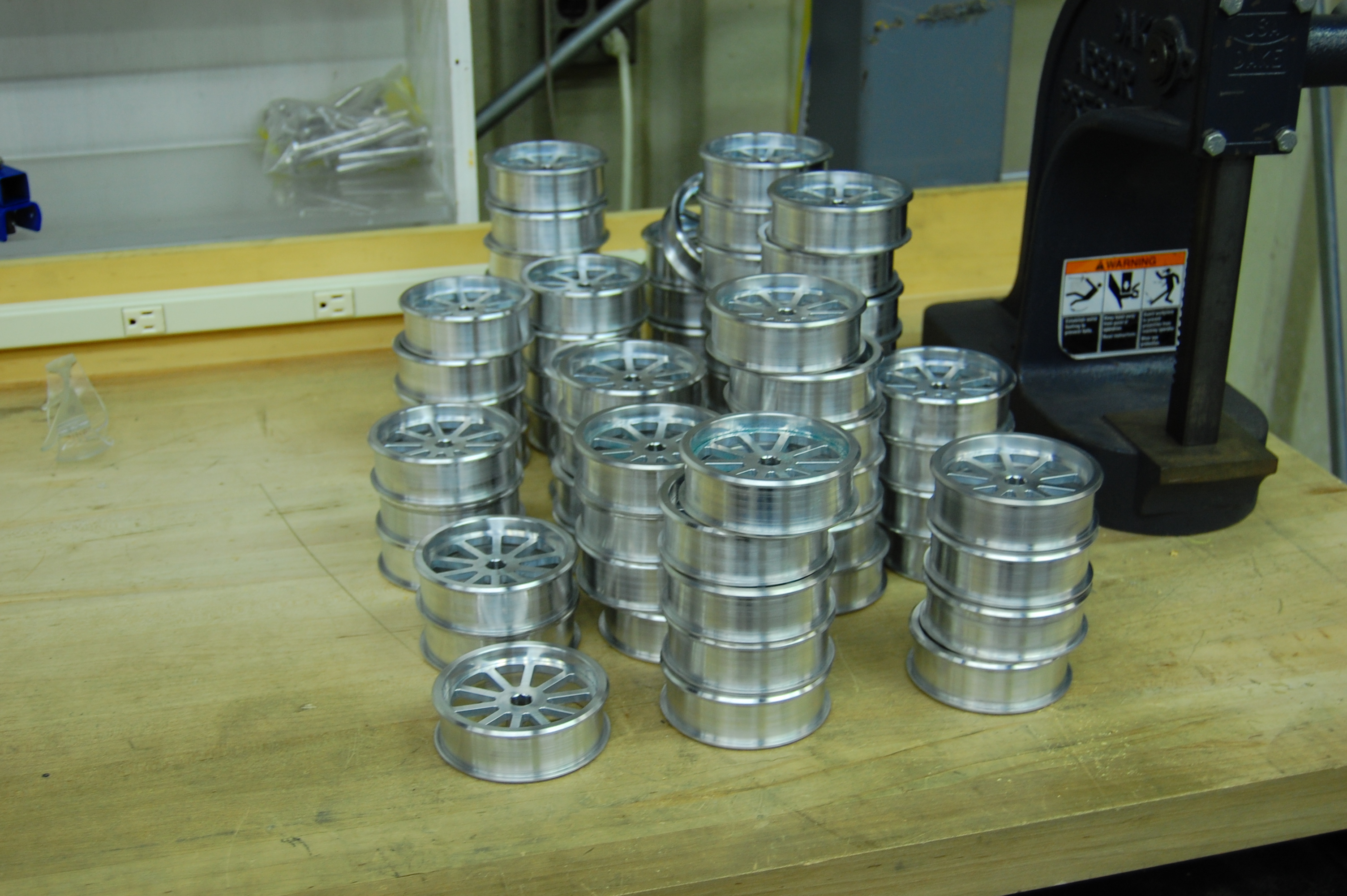
We dropped off the wheels, bearing housings, and gearbox spacers at the anodize shop today. Hopefully we should see them back in a few days.
Design, Manufacturing and Prototyping Progress
DESIGN
Today, the design team worked to finalize the drivetrain. The baseplate will be sent out to be cut by Mike D at NASA Kennedy’s waterjet shop first thing tomorrow morning.
MANUFACTURING
The CNC was running all day to cut all of the drivetrain tensioner cams. They will be clear anodized.
A large group of students scotch brited wheels so that they are ready to be delivered to the anodize shop. They will be delivered, along with the gearbox spacers and bearing housings, to the anodize shop tomorrow.
PROTOTYPING
Today, we continued to prototype Ball Retention Mechanisms. We tested several different types of rollers and shafts on the balls with mixed results. Several students and mentors also worked on modifying a 2 stage vaccum impeller to work with 2 FP motors. More testing will occur tomorrow
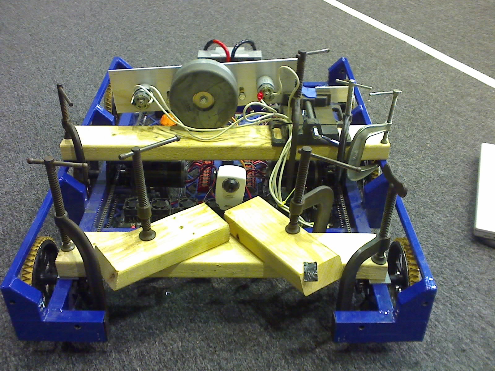
Also, we were a little worried that the robot with a thick baseplate underneath wouldn’t make it over the ramp. We decided to put a piece of polycarbonate on the bottom of the robot and test just to make sure. The robot went over the ramp just fine, as demonstrated in the videos below.
Original video unavailable.
Original video unavailable.
Manufacturing and Prototyping Progress
Today, Team 254 finished CNCing the wheel hubs for each team and cut the stock needed for the cams. In the meantime, the CAD team continued tweaking the baseplate design and other groups continued working on prototype methods of handling the soccer balls.
One of the more successful protoypes the team developed was an intake roller that gave the ball backspin, keeping it close to the robot while the robot moved. The prototype is still in development, and various rollers and traction materials are being tested.
Manufacturing Progress
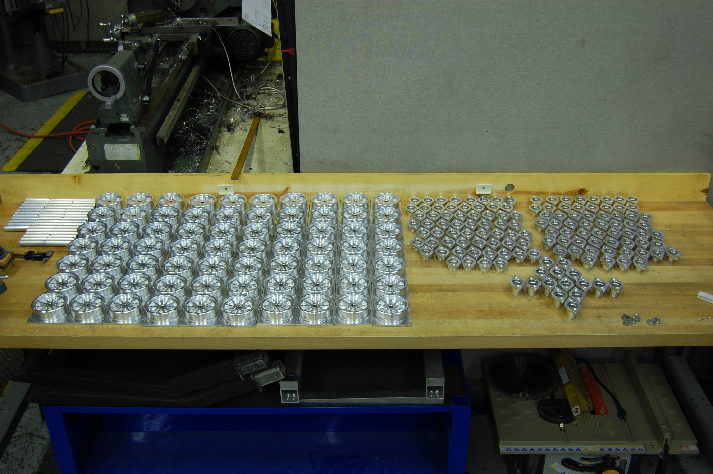
After almost 18 hours of machining the last two days we completed the first operation on all 70 wheels. We began the second operation and now have 20 completed wheels. The rest should be completed in ~3.5 hours tomorrow. We also began making wheel and gearbox spacers.
Revised Launcher Assembly
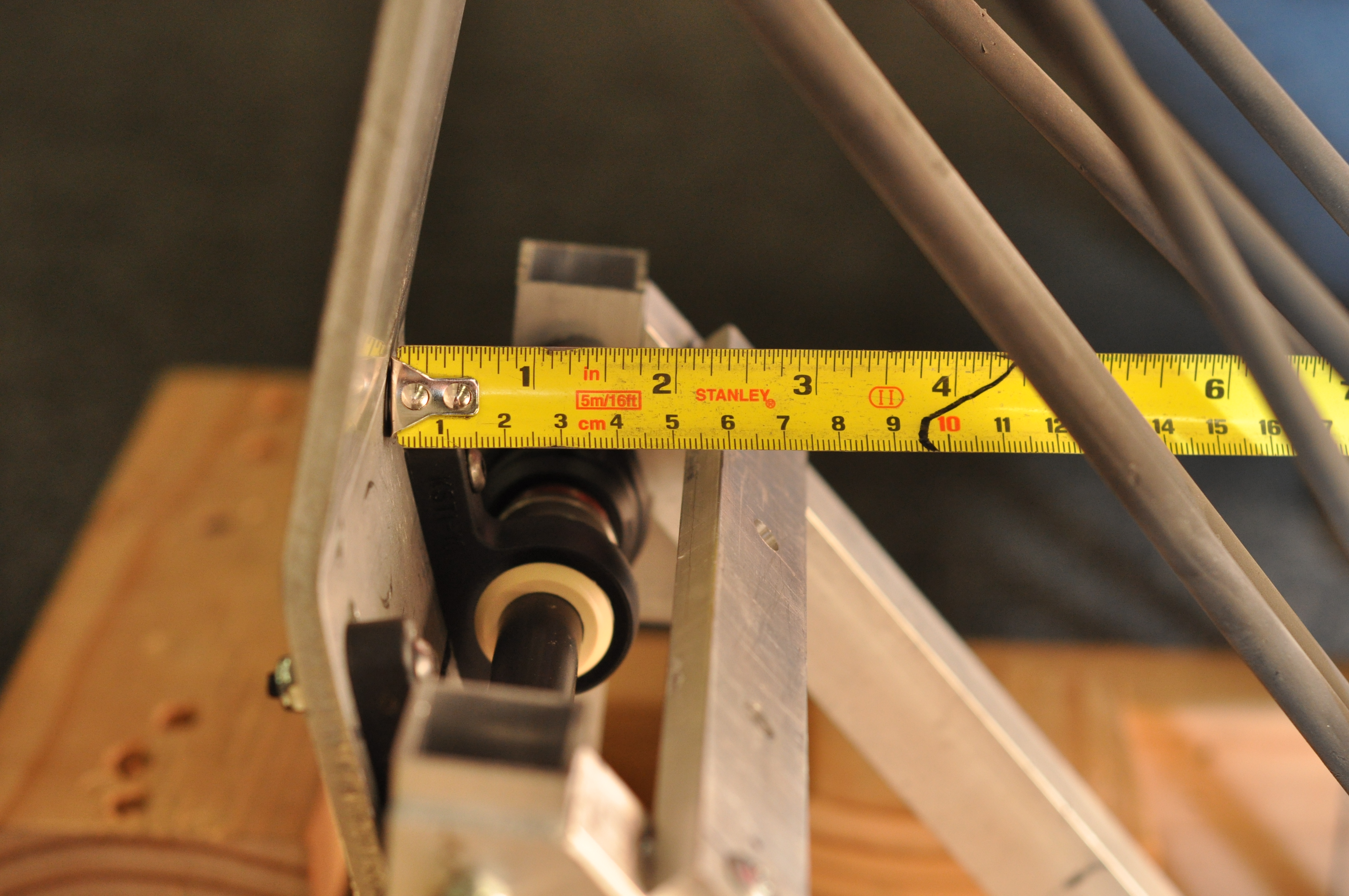
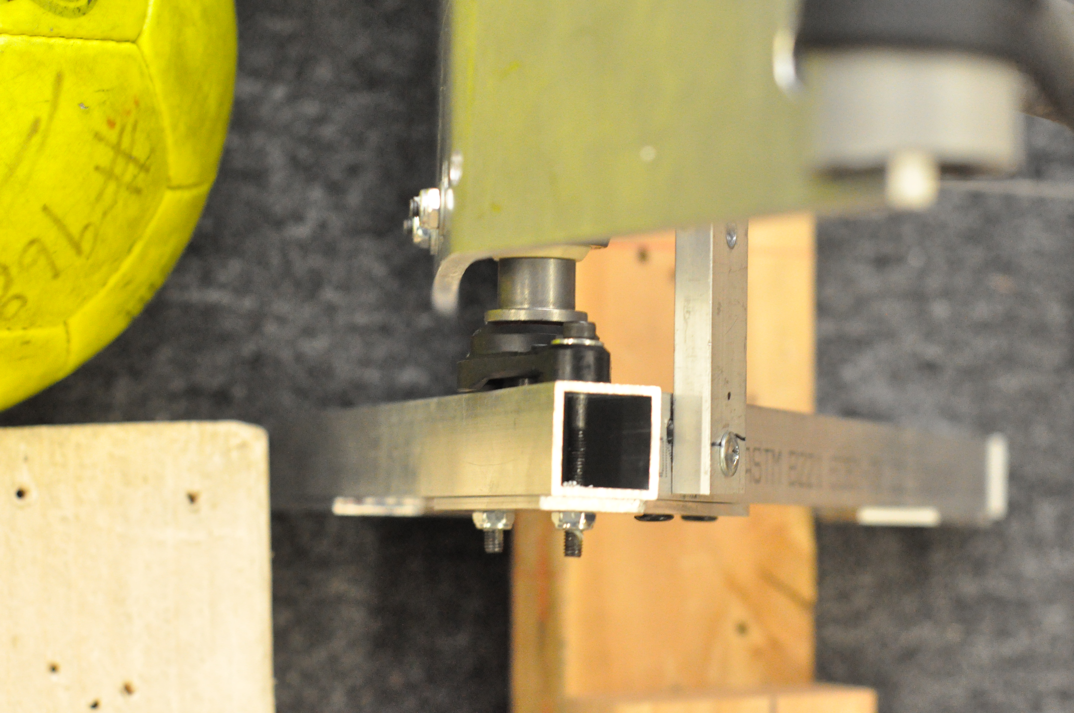
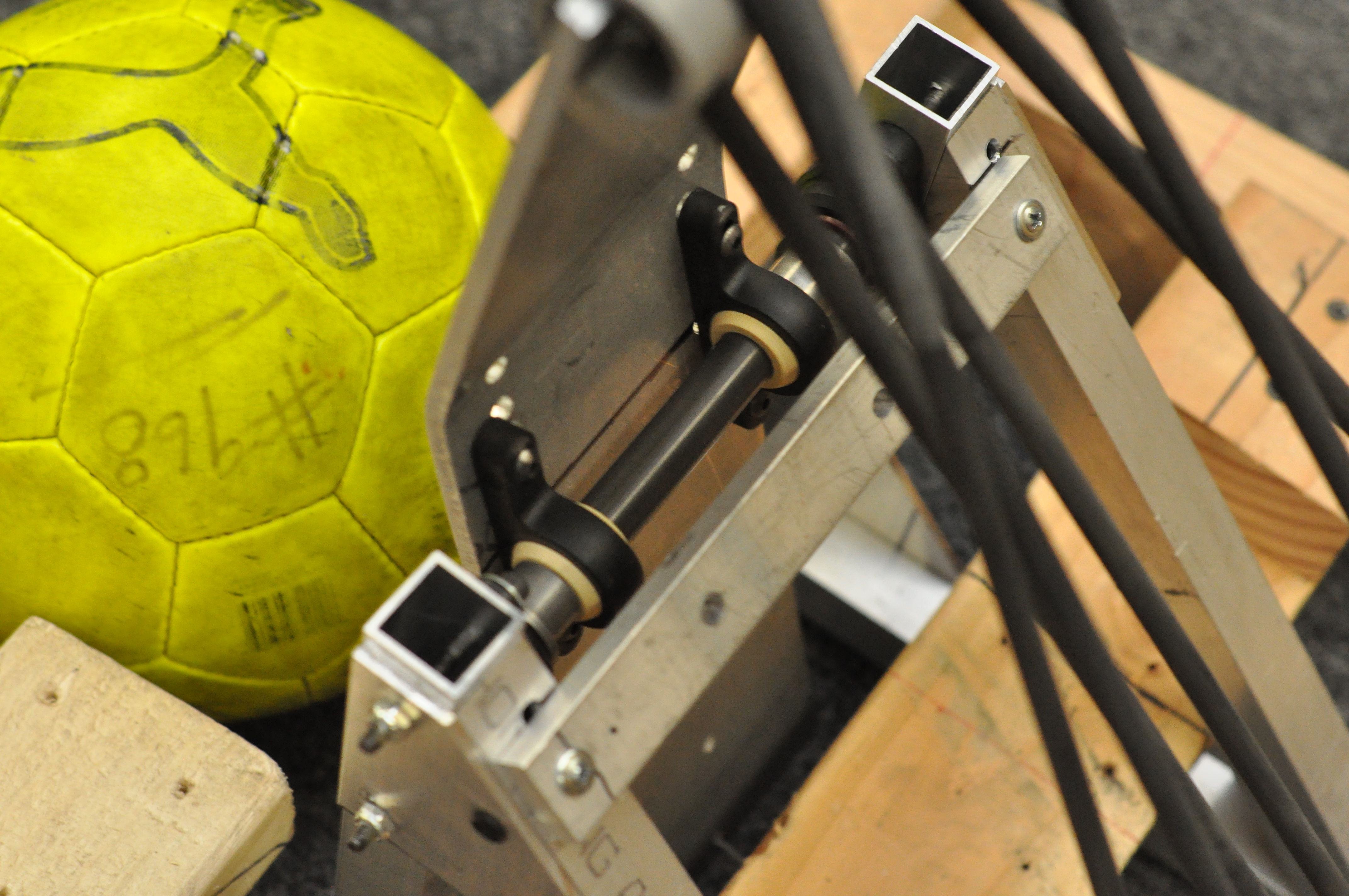
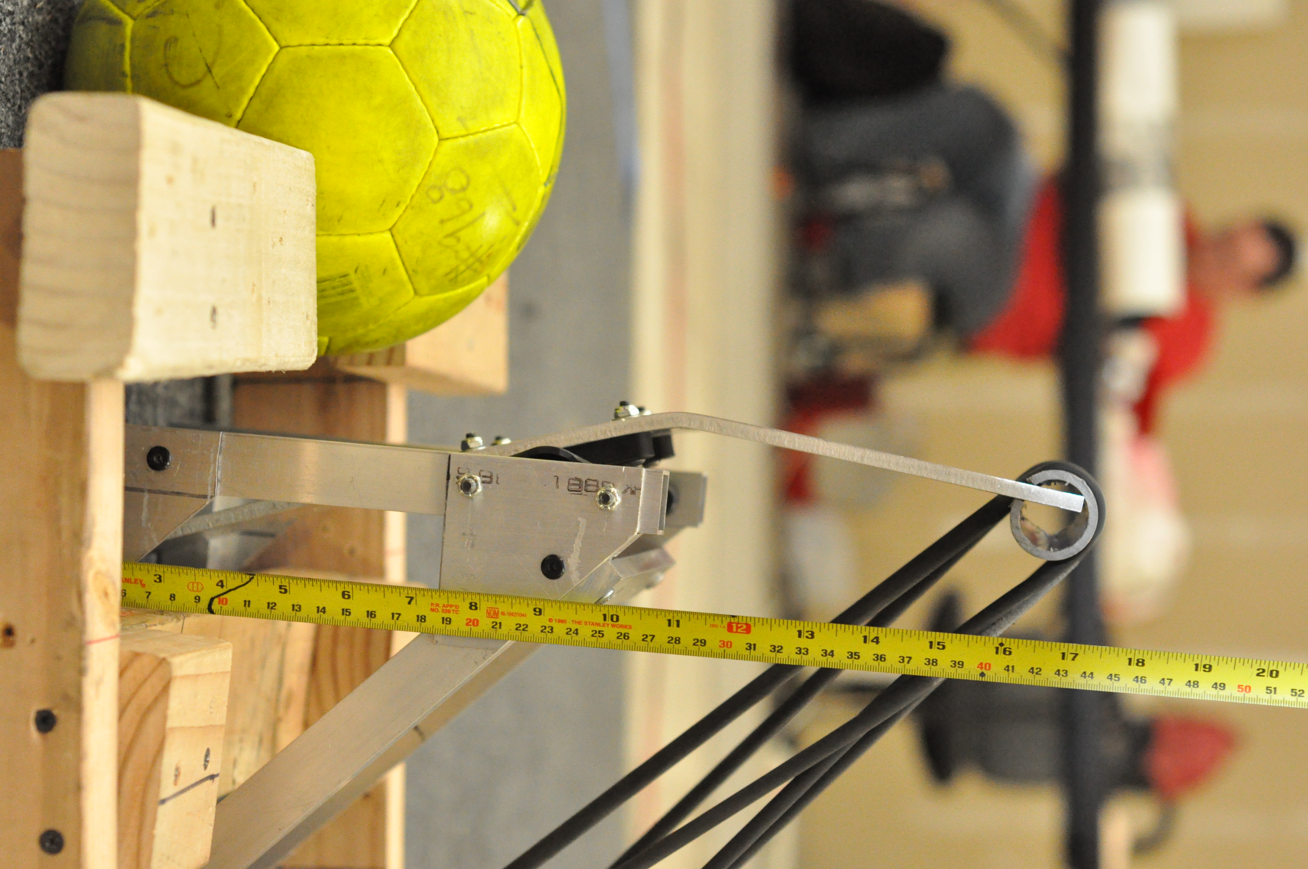
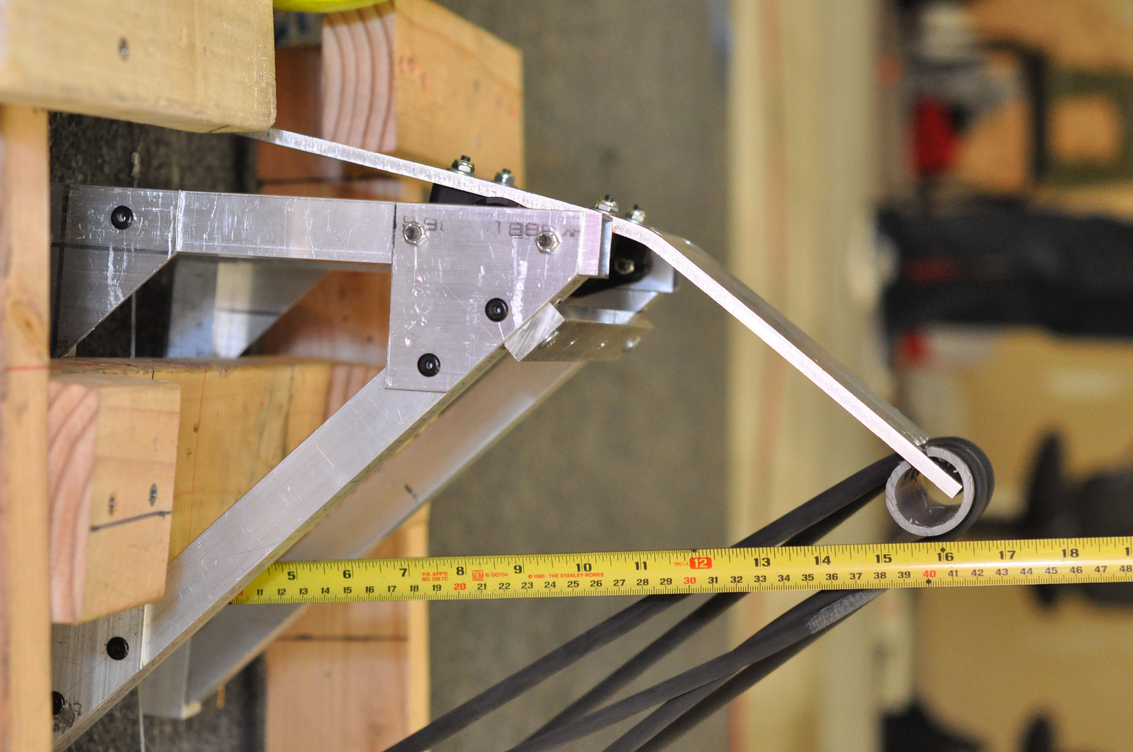
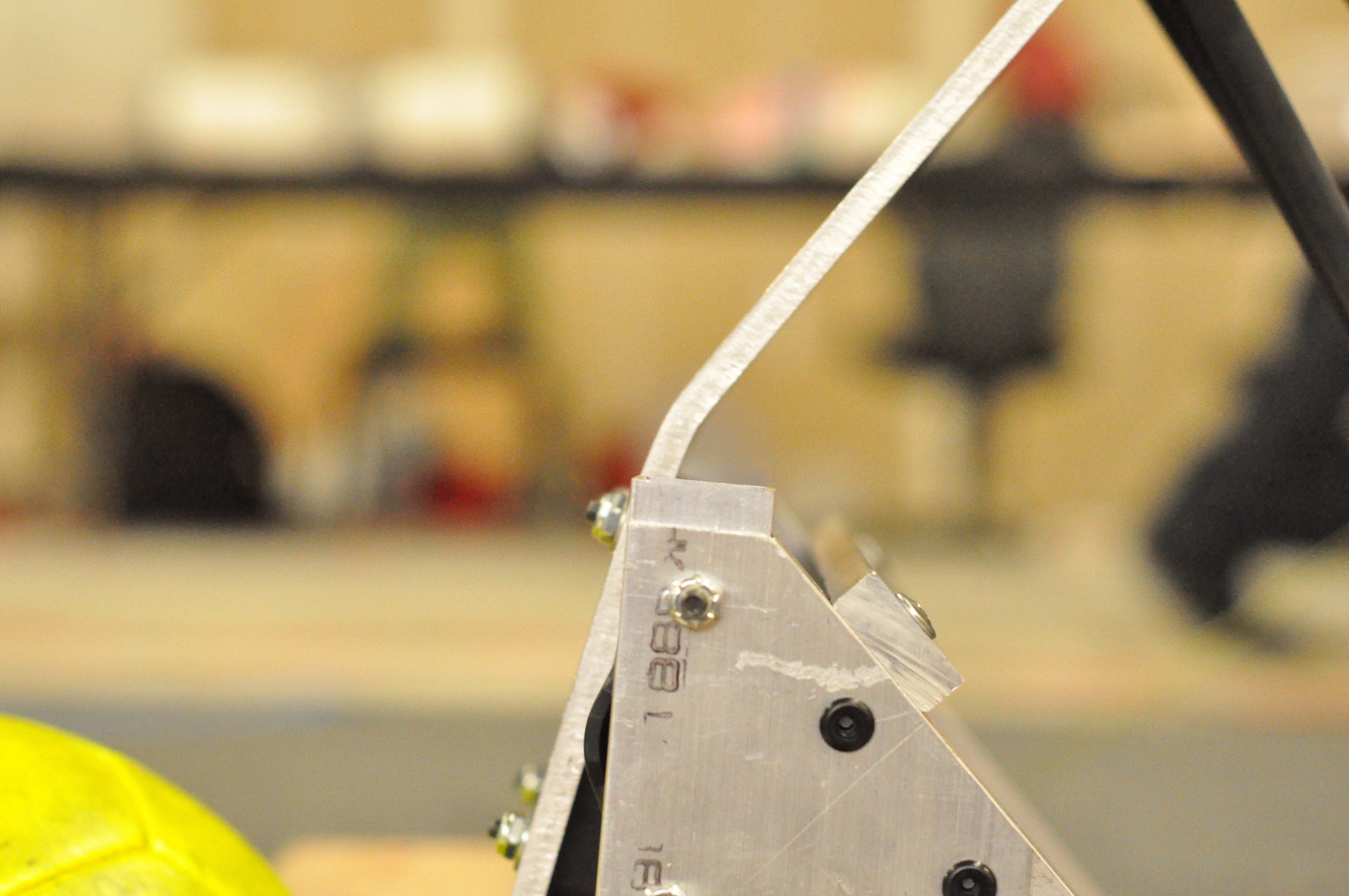
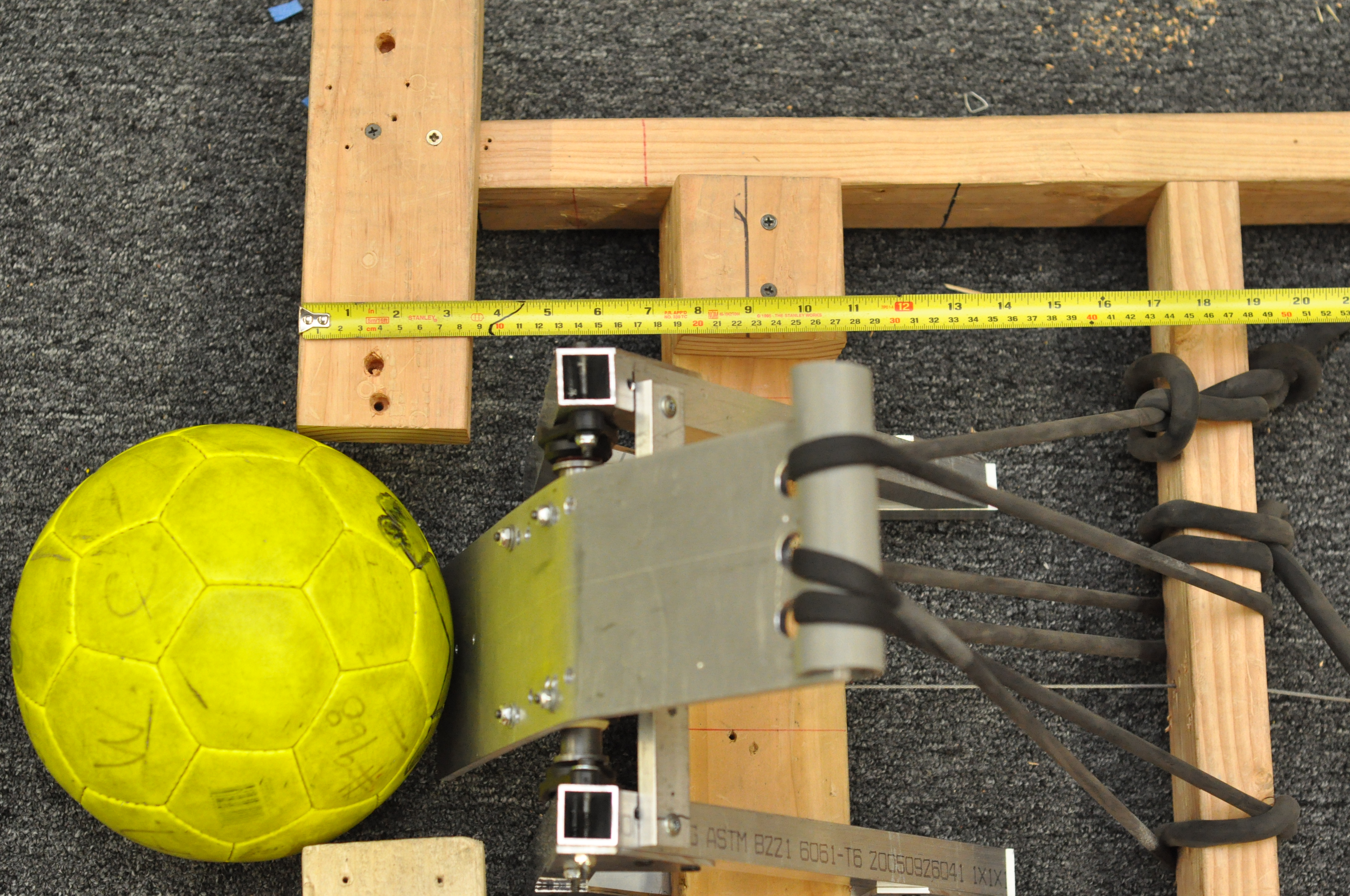
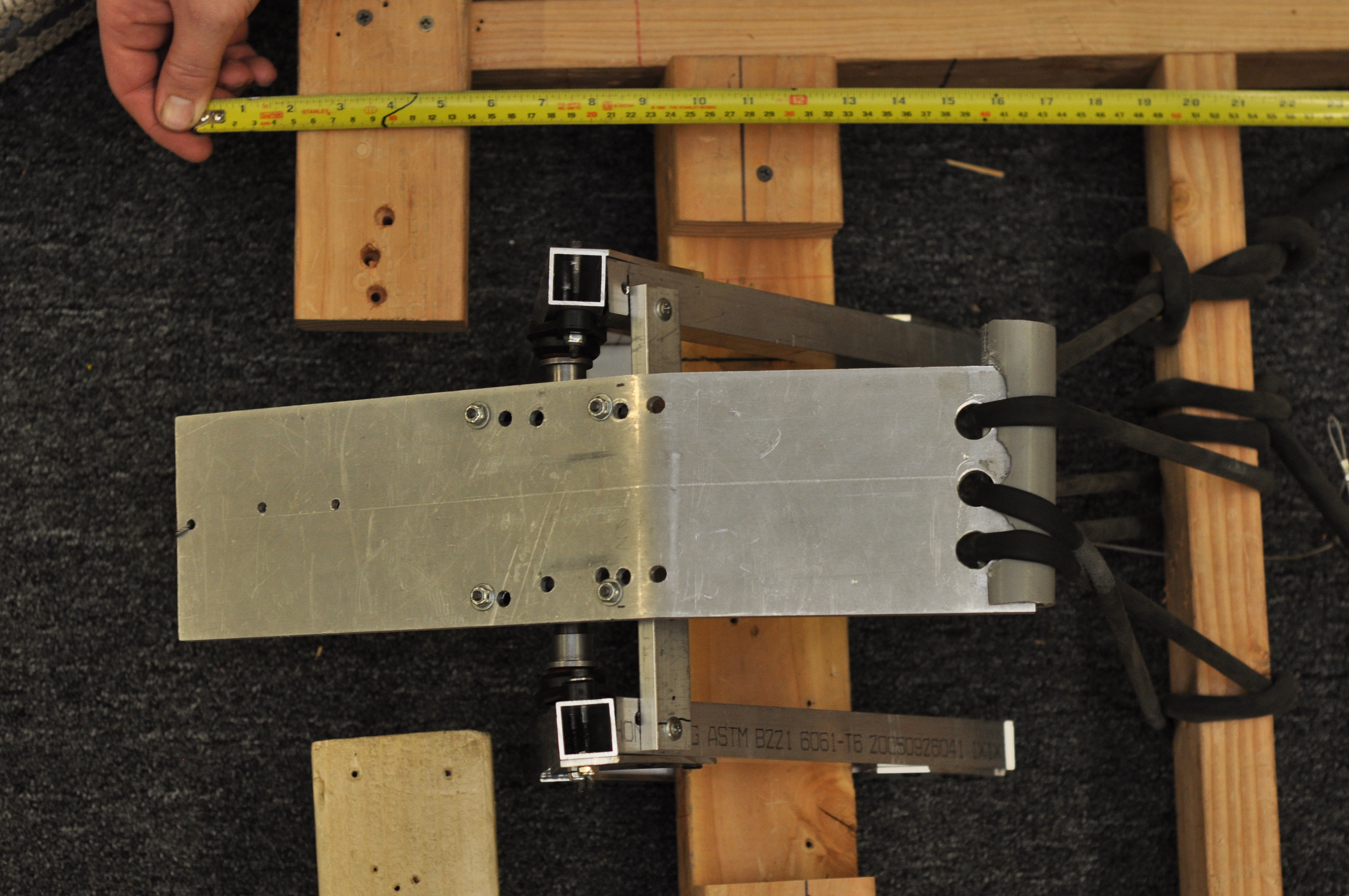
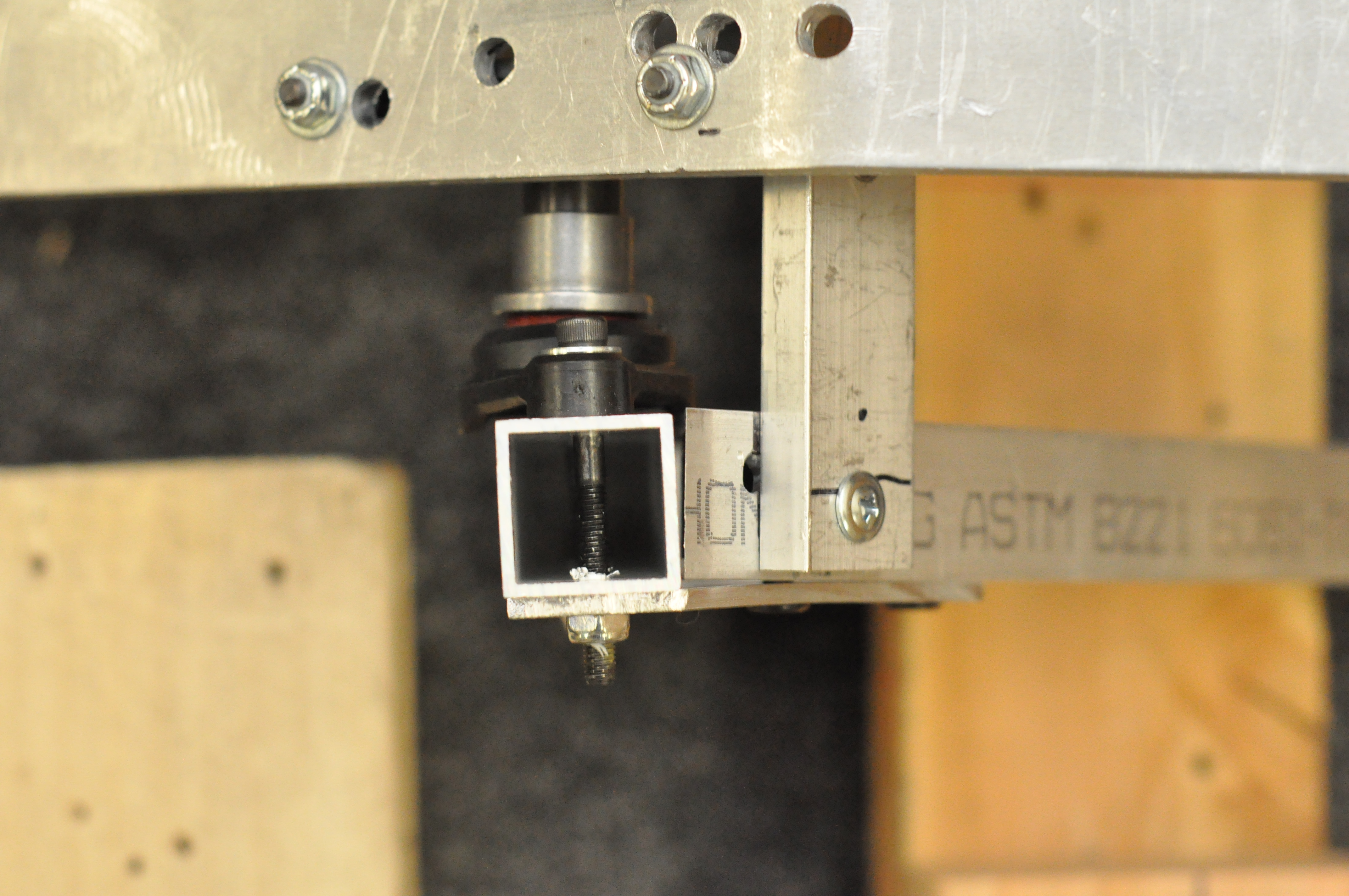

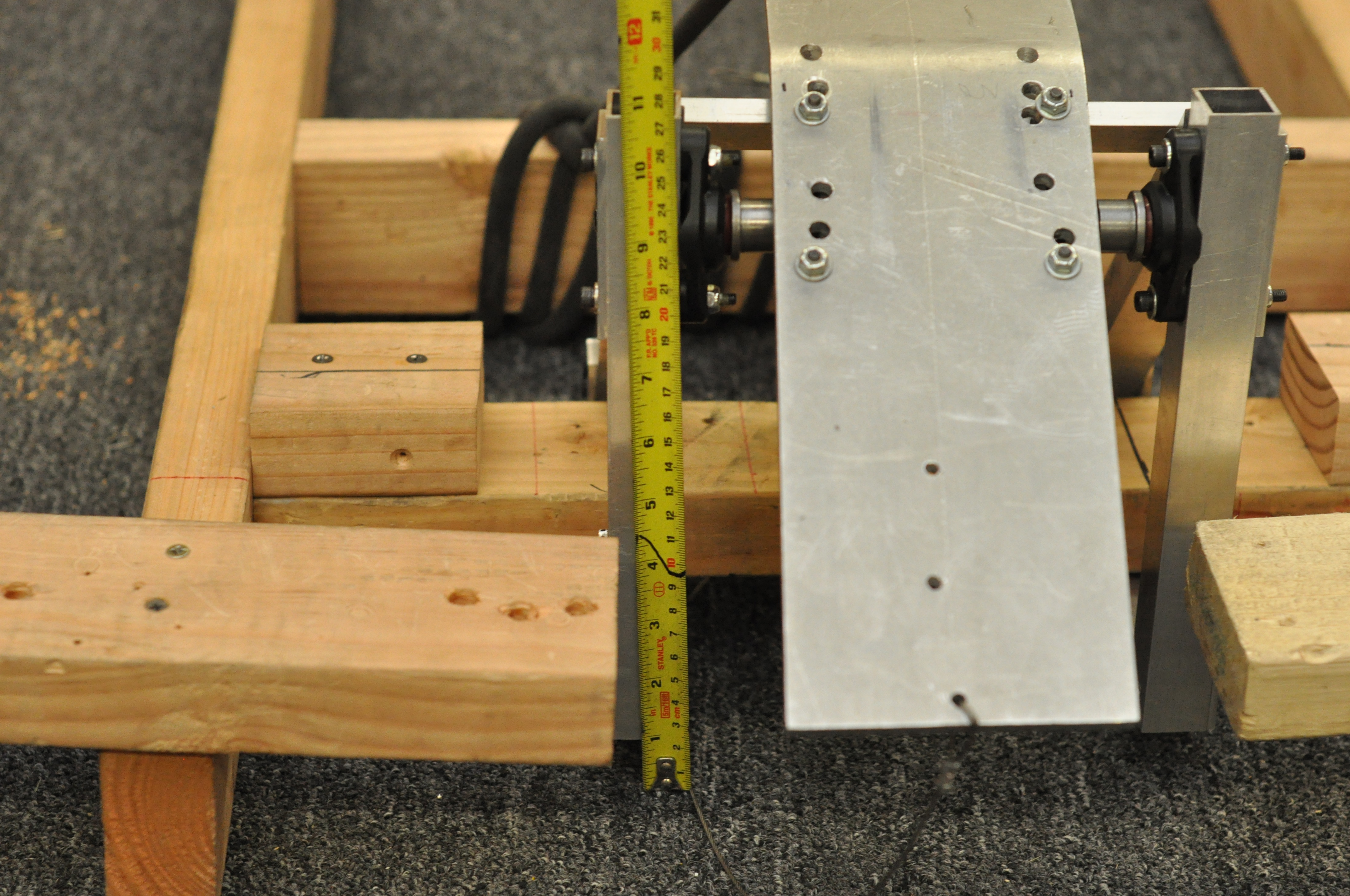
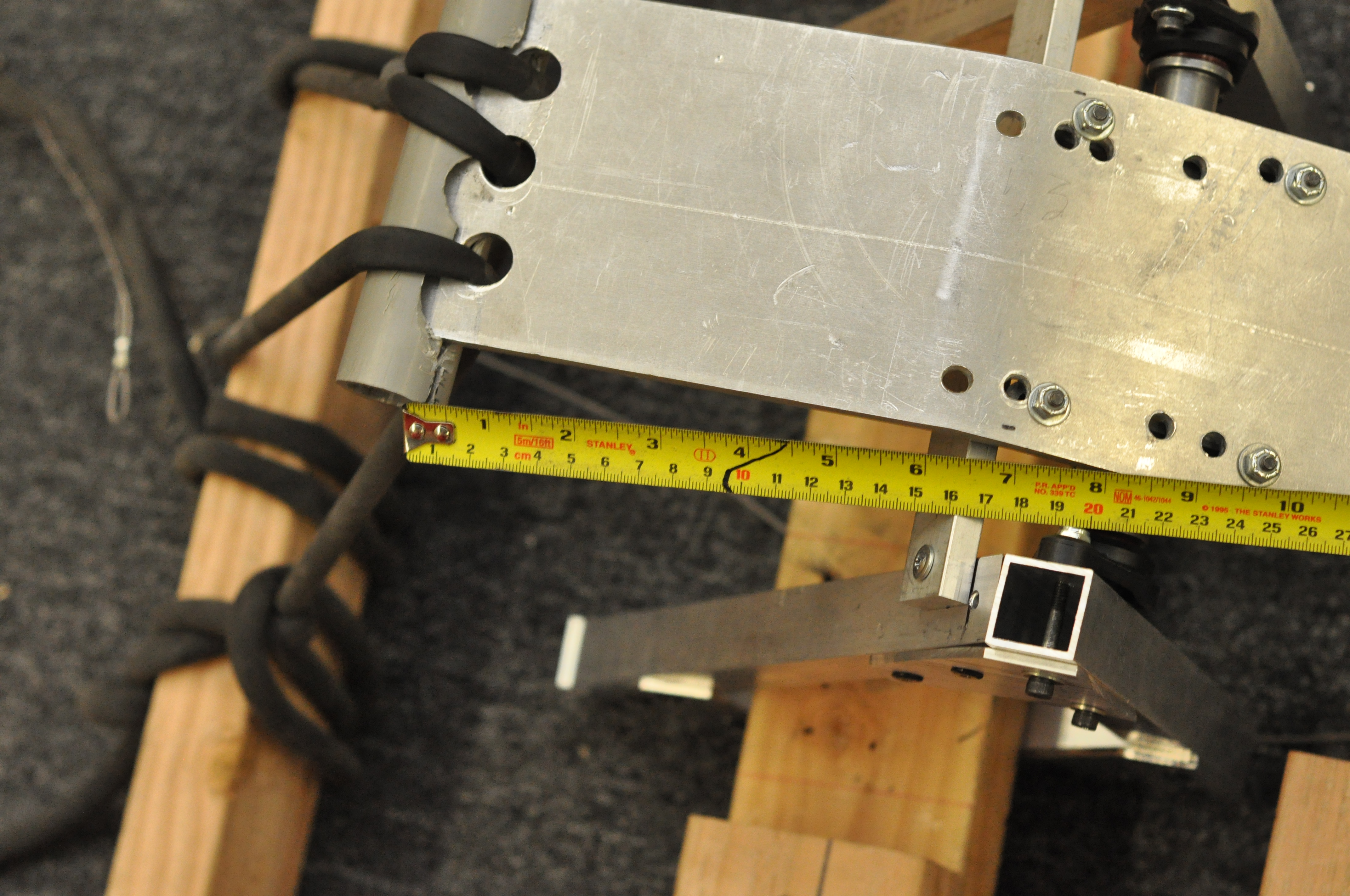

Ball launching assembly launches ball out of the field when set at the high power position.
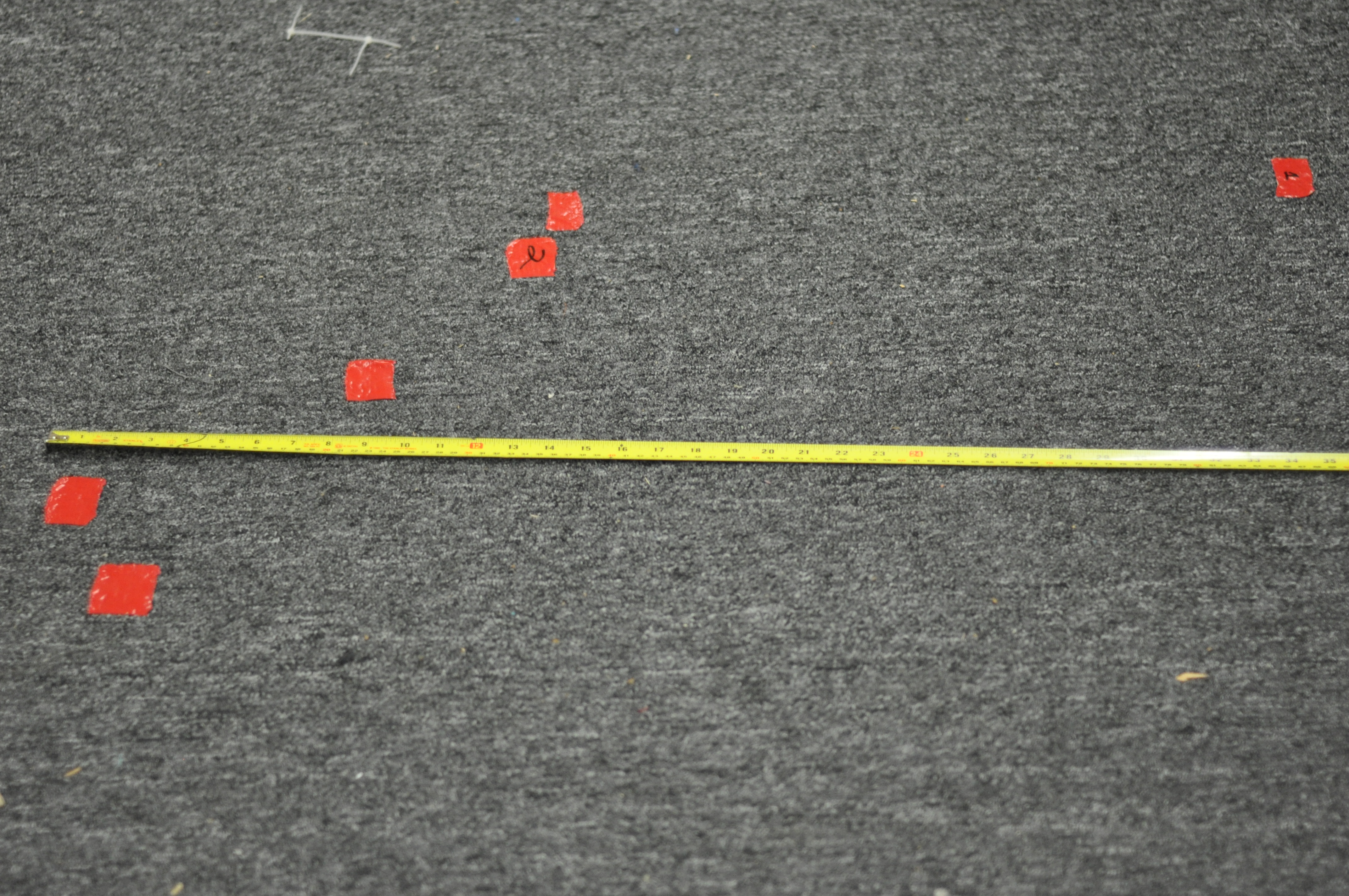
Ball launcher assembly launches ball 44ft on the low power setting.
Here’s the hit spread photo after a few test shots.
CAD and Prototyping Progress
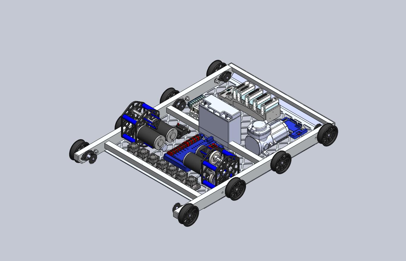
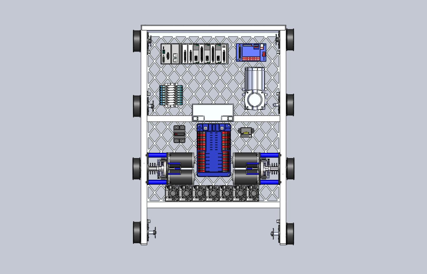
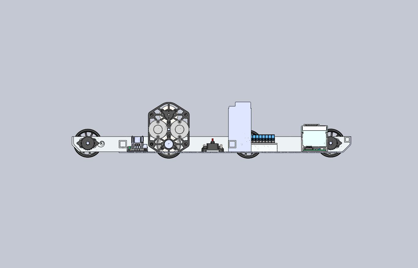
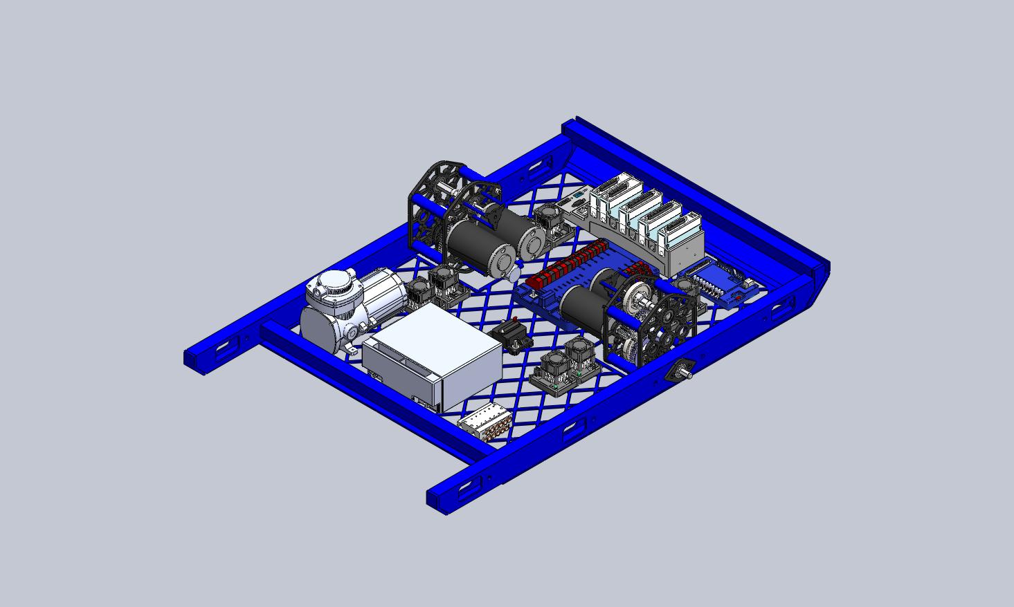
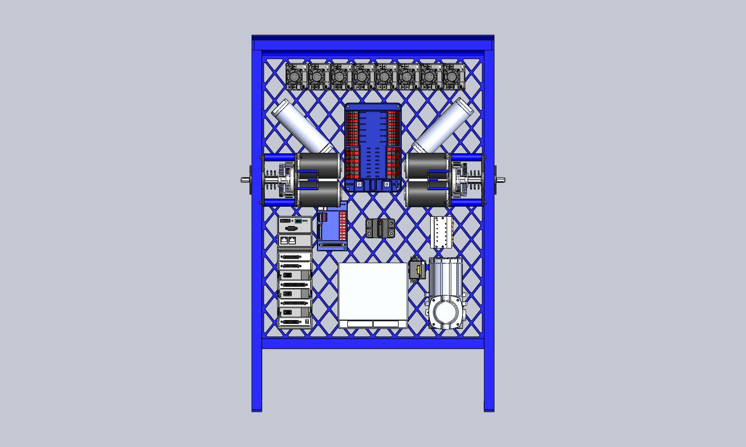
Today, Team 254 prototyped a mechanism that keeps the ball in place while kicking and helps the release of the ball. We also mounted the kicking prototype onto our drive base prototype, and began to mount the holding mechanism. We completed the CAD of our basic drive base, and came up with possible placements of the electronics board, as seen in our earlier post.
CAD Progress
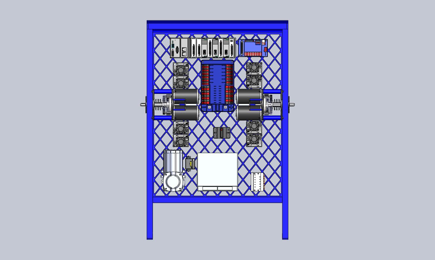
Today, the CAD team continued to work on the drivebase frame. The back bar for hanging was scrapped, out of concern that there would not be ample room between the bar and the bumpers for an alliance partner to get a hook in. We extended the base plate to the very back of the frame and started to lay out electronics. We are starting to think about what our ball handling mechanism will look like, and how to design the electronics to stay within the constraints that the ball handler gives us.

Organization & Machining
At the lab yesterday, the team continued working on improvements to their prototype . The machining of the wheels has started, meaning we will soon be working on the tread for the wheels. Finally, the team began organizing the bins filled with old motors and parts, as well as locating bearing blocks for the robot.
Drivebase Design & Manufacturing Progress
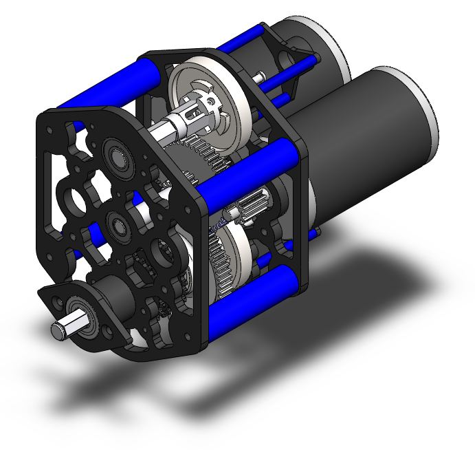
At the Cheesy Poof lab today, several objectives were accomplished. The gearbox design was finalized. The drivebase design moved forward, and the basic frame is set for it. It features a large tube on the back for alliance partners to hang their robots from for bonus points. The electronics board will mount between two square tubes.
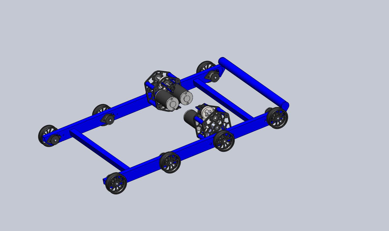
The manufacturing team continued on the manufacturing of the Bearing Blocks. They are about 1/2 done with the 2nd operations on all 140 bearing blocks, and will finish tomorrow. A group of students cut metal stock for the wheels, on which machining will begin tomorrow.
Vacuum Suction Testing
Since the ball may only roll 3 inches into the robot, we wished to study the plausibility of a vacuum holding system. In the 2008 Overdrive game, Team 1771 successfully used a mini shop-vac impeller driven by two Fisher Price motors, to posses and lift the 8lb track ball. For our test today, a Shop-Vac brand “Hang-Up Mini” model was used. This is a 120VAC 6.2A model. As shown in the picture below, the impeller is approximately 4 inches diameter, one half inch thick, and very light weight.
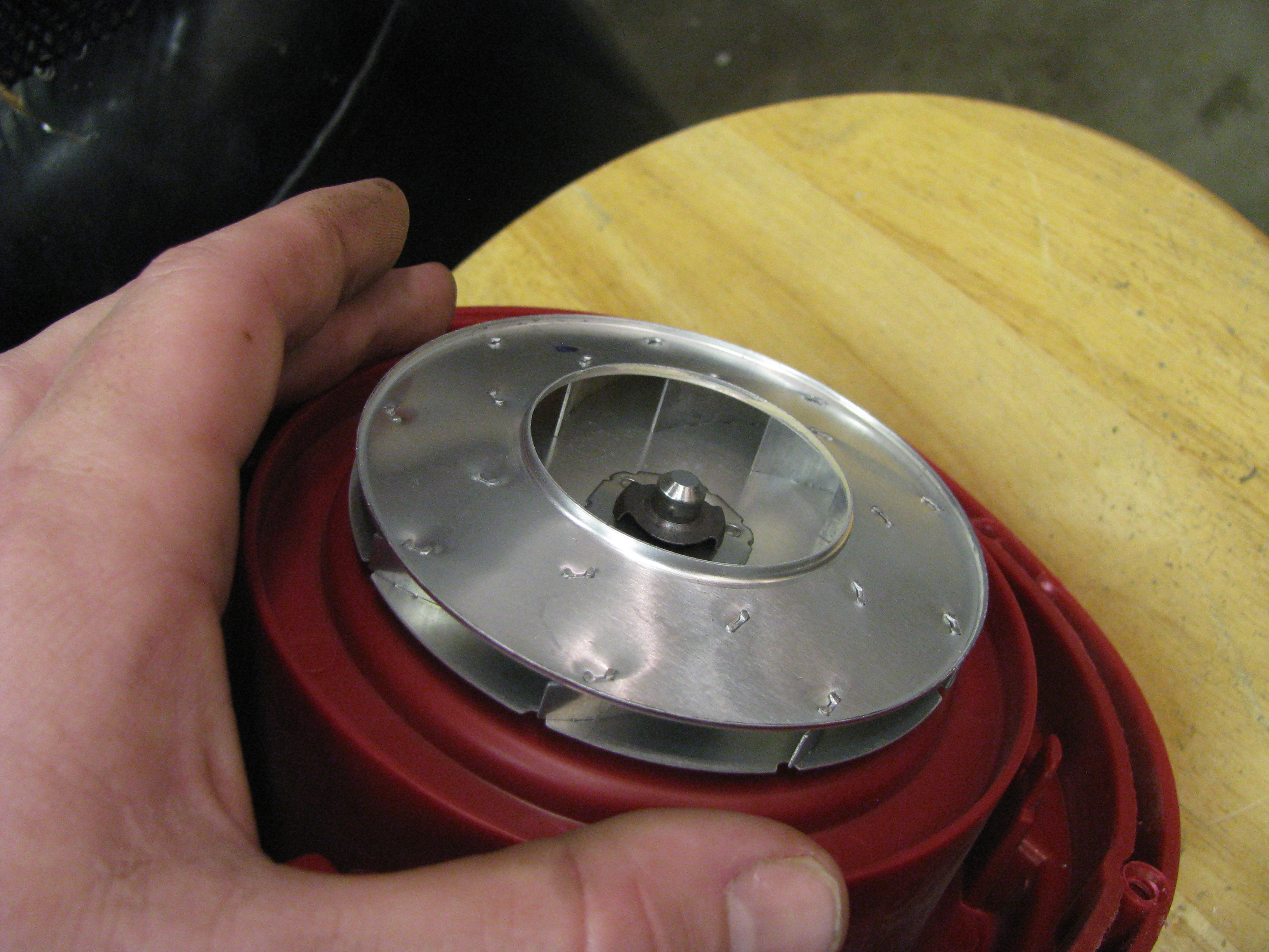
After reassembling the vacuum, a plastic funnel of approximately 4 inches diameter was affixed to the hose. A small basketball and a rubber exercise ball were used for the test (no soccer balls available at testing location). No seal was used around the lip of the funnel. The vacuum held the small basketball very well, and the large exercise ball moderately well. While seams in the balls did not greatly affect the holding power, we speculate a larger funnel with a lip seal/gasket would improve the results greatly.
A video of the test is shown below:
Original video unavailable.
We have not yet determined exactly how a mechanism like this might integrate with a kicker.
We also observed the suction power directly from the impeller housing:
Original video unavailable.
The testing revealed the vacuum produced greater suction and holding power than expected, and could potentially be a successful soccer-ball holding device. Further tests would have to be done to power the impeller with KOP motors (such as two Fisher Price motors, as 1771 did in 2008).
Ball Launcher Prototyping
Earlier today, RAWC students and mentors brainstormed ideas while at the high school, coming up with a few mechanisms to launch a soccer ball. A few of those ideas were actually plausable(we went forward with one). We built a launcher frame that takes into account the size restrictions placed on teams(Ball can only be 3″ inside the ‘bot, Launcher mechanism can only protrude 2″, Ball must stay in contact with the floor).
Here’s a photo of the launcher.

Here’s the release mechanism:
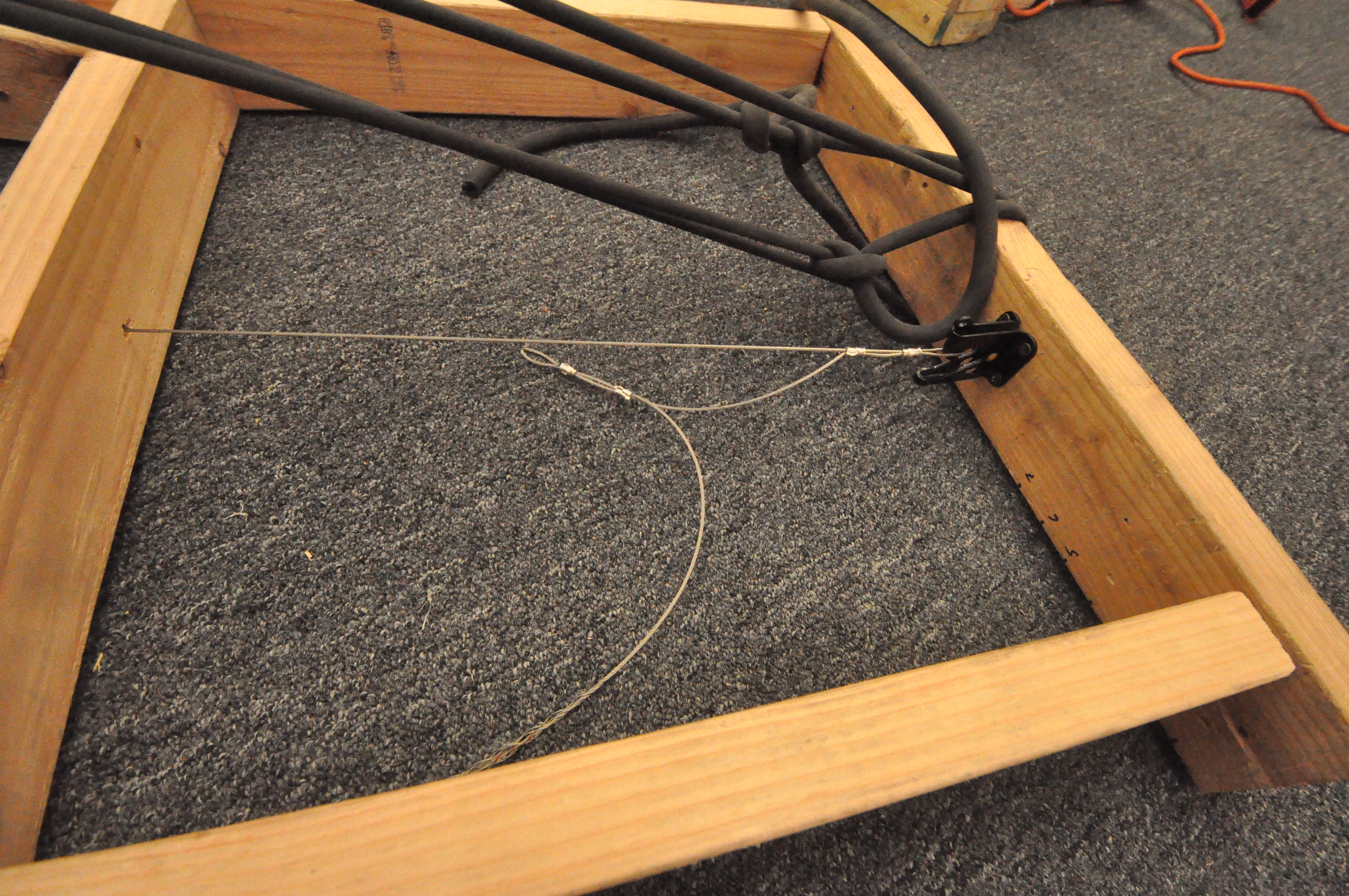
Here are a few videos:
Long Range (Corner to Corner) Preset Test. This test was setup having the launcher’s frame(the size of the 2009 base) touching the wall of an alliance station. The frame was also pointed toward the opposite corner(diagonally). After launching the soccer ball using the long range setting, the ball landed approximately 2 feet away from the opposing alliance’s home zone.
Original video unavailable.
Mid Range (Corner to Corner) Preset. This test was setup having the launcher’s frame(the size of the 2009 base) touching the wall of an alliance station. The frame was also pointed toward the opposite corner(diagonally). After launching the soccer ball using the mid-range setting, the ball landed close to the midfield divider.
Original video unavailable.
Ramp Contact Testing. This test was configured in a way that a KOP tote was placed in varying distances from the front of the soccer ball. We tested the following scenarios: Tote 4FT from ball(long range), Tote 4FT from ball(mid range), Tote 2FT from ball(long range). During our testing, we determined that the ball does not come close to touching the tote in all of the configurations. We performed one additional test that was not documented; the tote was placed 2FT from the ball and the launcher was set into the mid range position. The ball clearly comes in contact with the tote, altering the trajectory of the object.
Original video unavailable.
Additional ramp contact testing. These videos include a plane that is angled to a 45 degree slope. In addition, the ball is in contact with the inclined plane. This test was to demonstrate the launcher’s capability to launch a soccer ball accurately in the case that it was touching the ramp.
Original video unavailable.
Angled ramp contact testing. This test is to demonstrate the effects of using our launcher while being offset from the ramp.
Original video unavailable.
Build Day 5
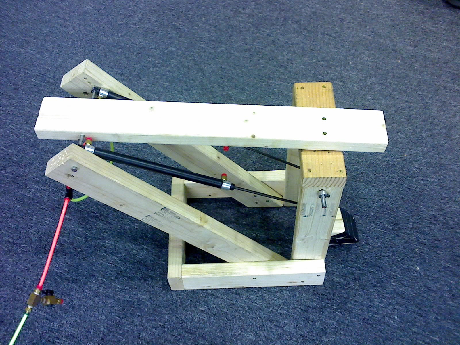
Today at the Nasa lab we had roughly 12 students experimenting with various prototypes for kicking/launching mechanisms. One group seemed to find particular success with a pneumatic-kicker, which was able to launch the ball just over the hump attaining a distance of about 15 ft.
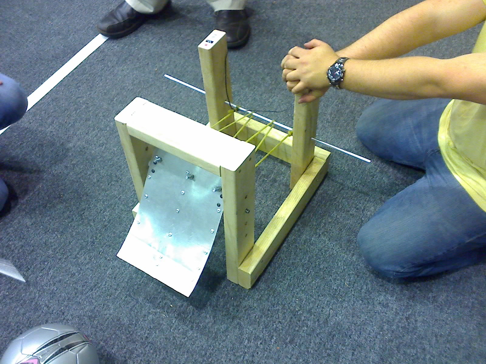
The girl scouts also came up with an interesting concept of a surgical-tubing powered scoop. This design may be promising, but has not been sufficiently tested yet.
Meanwhile the design team worked diligently upstairs properly tolerancing the gearbox and shafts as well as designing the 4″ wheels (see previous post).
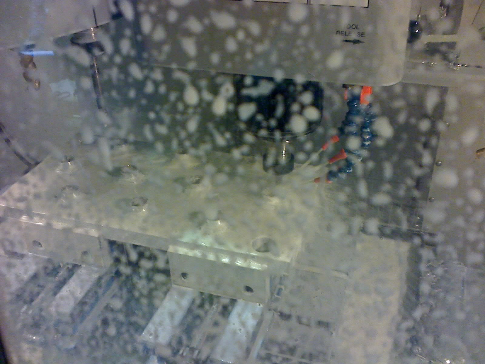
In the machine shop the CNC began rolling out the bearing blocks, doing the second pass. By the end of tomorrow the bearing blocks should be ready for anodizing (provided there are no unseen complications).

Tomorrow the material for the wheels needs to be cut out so they are ready for machining. Pushing or launching the ball past the ramp has proved difficult, requiring excessive propulsion or front-spin and we will continue prototyping different designs.
Wheel Design
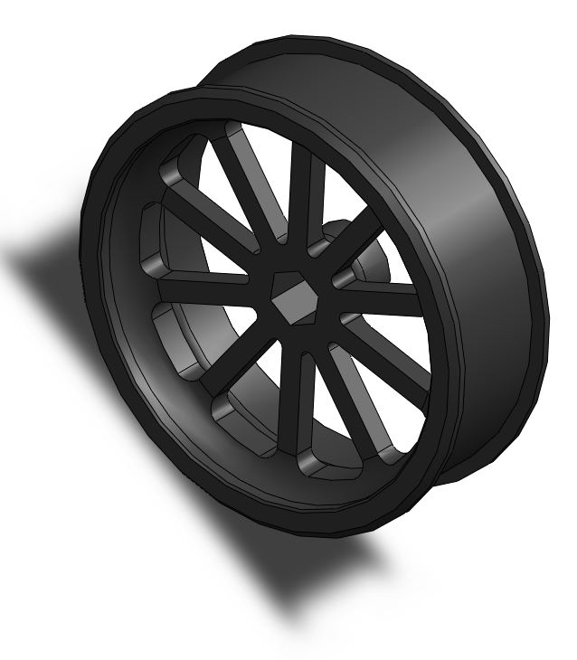
The wheel design has been completed. The wheels weigh 0.30lbs each and construction will begin tomorrow.
Manufacturing Progress
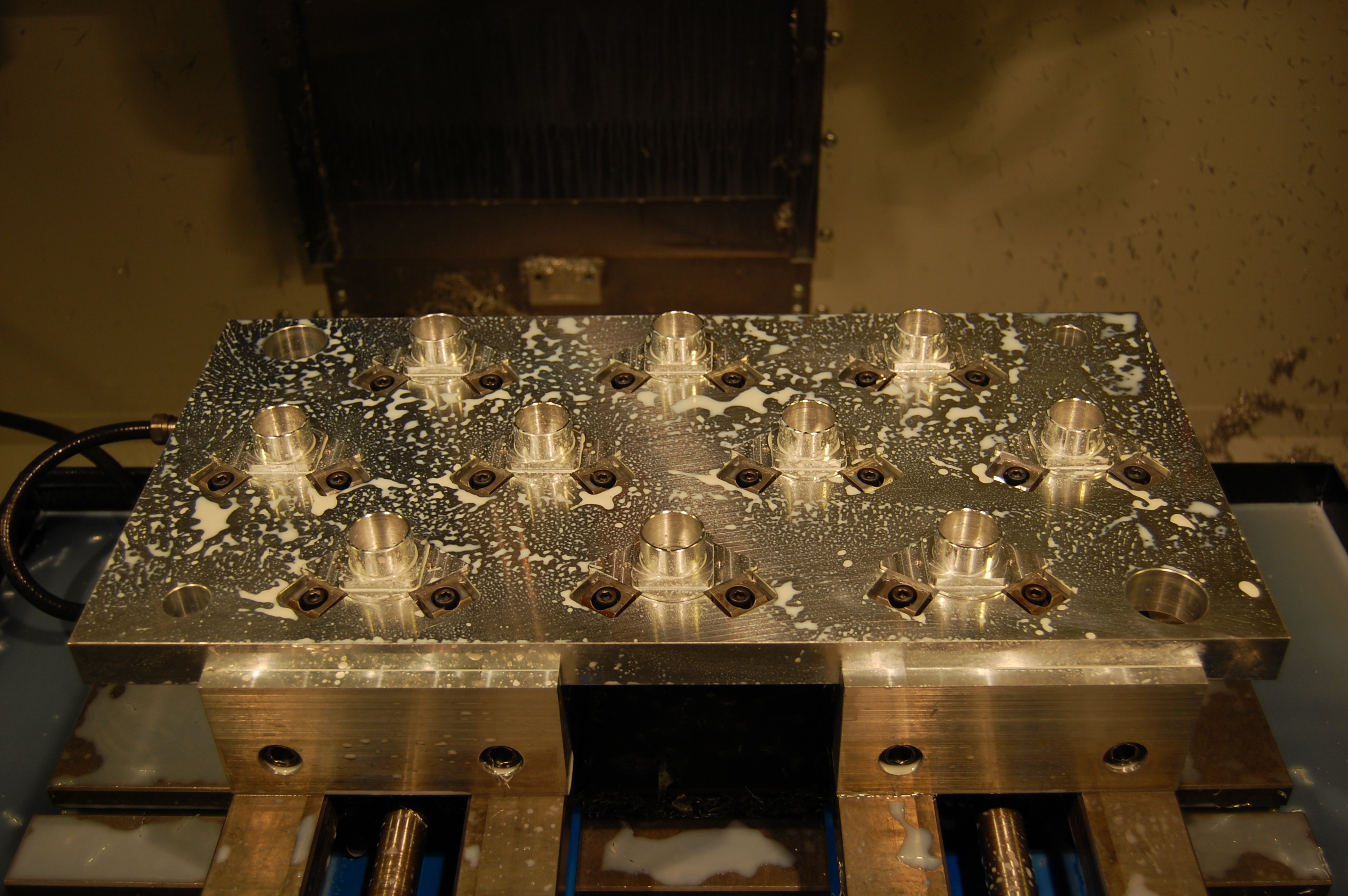
Today we finished the first operation on all 140 bearing housings. We began machining the backsides of them and expect to be finished tomorrow evening or early Friday, at which point we will begin machining wheels.

Build Day 4
At Team 254’s lab today, we had an extremely large number of people working hard to complete some common objectives.
In the manufacturing department, several students continued cutting stock for the bearing blocks. Many of the bearing blocks have already completed their primary operation on the CNC mill.
In the design department, a very large group of students worked downstairs all afternoon to continue to develop prototypes for ball launching devices. Some have been modified and improved to be tremendously more powerful than their previous states. Upstairs in the CAD department, a small group worked hard all afternoon to CAD the Drive Gearbox. As of 10:00 PM, the gearbox shafts are mostly done, but still need to be toleranced, which will be completed tonight to finalize the shaft drawings. In the morning, the drawings will be sent to 968 and Pacific Precision for the shafts to be completed this week.
This week, the design team will finalize the gearbox and design the drive wheels so that the gearbox plates can be manufactured by Team 233 in Florida. The manufacturing department will continue to manufacture the bearing blocks and will move on to the wheels once the bearing blocks are completed.