
2018 FRC Build Season Blog
Build Blog Days 2 and 3 (1/8/18 – 1/10/18)
Drivebase
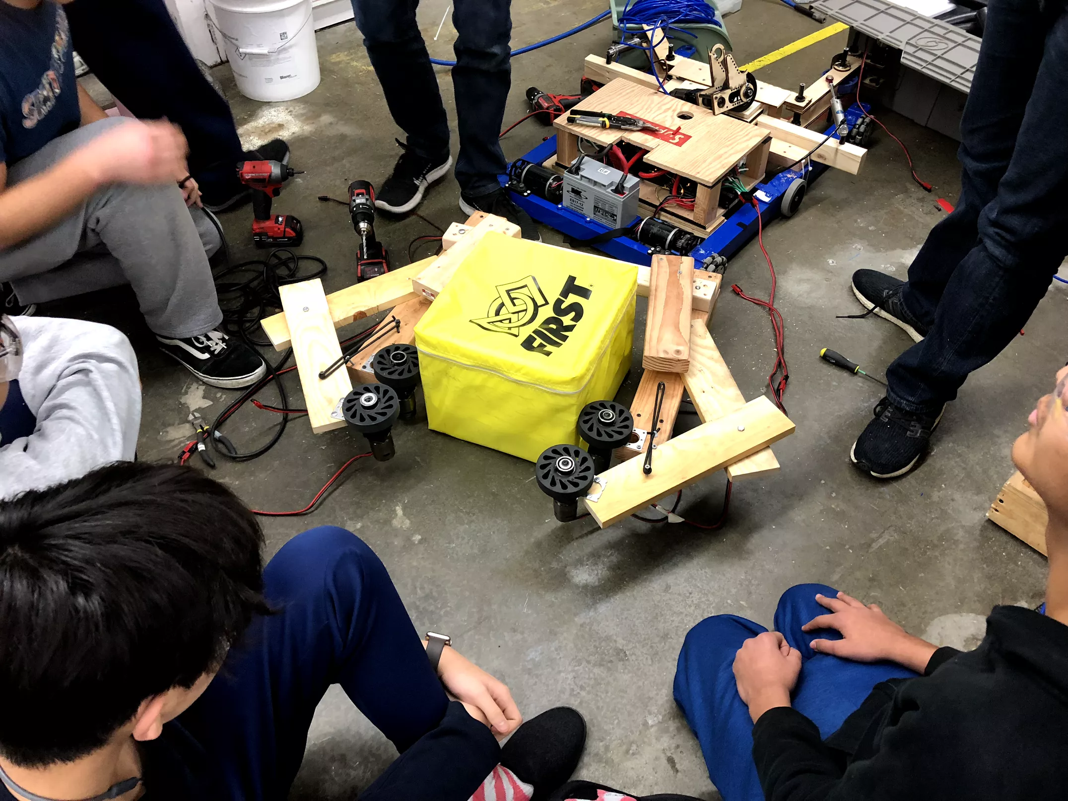
Task: Test drivebase with modelled dimensions (28"x33") 1.15” center drop; from top of frame rail and placed 2.5” from the front and back of the drivebase frame high centering on the ramp at various angles.
-
When approaching the ramp perpendicularly, the robot clears the ramp and does not high center. However, when it approaches at angle towards the corner of the platform where the front and side ramps meet, it high centers. Also, when the robot is travelling up the ramp with the cable protector below it, The back of the drivebase frame contacts the cable protector and high centers on it. The drivebase modelled with these dimensions in CAD accounts for a 16 tooth sprocket with chain OD and a 0.1" clearance between the sprocket-chain OD and the baseplate. In addition, the 4" colson wheels used are actually 3.9" wheels. If we were to bring the sprocket lower to the baseplate and use fully 4" wheels, there is a possibility it would not high center. We need to investigate the lowest we can go with the sprocket-chain OD and test with new 4" wheels. Additionally, these results may change our driving strategy where we will only attempt to go up the ramp perpendicularly. See these videos to see the drivebase in action.
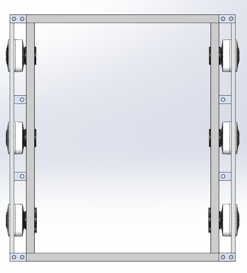
Task: CAD drivebase weldment and begin work on drivebase assembly
-
We designed the drivebase frame rails such that the wheel placement and center drop can be easily modified as they are yet to be finalized. We went with our traditional West Coast Drive using 4” colson wheels. Assuming we will want to carry our partners while climbing, we need to beef up our drivebase, whether it be using thicker box tubing or by adding cross members. We will perform a bending calculation on different sizes of box tubing to determine what is the best size to use. Regarding bumper mounts, we currently see to ways to approach the task. The first way is a 2014 style bumper mount with latches on the drivebase frame that latch onto mounts on the bumper. The second way is a 2017 style bumper mount that uses guiding rods that go into the drivebase frame and some other latching system. The 2017 is definitely a harder bumper mount to work with, however, the straight face with mounting provisions may prove useful if we decide to deploy ramps for our partners to climb up on. We will investigate this in a cartoon CAD.
Task: Drivetrain gearbox design
-
We decided on a triangular configuration of mini-CIMS, with ratios that yield about 10ft/s and 18.6 ft/s. We are now trying to figure out how to package the shifter cylinder into the gearbox below the CIMs. We are exploring either a smaller bore cylinder or a nose-mount piston instead of pancake. Changing from 3/4 to 9/16 bore reduces the shifting force from 22lb to 11lb; Further testing is needed to see if this is enough force to shift. Regular air cylinders can be used if it is ok that they stick out longer than the CIMs. The next steps are to finalize which shifter cylinder we want to use, model the rest of the gearbox plate, and then detail in the entire gearbox assembly with Cheesy Parts.
Intake
Task: Test intake prototype with pivotable arm
-
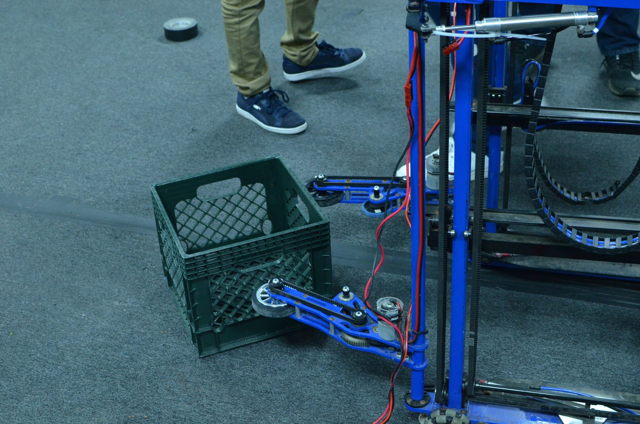
We assembled the intake prototype and mounted it to the 2015 drivebase to test. We were able to run a few tests with a single set of wheels, but unfortunately, as the intake was made out of 0.25" plywood, a part of the arm broke off and we were unable to gather any further data.
Task: Test 2015 Simbotics style intake prototype with pivot wheel sets
-
We initially based the intake prototype off of 2015 Simbotics’; with the first set of wheels pivotable but not the second set–we spaced out the second set to be tangent to the cube when it is 13" width. When intaking a cube in a square position, the intake easily worked, however, when intaking a cube in a diamond position, the cube got trapped between the first set of wheels which were able to pivot to comply to the cube's shape and second set of wheels which were stationary. To fix this, we made the second set also pivotable and were able to intake a cube at different angles. We hooked up the motors on the intake to the drive talons on the development board and were able to simulate different speeds for different sides by turning with the control board joysticks. With different speeds, we were able to force the cube to rotate into a square position in a certain direction which shows that some amount of asymmetry may be necessary to intake cubes. We will continue testing this intake on the field carpet to account for the friction between the cube and field and will further design this in CAD into a stronger prototype.
Programming
Task: RPILIDAR Driver
-
We finished up writing the driver and implementing all necessary methods. The driver is ready to be tested once the LIDAR sensor arrives.
Task: LIDAR Visualizer
-
We continued work on the LIDAR visualizer. We set up a Node JS server that recieves LIDAR point data encoded in JSON from the roboRIO using Network Tables. The server then uses websockets to send this information over to the viewing page. We also continued work on the visualizer interface. It can now plot fake JSON data, but needs to be hooked up the the websocket so it can display a continuous stream of data from the LIDAR sensor.
FRC Build Blog Day 1 (1/6/2018)
Here is the 2018 game animation.
Game Analysis
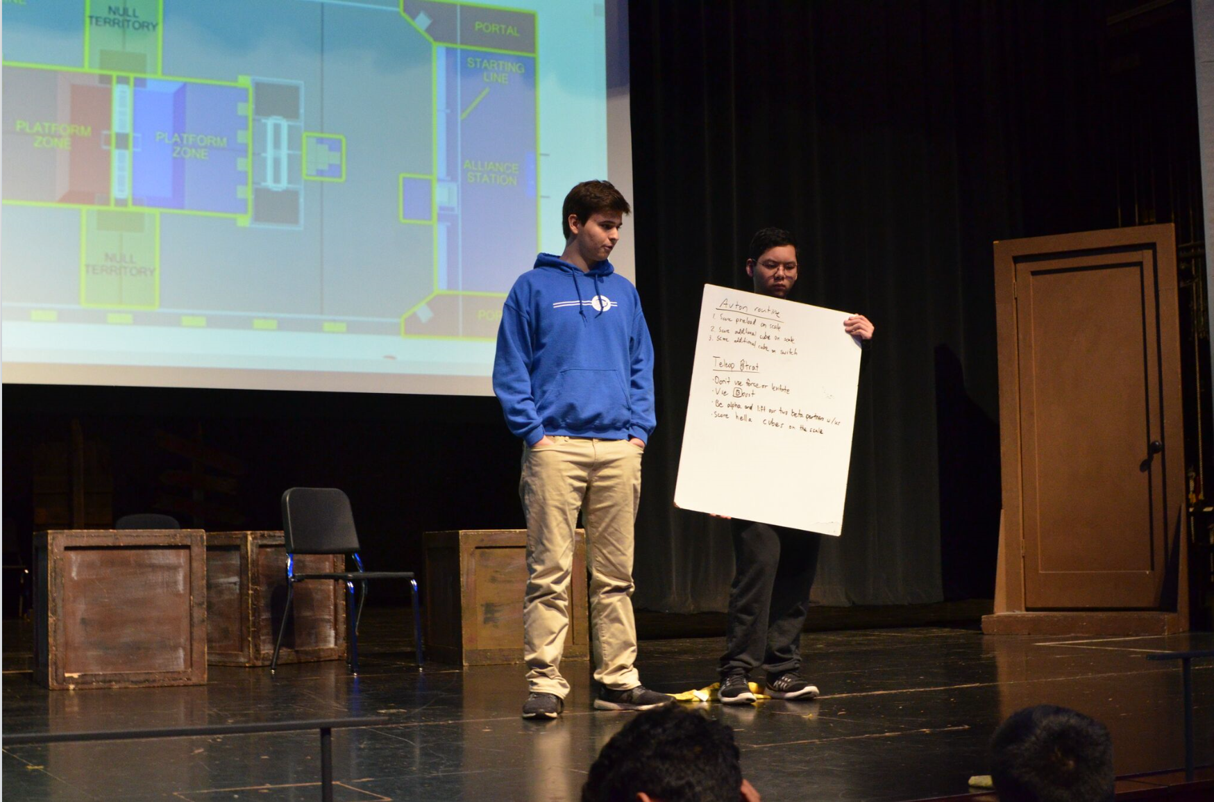
This year’s game involved many variables, requiring a strategy that succeeded in performing all tasks presented in the challenge. With the power ups, scoring based on points/sec, randomized sides, and the difficulty of climbing, no straightforward strategy which ensures a win presents itself. After trying various combinations of scores, we concluded the best way to maximize our points would be during autonomous when the scoring is scaled by a factor of 2 and during the endgame when each climb is worth 30 points. Since autonomous scoring is worth more than tele-op scoring, we decided that autonomous scoring was a major priority to stay ahead during a match. We planned for short paths to score cubes (<30 ft), so drivetrain acceleration and our ability to score from either side of the robot was critical for rapid cycles. We debated between starting off on the middle or side of the field. If we were to start off on the middle, we would have an equally distant route to reach the switch and scale. However, we could not guarantee the successful completion of our autonomous route as our alliance partners may get in our way. If we were to start on the side, we may either have a very long or a very short route to reach the switch and scale. However, we could guarantee the successful completion of our autonomous route as our alliance partners would not get in our way. During the endgame, we aimed for having all 3 robots climb or by having 2 robots climb and 1 levitate.
Drivebase
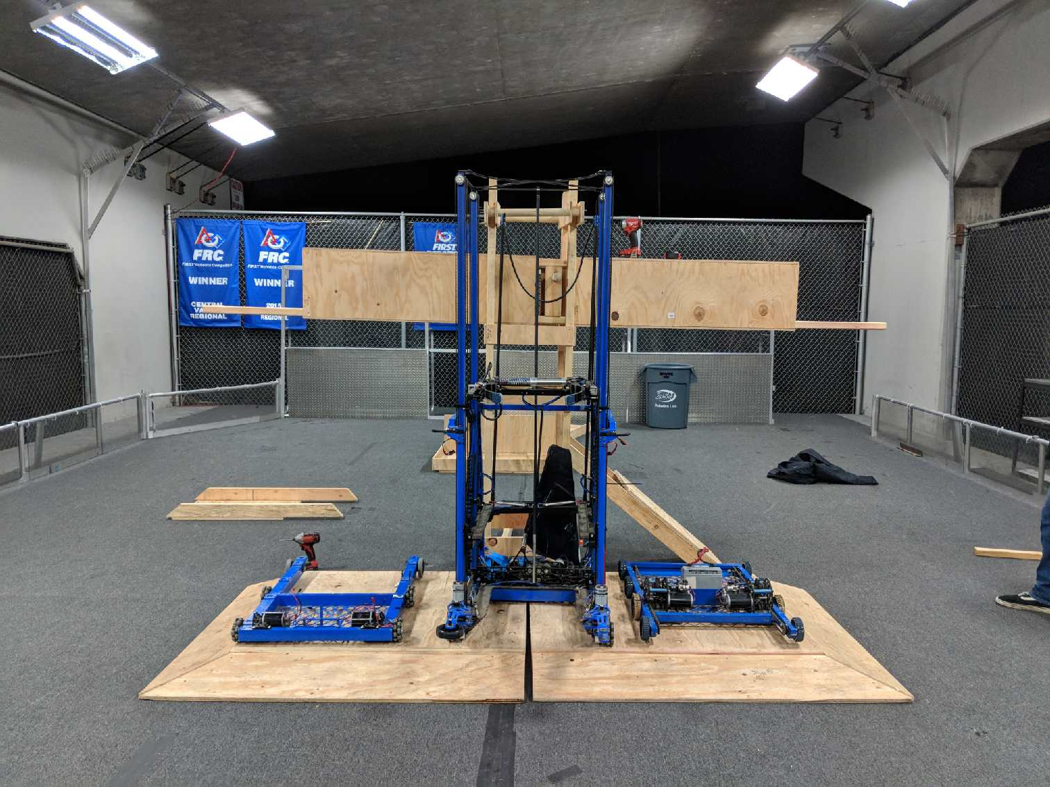
Task: Fix 2015 drivebase and prototype if it can go over the platform ramp
- We fixed the 2015 drivebase which was missing a control system. We mounted our development board on the drivebase and programmed it to drive, but immediately saw issues as it went up the ramp. Because of the long wheel base and short distance between the wheels and the ground, the drivebase high centered on the ramp when the bellypan came into contact with it. This result shows that for our 2018 drivebase, we will need a shorter wheelbase and a greater centerdrop.
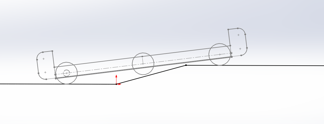
Task: Model drivebase motion up the platform ramp
- We modelled in CAD the motion of a possible 2018 drivebase going over the platform ramp without high centering. We tweaked two factors (distance of outer wheels from side edge of frame rail, center drop) until we arrived with the dimensions of a drivebase that would safely clear the ramp with 4 wheels (2 on each side) always contacting it and without the bumpers or bellypan ever contacting it.
Intake
Task: Fix 2015 intake and prototype if it can intake Power Cubes
- We fixed the 2015 intake which was initially missing the intake wheels, shafts, and timing belts. We used this intake to prototype the intaking of the Power Cubes. We did see some promise with this intake, however since it was designed for the tote and not the Power Cube dimensions, we were not able to efficiently intake the Power Cube. Moving forward, we plan on testing out different wheel materials to contact the Power Cube as it is being intaked and will design/prototype an intake with the correct geometry to fit the width of the Power Cube.
Field Prototyping
Task: Test coefficient of friction of Power Cube on scale plate
- We wanted to calculate the coefficient of kinetic friction between the Textured HDPE and the fabric of the Power Cubes. To do this we looked at how high we had to lift the straight piece of HDPE before the Power Cube started to slide down. From this we calculated the angle formed and the coefficient of kinetic friction which ended up averaging to about 10.32 degrees and 0.18, respectively.
Task: Test geometry of 3 robots on the platform
- We laid out the spacing of three robots on the scale platform to see if it was physically feasible of having 3 robots side by side with enough space for the robots to maneuver to those locations. It seems that it is possible for 3 robots to fit on the platform.
Task: Find what angle does the scale tilt to at its highest state
- At its highest state, the scale tilts to around an angle of 7.662 degrees. Based on our data gathered from the task: “Test coefficient of friction of Power Cube on scale plate”, the Power Cubes will not slide down the scale plate when it is tilted to its highest state.
Field Construction
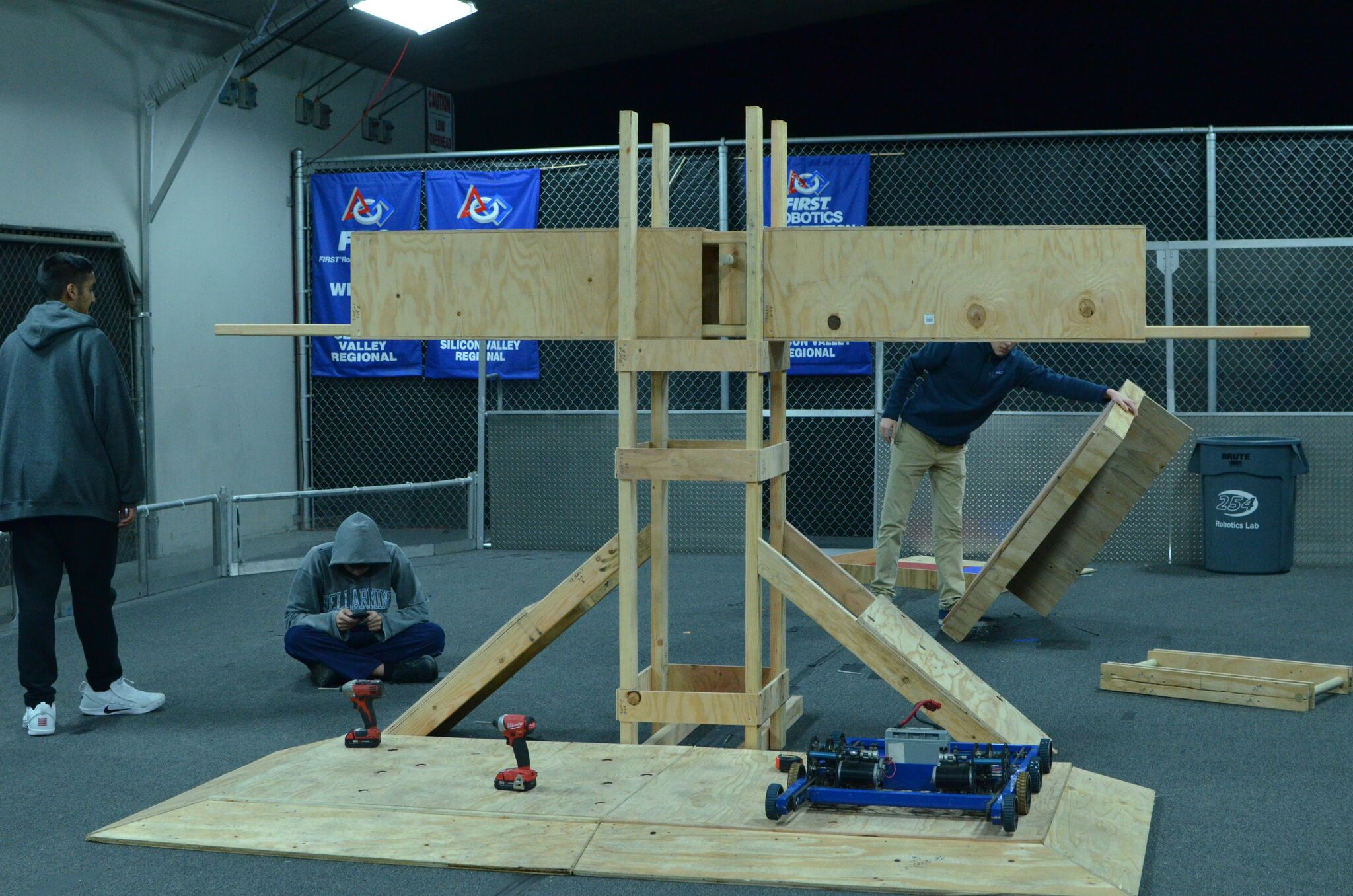
Task: Assemble wooden scale
- We assembled a wooden version of the scale, however we are planning on assembling an aluminum version similar to the scale we will see in competition. This is because we don’t want any differences from the tournament scale from different materials that will arise in different materials (center of mass, weight, friction) which may impact our robot performance and drive our robot design.
CAD
Task: Space claim of 3 robots on the scale platform
- In CAD, we made a space claim of 3 robots, placed them in various arrangements on the scale platform, and looked at the feasibility of having all 3 side by side. It seems that it is possible for 3 robots to fit on the platform.
Programming
Task: Program 2015 drivebase to steer in correct direction with controller joysticks
- When we initially placed the development board control system on the 2015 robot and attempted to drive it, the wheels were turning in the opposite direction to the controller joysticks. We corrected this by reprogramming the drivebase to match with the direction of the controller joysticks.
