
Blog - January 2013
Day 10: Shooter & Programming
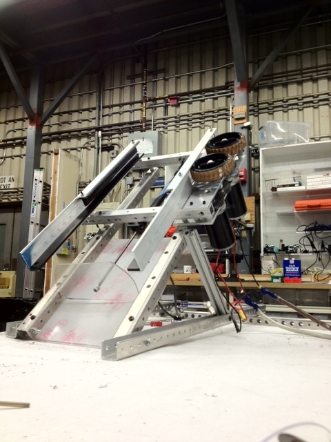
Shooter
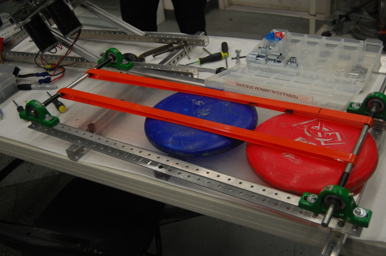
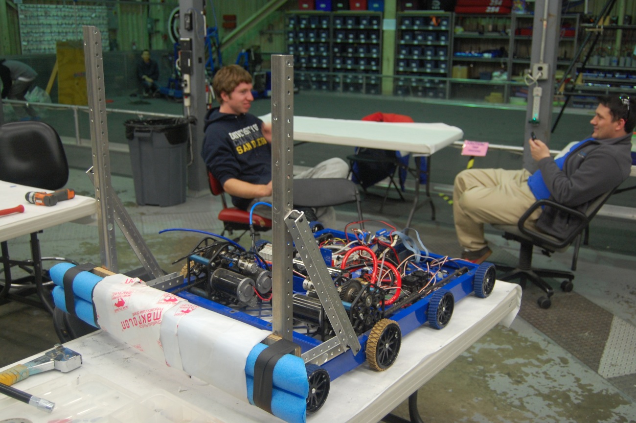
The shooter retained most of its current form in terms of design, some new pieces were just added on. A system for indexing and stacking frisbees was designed and implemented on the prototype shooter, so that it will be able to load several frisbees.
Programming
The programming team had an effiecient day today. Firstly, they worked on the autonomous script and selector. The programmers hope to cycle between hard-coded and on-the-fly autonomous sequences with a press of a button. Secondly, they worked on the Smart Dashboard and the GUI. The team managed to get the FTP connection to work. It turns out that the Apache Commons jar should be placed in the lib/ directory of the Smart Dashboard folder. This has yet to be tested on the driver station laptop, which will be done tomorrow. Finally, they started designing the control board and creating the corresponding list of parts. The team decided on driver and operator controls, such as joysticks, buttons, and switches for the robot's functions. Students also decided on the sensors that would go in the robot (encoders, gyro, etc).
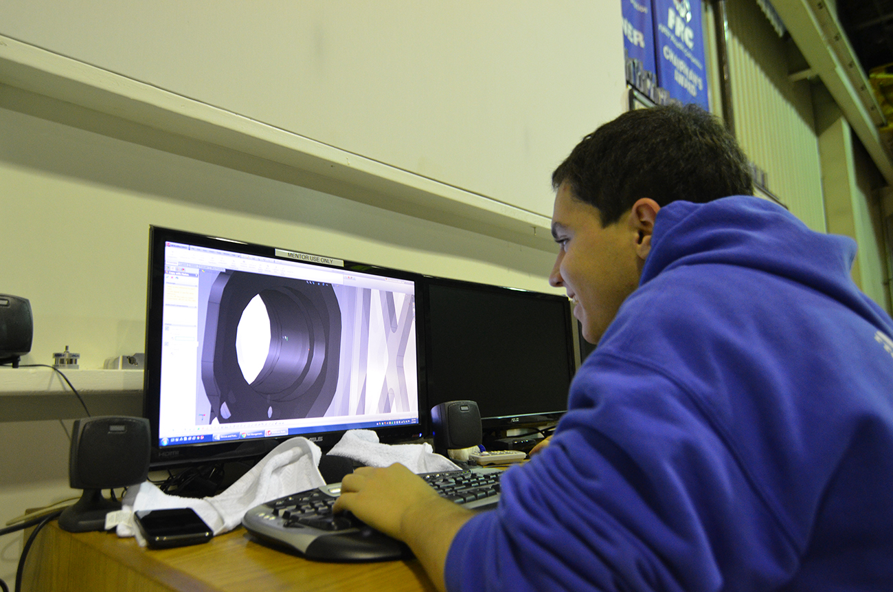
Design
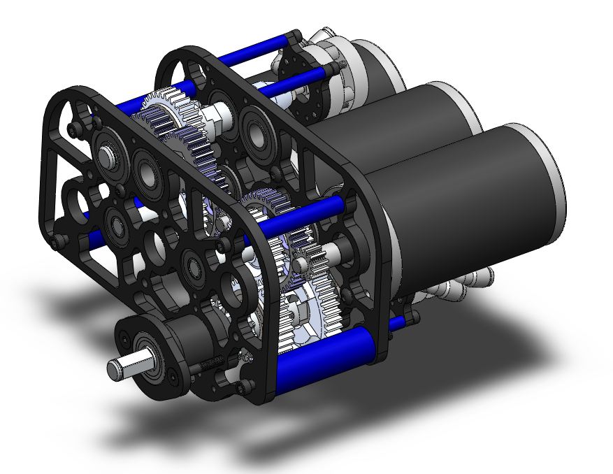
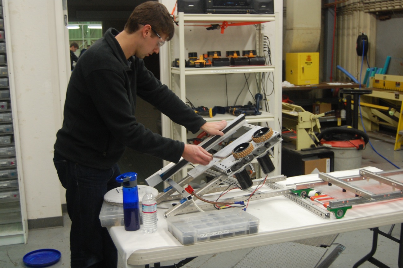
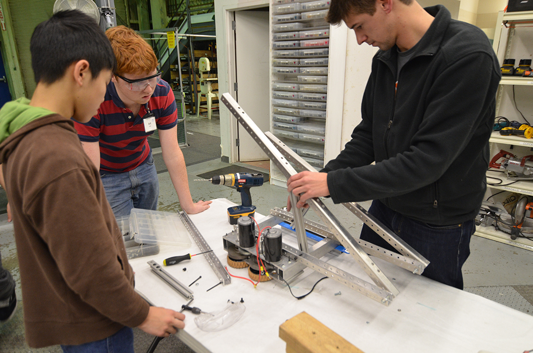
The design of the robot has been coming along slowly but steadily. The team decided on a 6 motor drivetrain utilizing 6 CIM motors. Furthermore, each drive gearbox has a Power Take-Off (PTO) which could be used later to power a hanging mechanism.
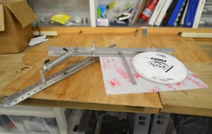
After intake prototypes illuminated potential difficulties bringing disks up such a steep angle, it was brought up that a wider robot would allow for a gap in the bumpers for frisbees to travel through. After a long discussion, this route was pursued and the drivebase weldment (assembly 254-13-A-0300) was finalized and the base plate was sent out for manufacturing by sponsor BAE Systems.
With the drivebase weldment finalized, students worked to make CAD drawings for the components of the weldment. Furthemore, the control board design began.
Miscellaneous
The shipment from Coast Aluminum arrived. It was taken apart, checked and stored with the other aluminum. Some of it was cut to begin manufacturing a few of the smaller parts.
Action Items
-
Finish bumper design
-
Hold a design review for the helical conveyor/indexer
-
Begin prototyping the helical conveyor/indexer
-
Begin cutting drivebase stock
-
Continue work on autonomous selector
-
Test uploading files from Smart Dashboard on driver station laptop
FRC Day-Off, Week 2
Today was our first down day for FRC build. This post will recap a few of the design decisions and design progress so far.
Drivebase Configuration
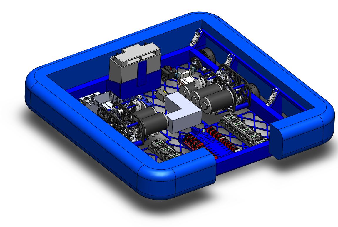
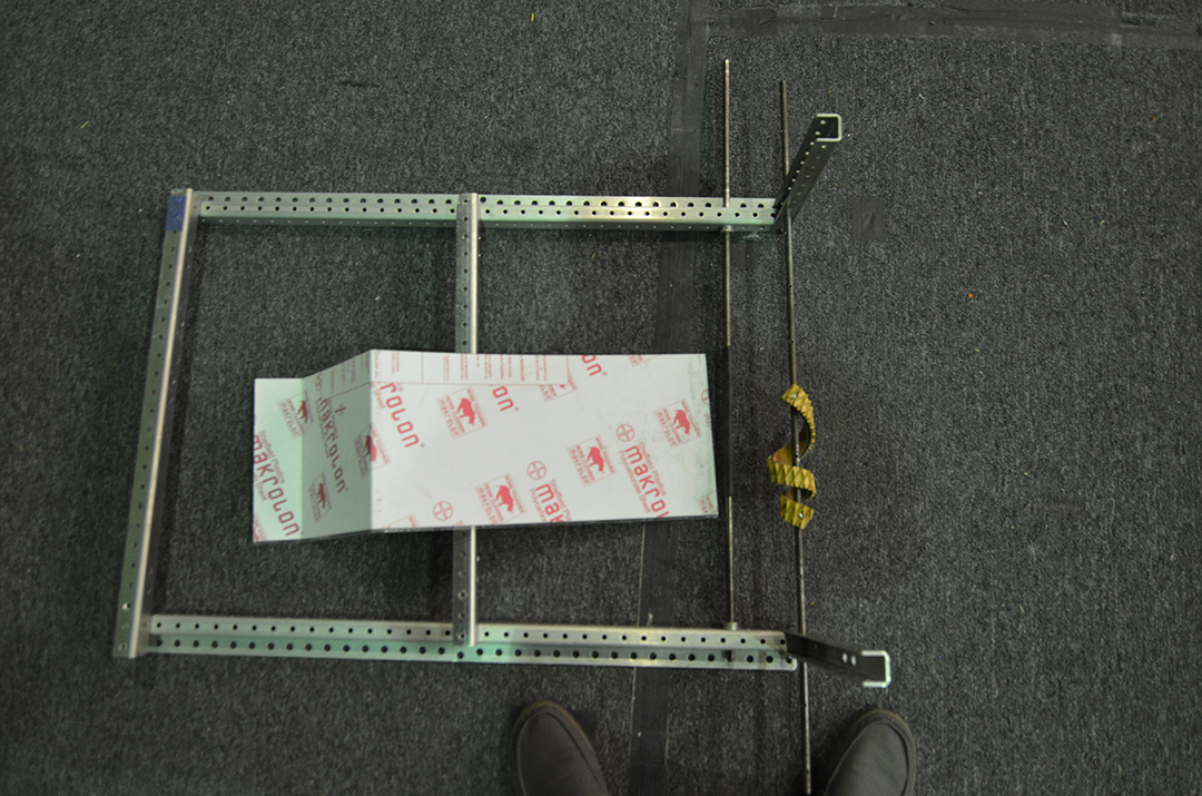
There will be a square drivebase on the robot. This was decided up for the following reasons. The square configuration will give more room for the intake. One of the updated rules was that the the robot cannot exceed a 54" cylinder. Because of this, the shorter and wider robot will allow for more room in the intake to drop down.
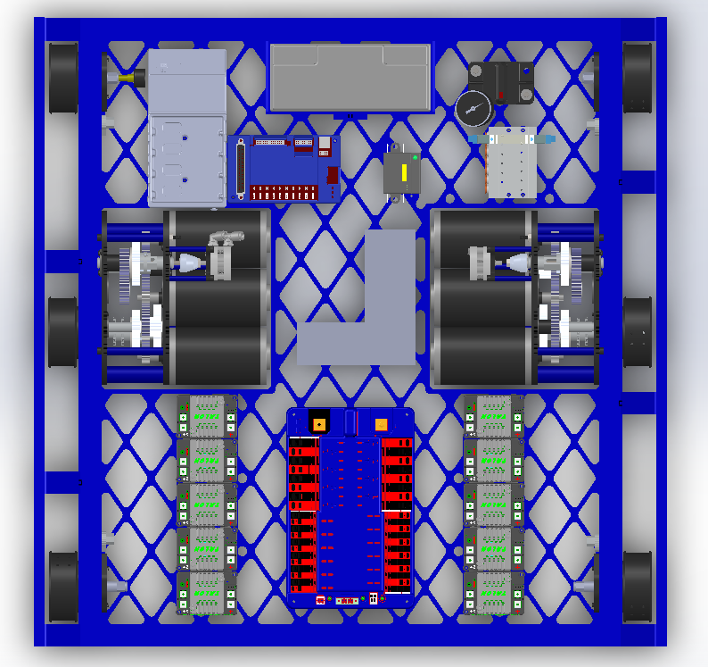
Electronic Layout Done. Baseplate sent for manufacturing
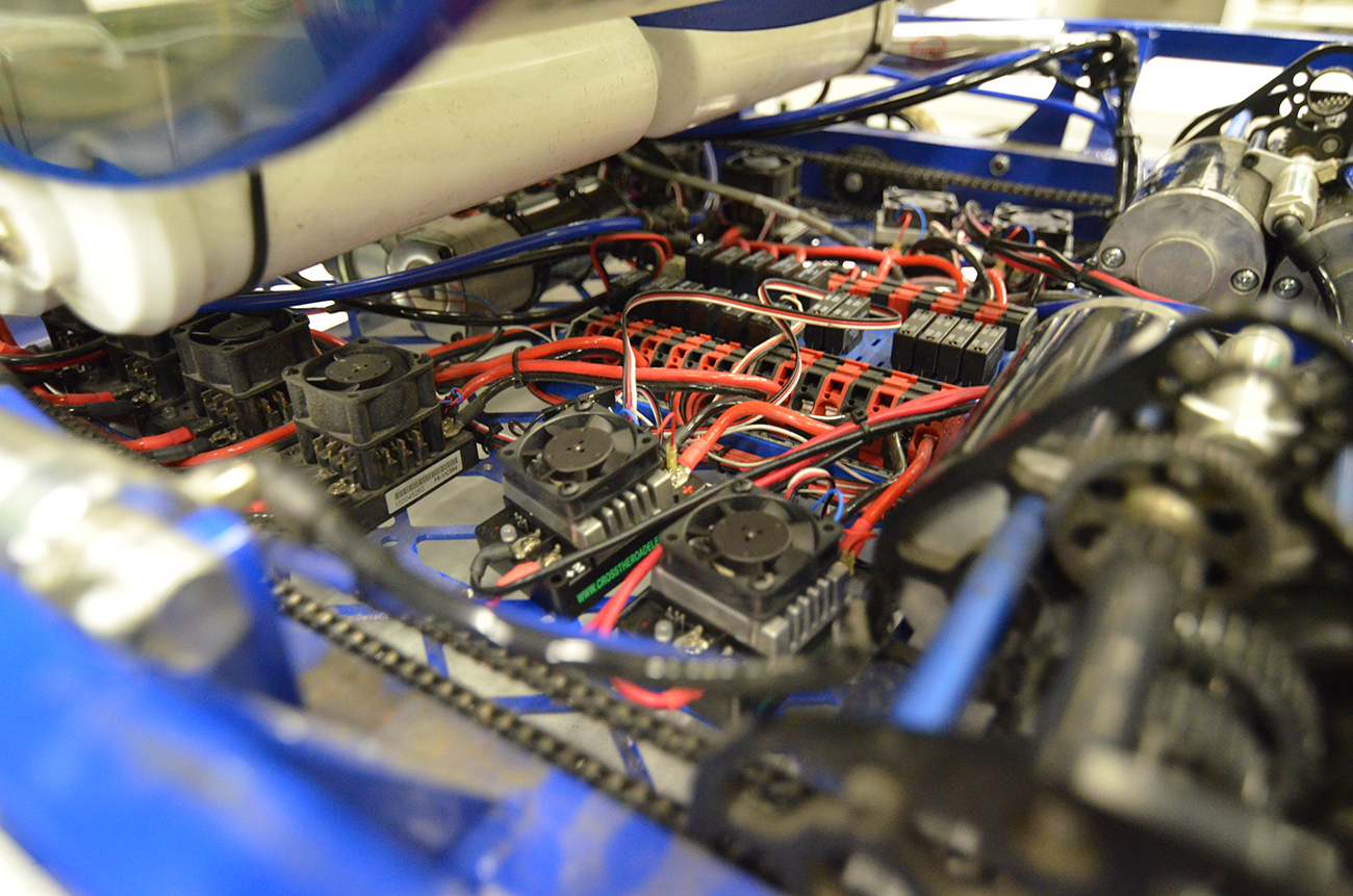
After finalizing the size and dimensions of our drivebase, the next step was to complete the layout of electronics on the baseplate. The batter will go towards the back of the robot (away from the intake) to balance out the center of gravity. The talon speed controllers will be at the front along with the power distribution board. These were all layed out in the CAD model and mounting holes were put in the baseplate. The raw material for the baseplate was cut and was sent to BAE Systems. The baseplate will get waterjetted by BAE and hopefully sent back by the end of the week.
See above for the electronics layout.
Cutout in Bumpers for Intake
It was decided that the bumpers will have a cutout to allow the intake to drop down. The intake will bring the frisbees over the frame rail, but not the bumper. Having the cutout will allow the intake to drop down on a pivot that is lower down. This will give the intake a smaller profile when pivoting down allowing for a bigger intake when fully extended.
Day #9: New Intake
Prototyping
Shooter
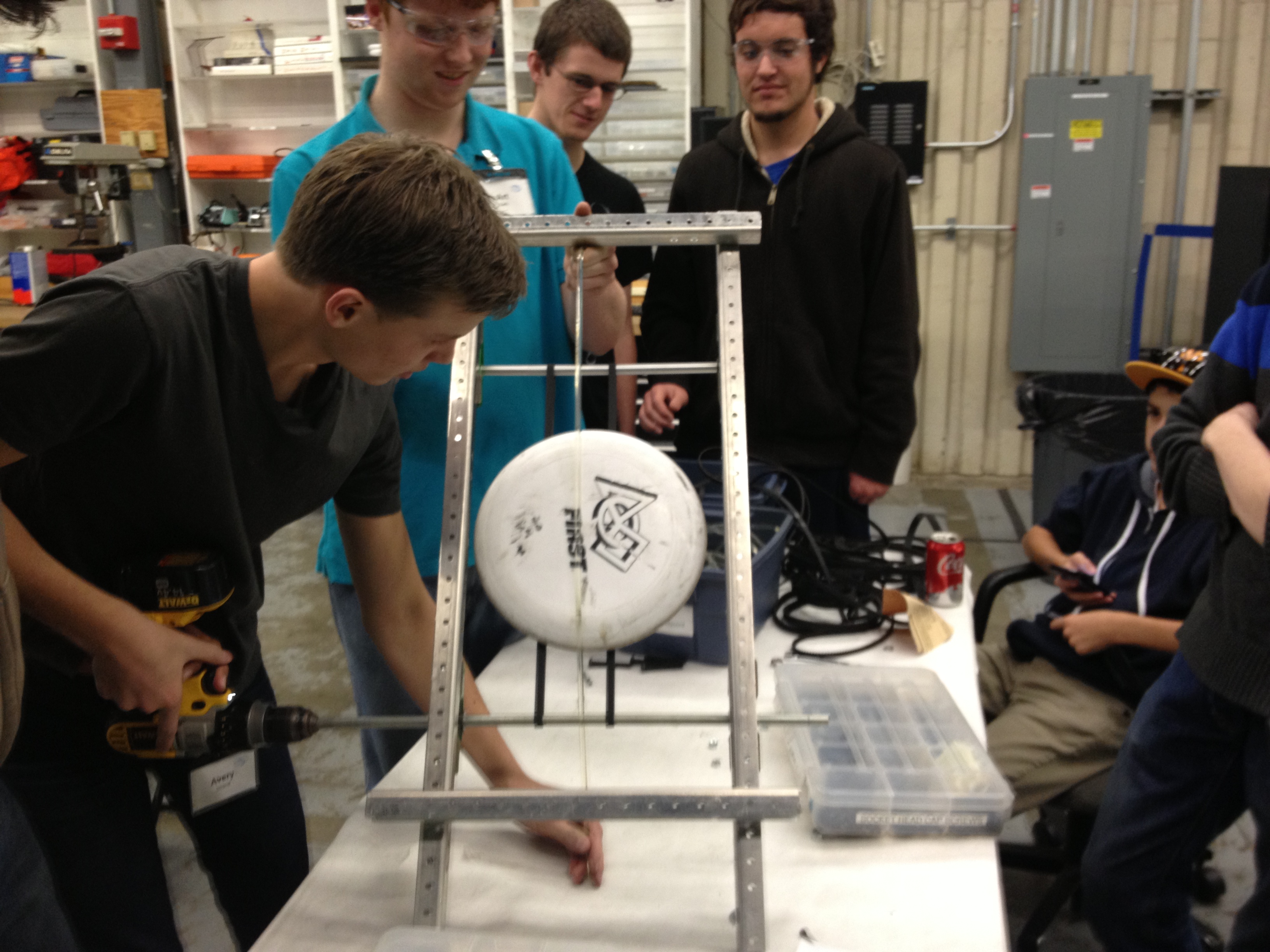
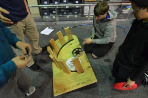
Students have made a couple of modifications to the shooter prototype. An L channel was added, in addition to guide rails. A pneumatic piston was attached to the shooter to load the frisbees into the shooter wheels.
The goal was to make a shooter that could shoot frisbees both upside down and right side up. After making the modifications and adding the "autoloader" the shots became more consistent (because of the same loading dynamics). However, the upside down shots and the right side up shots were aiming differently. The most significant difference is the flying dynamics. The upside down frisbees were more unpredictable and didn't fly as well.
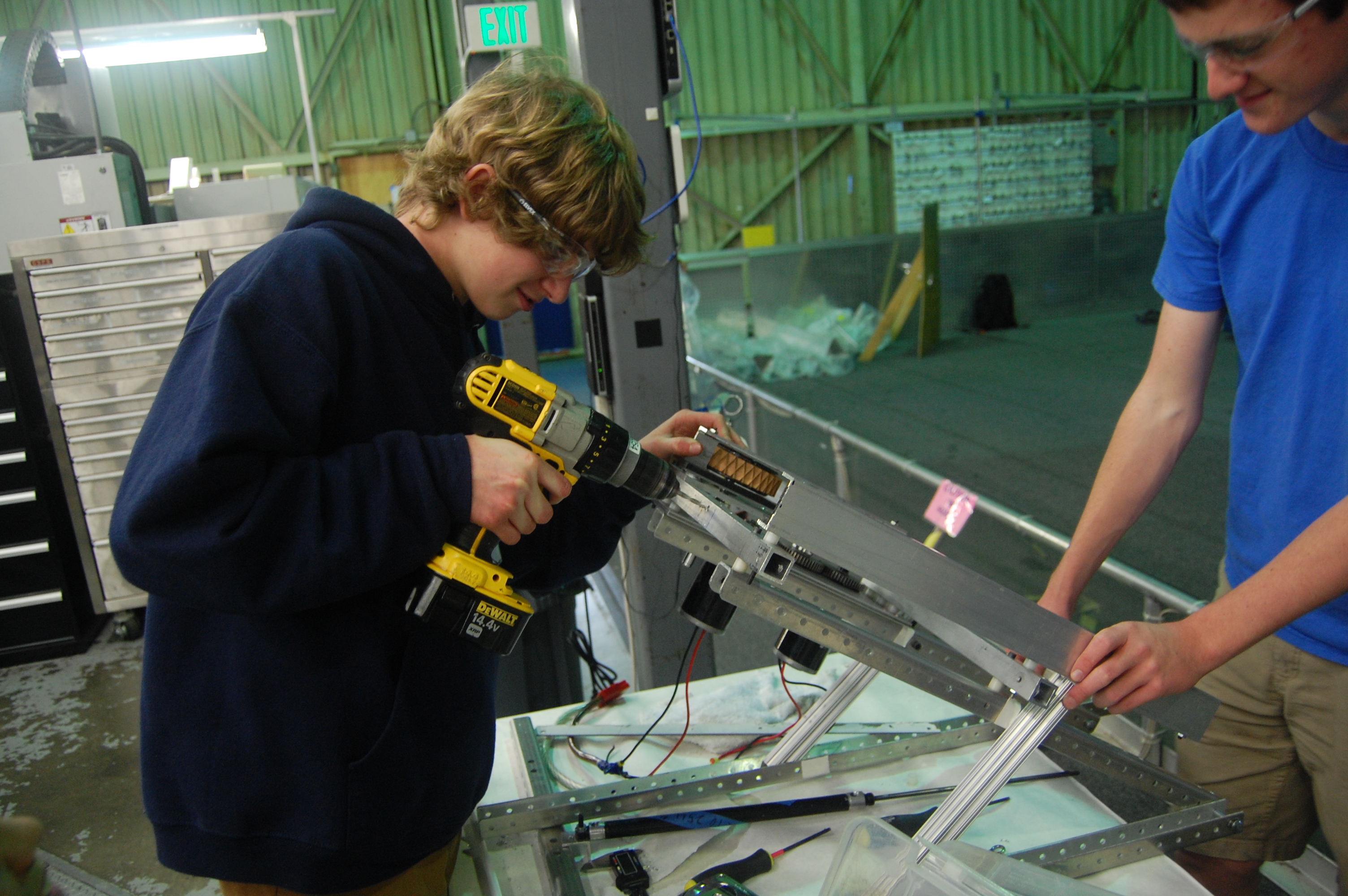
Students making enhancements to the shooter
Conveyor
Not much was changed on the conveyor. Upon the completion of the shooter and intake, students will integrate the conveyor design with the two other prototypes.
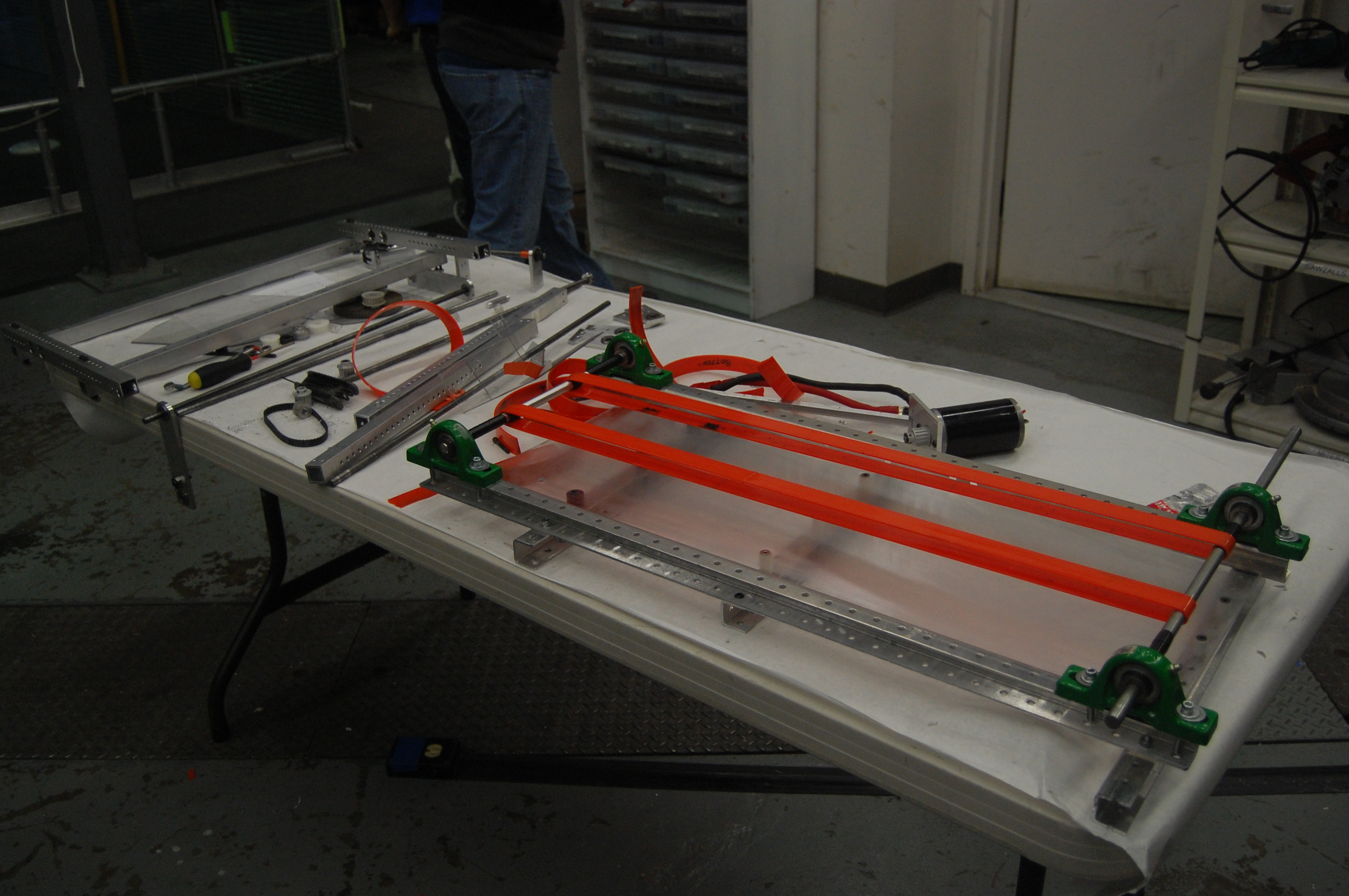
Conveyor prototype
New Intake
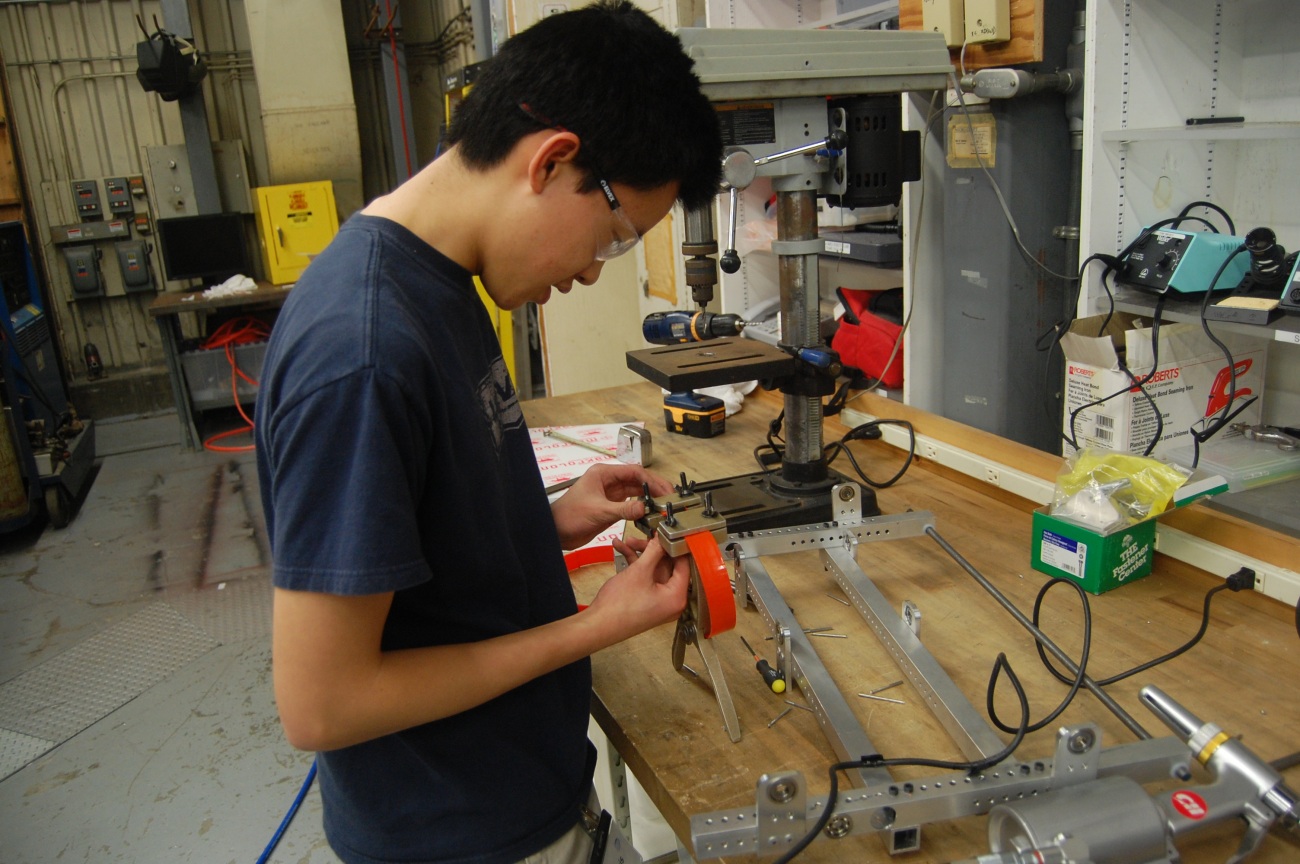
The team took a new route with the design of the intake. They removed some of the orange polyurathane belts in the process. A new intake was constructed from the CAD. Though it works fairly well, the team is working on improving it. It can't quite take two frisbees at the same, but can still pick them up quickly. The design is based on the old conveyor prototype and old intake prototype.
At the end of the night, the intake was fully functional and was able to funnel two frisbees into one. It was also able to easily pick up the frisbee from the ground, albeit not as well as was hoped. The intake so far is not fast enough and not consistent enough. More work will be done on it tomorrow.
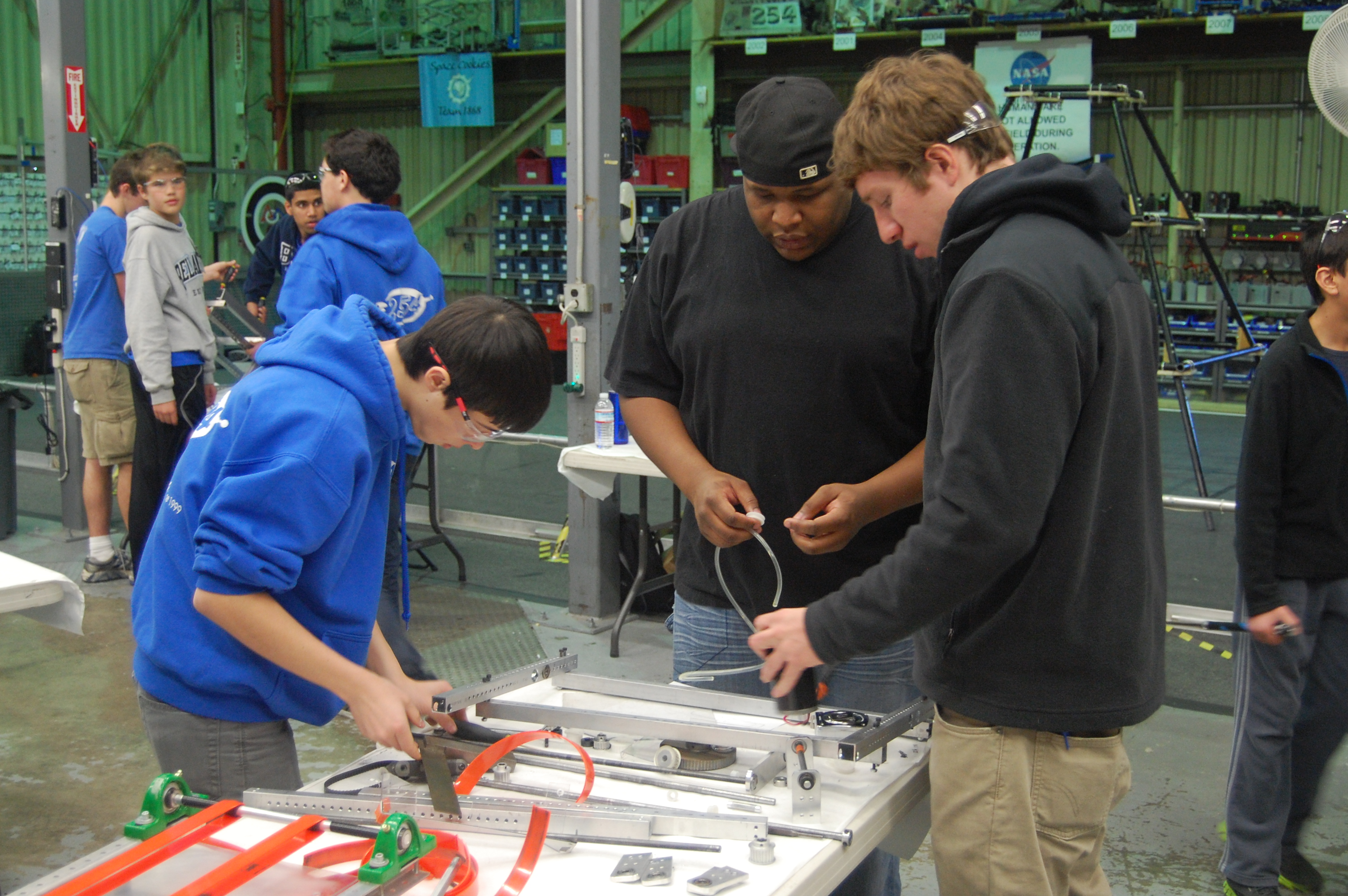
Building the new intake
Programming
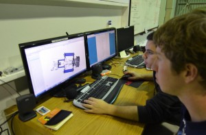
The programmers worked on a Smart Dashboard widget for writing constants and their values to a text file, and uploading them to the robot using FTP. They first worked on the layout of the widget, and were successful in the writing and clearing functionalities. However, the programmers still had issues creating an FTPClient object and connecting to the robot.
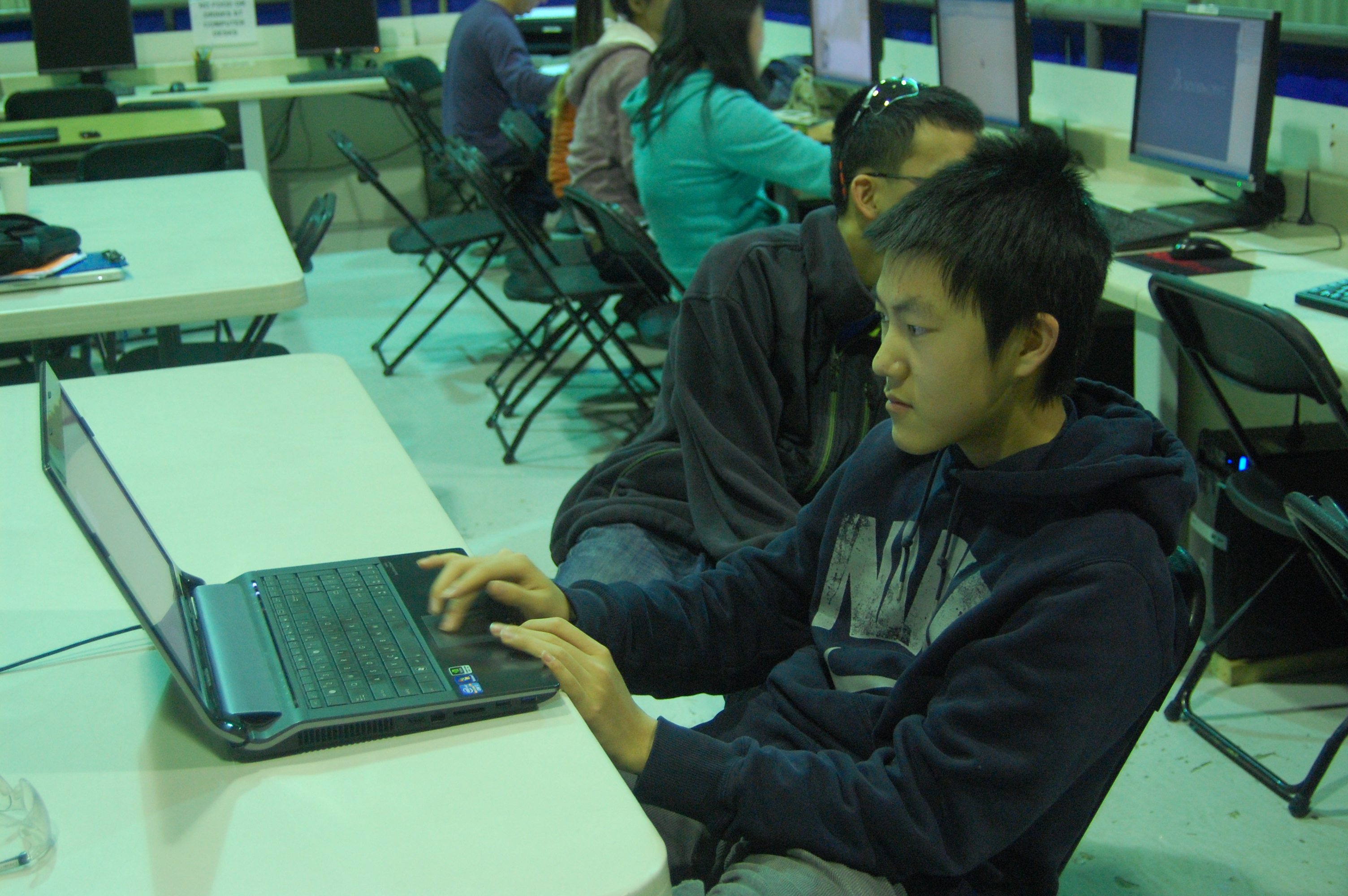
Dorian Chan programming the Smart Dashboard widget
Students also wrote a Turn Command for use during autonomous mode. The ScriptedAutoReader was configured to read the word "TURN" as a TurnCommand and appropriately create one. It seems to work, but the command still requires extensive testing, since the command depends on the gyroscope and the robot was left on the stand.
Richard demonstrating turning in real life
Miscellaneous
The pyramid was fixed. The top goal of the pyramid was brought down for some adjustments, and then reattached.
Fixing the pyramid goal
Action Items
-
Continue work on intake (make it work)
-
Make shooter accurate
-
Do math, save world
Lab closing time for the night was 2:00 AM
Build Season Begins
 The team is now a week into the short 6 week FIRST Robotics build season. We've made a ton of progress on everything from design and prototyping to field construction and programming. We have built the pyramid from the field drawings and have come up with a ton of concepts for various game challenges, some of which have been tested. The programming team has been working to get old robots up and running both for programming practice and for testing prototypes.

The team is in agreement that Ultimate Ascent, this year's FIRST challenge, is one of the harder games in recent FIRST history. However, we're happy with the prototypes that we've been working on and are confident that we'll be able to pull together a robot to play the game.
Team 254 works on a different schedule than many other FRC teams, designing and manufacturing parts in parallel. This forces us to design sequentially and finalize parts as soon as they are ready so they can be made in time. For example, some robot parts were designed on day two and sent out to sponsors on day three of the build season.
 As we move into week two, the focus is on continuing to prototype designs and trying to lock down some aspects of the robot design so that we can send more parts out to sponsors by the beginning of week three. It'll be busy but we think we can do it.
Day #8: Really Consistent Shooter Prototype
Prototyping
Intake Prototype
The intake was totally redesigned in Solidworks today. The design features multiple sets of belts to move the frisbees around. It uses belts on the bottom to increase the friction between the disc and the polycarbonate sheet. In total, 11 belts need to be manufactured and welded. The newly designed intake prototype is currently under development.
The conveyor prototype
Welding the polyurathane belts for the new intake
Making modifications to the intake roller
Shooter Prototype
Students made changes and modifications to the shooter prototype. C-channels were added on the left and right side of the prototype to guide the frisbee as it travels through the shooter's wheels, preventing it from moving upwards and adding stability. In addition, new parts and attachments for the shooter were milled and manufactured.
The shooter prototype
The shooting prototype was tested extensively. As the results show, the frisbees that were fired were somewhat accurate. The orientation of the frisbee (upside-down vs. right-side-up) appears to have a slight influence on the trajectory of the frisbee. An upside-down frisbee ends up at a smaller height than the height of a right-side-up frisbee.
2010 Robot
Makeshift bumpers were added to the 2010 robot today. The bumpers were constructed out of pool noodles, which the students will use to create the real bumpers from later on. The team hopes to use the 2010 robot's drivebase to attach and test the intake and shooter prototypes upon their completion. Metal frames were also installed on the robot. With these bumpers, students can test the intake mechanism as if it were on the real robot.
The 2010 robot with bumpers and metal attachments
Programming
The programmers worked on a multitude of tasks today. Some students worked on a custom Smart Dashboard widget that would populate a text file with a constant's name and value, then upload the file to the robot with FTP. Currently, the widget is working, but students still have to investigate problems with the FTP connection.
Students also worked on automous command scripting. With this, the robot can read autonomous commands from a text file on the robot, and execute them. The benefit of this method is that the team won't have to re-compile or re-deploy the code in order to make one small modification to the autonomous. Currently, the system is working as intended. The robot was able to interpret the drive and wait commands.
Lastly, the programmers continued to work on reading constants from a file. This has not yet been completed, but the students have a general idea and framework for what needs to be written.
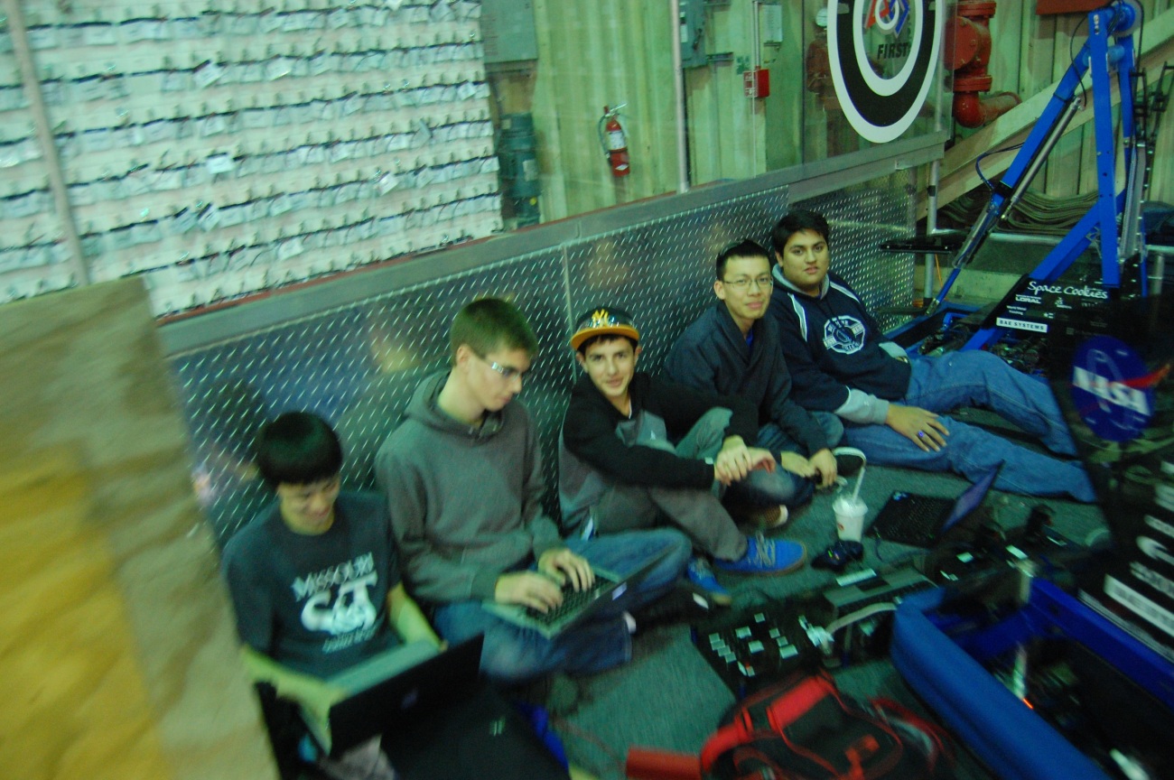
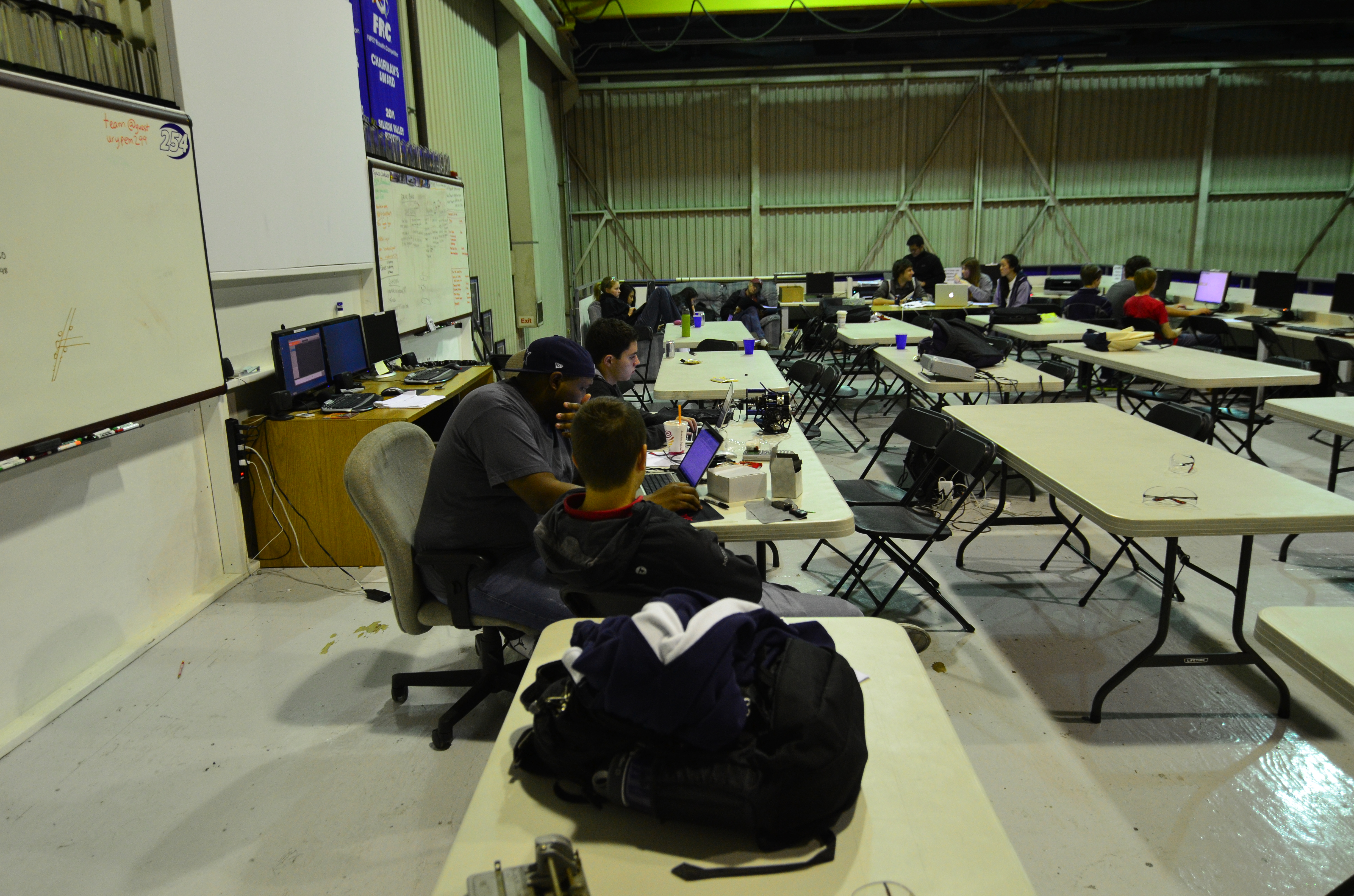
Programmers programming
Pat Fairbank
This is a prime example of our foremost Canadian mentor in his natural state of observation and intense thought about the world of robots.
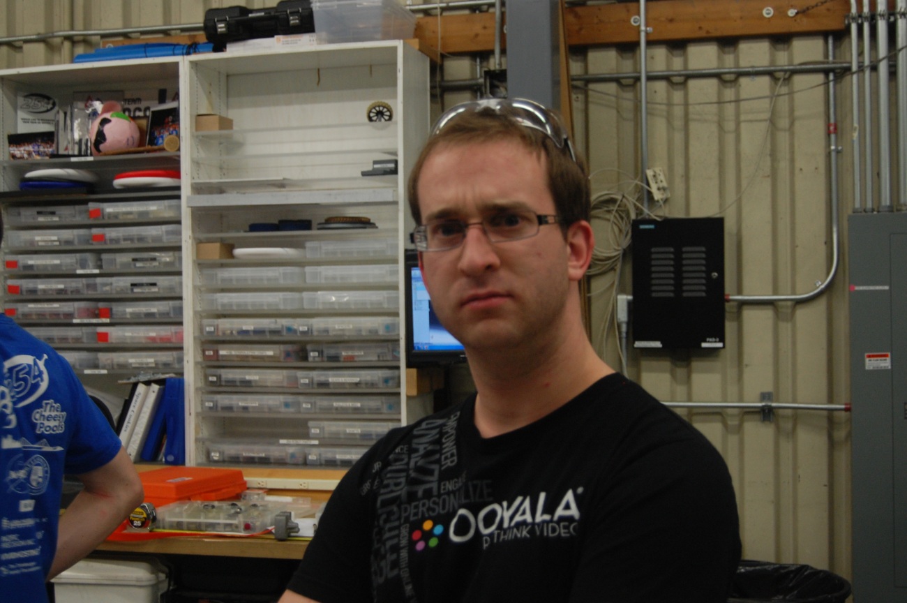
Pat being Pat
Action Items
-
Finish intake prototype
-
Mount said prototype to 2010 robot(onslaught)
-
connect all 3 prototypes and test from start to finish(Intake-Conveyor-Shooter)
-
Programming-work on reading constants from a file
Lab closing time was 12:50 A.M.
Day #7: Drive Base and Talon Testing
Prototyping
Intake prototype
Students continued to improve on the Intake prototype. We wanted to have the Intake prototype powered by one CIM motor. We designed a system which utilized timing belts, gears, and an intermediate roller to power both the top and bottom rollers of the Intake. This is currently still a work in progress
Intermediate conveyor prototype
The team continued to refine the conveyer prototype. The team started out by opening up the new polyurathane belts that came today, and proceeded to brainstorm on how they could improve the conveyer. The team decided on three things.
- Improved belts
- A Compression device to hold the frisbees in
- Counter Sunken Screws in said compression device
Improved Belts
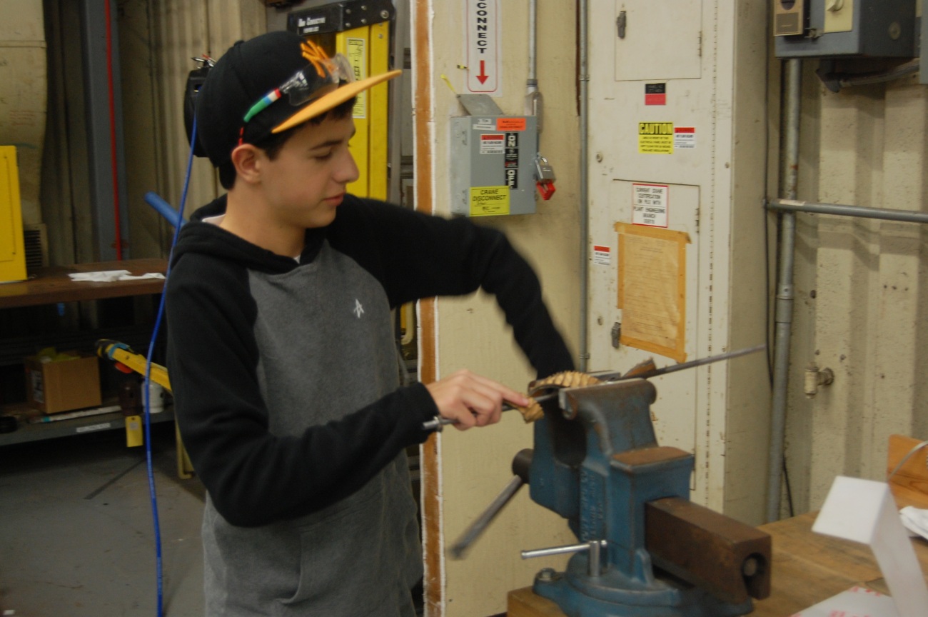
The old system continued to have slippage with the timing belts, and thought the new polyurathane belts would solve this issue. The team cut the belts to the correct length, fused them together, and stretched them over the place where the old belts were.
Compression Device
The compression device solved the issue of the frisbee slipping off of the belts. The compression device consists of a piece of polycarb which has been sanded down for reduced friction. The polycarb is drilled down 1.3 inches above where the frisbee sits, holding it to the belts
Counter Sunken Screws
The new compression device posed a new problem, screws sticking out of it, holding the frisbee back from free movement. The team solved this issue by using a technique called countersinking, where a divet is drilled around the area of the screw, allowing it to rest out of harms way. This completely solved the issue of the frisbee getting stuck.
Shooter prototype
- The 1×2 tubing was replaced with 1×1 tubing in order to raise the wheels higher so that they would contact the disc in an upside down orientation.
- The length of the bottom plate was increased to increase consistency when loading the disc
- The left side wall was shortened to try and make the discs go straight instead of off to the right.
- The stand for the shooter was improved such that it sits flat without being held down.
- Shooting upside down was very inaccurate because even with raised wheels, the wheels still push the disc up. U-channel needs to be added on both sides to keep the disc in line.
- With the shortened left side wall, the discs did not fly straight, they flew to the right. With U-channel added on both sides, and past the wheels, the discs should fly straight as they exit the shooter.
Programming
Then programmers updated the 8-wheel 2010 drive base to work with Talons. It will be used to mount the prototype intake and shooter. The team also made the robot controllable with the Logitech gamepad. A few members and mentors drove the robot around the field with the new controller. There is no new progress on the constant file reading system nor the autonomous command system.
Tomorrow, the programmers will work on the autonomous command system, the gamepad controls, and constant file reading.
Lab closing time was 12:30 AM
Day #6: Consistent Shooting Prototype
Design
Gearbox Design
It was decided that a power take-off (PTO) mechanism will be implemented into our drivebase gearbox design. A power take off simply allows all the power from the drivebase gearbox to be applied somewhere else. This is achieved by adding an extra output shaft to the gearbox with a another shifter, giving the gearbox 3 "speeds". There is the high speed, low speed, and "neutral" speed. Neutral will inhibit the wheels from receiving power and allow our hanging mechanism to be fully powered by six CIM motors (the most powerful motors in the Kit of Parts).
Implementing the PTO will give the hanging mechanism the maximum amount of power (since the motors allowed are limited) thus allowing the robot to hang as quickly as possible.
Today's progress included adding a third CIM motor to the gearbox and changing the configuration of the motors to allow for a second shifter and second output shaft.
This gearbox will be the biggest, heaviest, and most powerful gearbox Team 254 has ever built! It will be called "Big Daddy!" to compliment 2011's enormous intake gearbox, which was crowned "Big Momma"
Prototyping
Intermediate conveyor prototype
Students worked on prototyping an intermediate conveyor system which will be used to transfer the frisbees from the intake to a second mechanism which will transfer the frisbees to the shooter. The second mechanism has not been prototyped as of now. This prototype currently uses timing belts that are connected to two horizontal rollers. These rollers are currently running at 1400 rotations per minute. As of now the prototype works as long as it is tilted less than thirty degrees from the ground. When the prototype is angled more than thirty degrees from the ground, a pressure must be exerted perpendicular to the rollers for it to work.
Shooter Prototype
The shooter prototype was repeatedly tested, and it fires consistently when the frisbees are right side up. However the consistency is lost when the frisbees are placed upside down. As of now, we would like to add something that would prevent the frisbee from angling upwards before it exits the shooter.

Intake prototype
Students added bearings to the rollers in the prototype to prevent the loud clacking noise that occurs when it is operated.
Miscellaneous
Students finished the CAD for the LED Power Box and components. This will be assembled later and used for the pit area trussing.
Students built a mock-up human player station. They also determined best way to feed frisbees through the human player station and throw them across the field during the last thirty seconds of a match
Programming
With a new to-do list to keep track of action items, a multitude of programming-related tasks were completed or started. Students worked on getting constant variables to read from a file for the robot code. This updating would happen in robotInit(), right as the robot turns on. They also worked on reading autonomous scripts from a file for the robot in such a manner that these scripts deployable without re-compiling. Since they don't have the actual autonomous functions yet, programmers have created an initial structure to parse in names of the commands and their parameter(s) from a text file. The Smart Dashboard was installed on the driver station. Tomorrow, programmers will work on creating custom widgets to place on the dashboard. Lastly, programmers imported math functions from the 2012 robot code into the 2013 robot code.
Action Items For Tomorrow:
-
Upgrade Intermediate Conveyor Prototype
-
Upgrade Shooter Prototype
-
Continue Programming (See Richard's Action Item List)
-
Finish Drivebase CAD
Time Left the Lab: 12:00 AM
Day #5: Continued Prototyping
Today was a very productive day at the lab. There was a lot of progress made in many areas.
Prototyping
Shooter Prototype
Improvements were made to the shooter prototype. After students replaced a faulty CIM motor, an adjustable base was added to the linear shooter to allow testing at multiple angles. This base will help optimize the perfect angle for shooting a frisbee. The base was constructed out of kitbot parts and 80-20 extrusion.
Richard assisting students with the adjustable shooter platform assembly
Intake Prototype
Students worked on improving the roller-intake prototype by testing different kinds of tread spinning at different speeds. It was found (unsurprisingly) that the roller must be spinning very quickly (about 2,000 RPM) to intake the frisbee. Long rough-top tread attached as "fingers" did not work well. A piece of rough-top tread that was wrapped around the roller worked the best.
After determining this improved treading configuration, students and mentors worked on setting up the prototype as an over-the-bumper intake. Rather than sucking-in the frisbee horizontally, tests were conducted to see if the frisbee could make a smooth and easy transition from a horizontal position on the ground to an angled position over the bumper.
Updated Intake prototype
Restoring the 2010 drivebase
Students continued to attempt to restore the 2010 drive base, in order to attach prototypes and drive around. After an hour of debugging, it was concluded that a faulty cRIO was on the robot. The efforts were abandoned because of a lack of replacement cRIO. Hopefully, a new cRIO is acquired soon in order to continue testing.
Restoring the drivebase was also supposed to be an excercise for the new programmers, so they could practice writing brand new code and uploading it to a functioning robot.
Programming
Tom dropped some knowledge bombs on the programmers today.
Constants
Students continued to brainstorm and discuss possible ways of updating values without having to re-compile or re-deploy the code. Some ideas that was brought up was having a text file for each constant, or having an "isModified" boolean value somewhere.
Action Item List
An action item specific to programming was created yesterday. This is essentially a to-do list, which organizes and tracks tasks what need to be completed and the priorities of tasks. This list should make it easier for students at the lab to more easily contribute to programming effort.
Miscellaneous
Light Control Box
Two students worked on modeling a project box and the components to go inside it. This project box will house a power supply and will be the control box for the lights hanging on the trussing in the pit area.
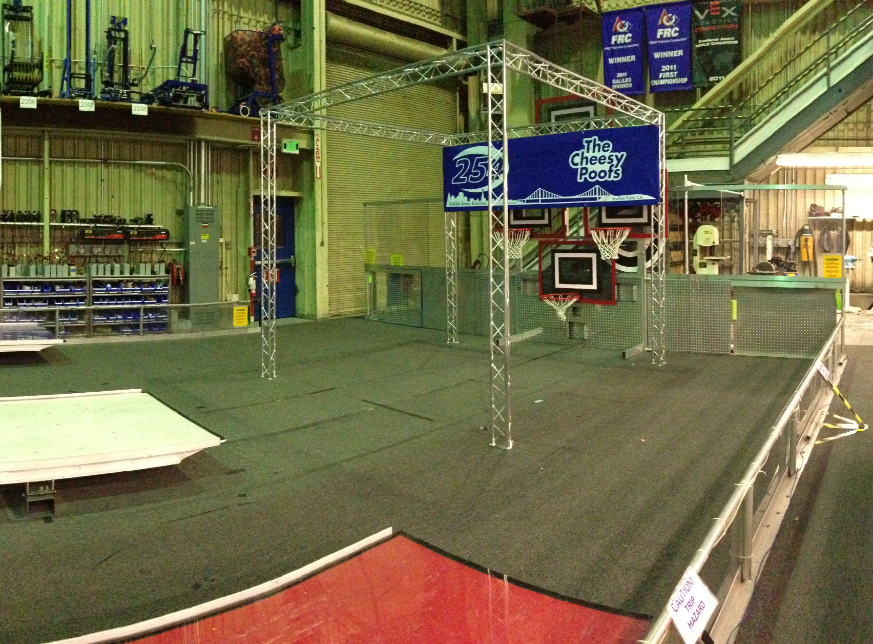
Pit Area trussing for banners, lighting, and monitor mounting
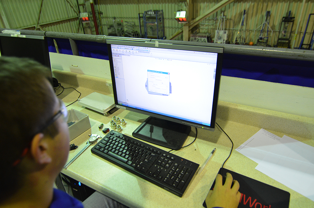
A student modeling the project box in SolidWorks.
Action Items for Tomorrow
-
Fix the wiring to the cRIO on the 2010 robot; flash new image to cRIO
-
Work on and test prototype for intake
-
Work on and test linear shooter prototype
-
Complete drivetrain design. Deadline is Friday.
Lab closing time was 11:00 pm
FRC Programming – Action Items
In order to keep track of programming-related action items for FRC, we've created a spreadsheet with tasks that are sorted by priority. If you're ever at the lab and want to do some programming, swing by and choose a task that interests you. We hope that this list will make it easier for you to find a cool project to work on while in the lab.
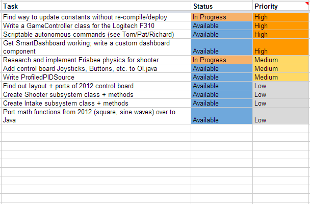
The action item list, as of Day 5
As always, you can let Richard, Stephen, Tom, or Pat if you have any questions or need clarification. Be sure to read the blog often to check out our programming progress!
Day #4: Success with Intake and Shooter!
Today was a huge improvement in student attendance over yesterday. With our first active weekday build, a majority of the time was spent designing and beginning initial prototyping of an intake mechanism.
Prototyping
Intake Prototype
Students worked in a group to brainstorm ideas for an intake mechanism that will allow the robot to take in discs from the ground. One of the several ideas brought up include horizontal rollers to roll the discs in. However, the orientation of the disc (facing upwards or downwards) and friction between the carpet and the disc are challenges. Currently, one new intake prototype has been constructed that can take in discs on the ground from either orientation.
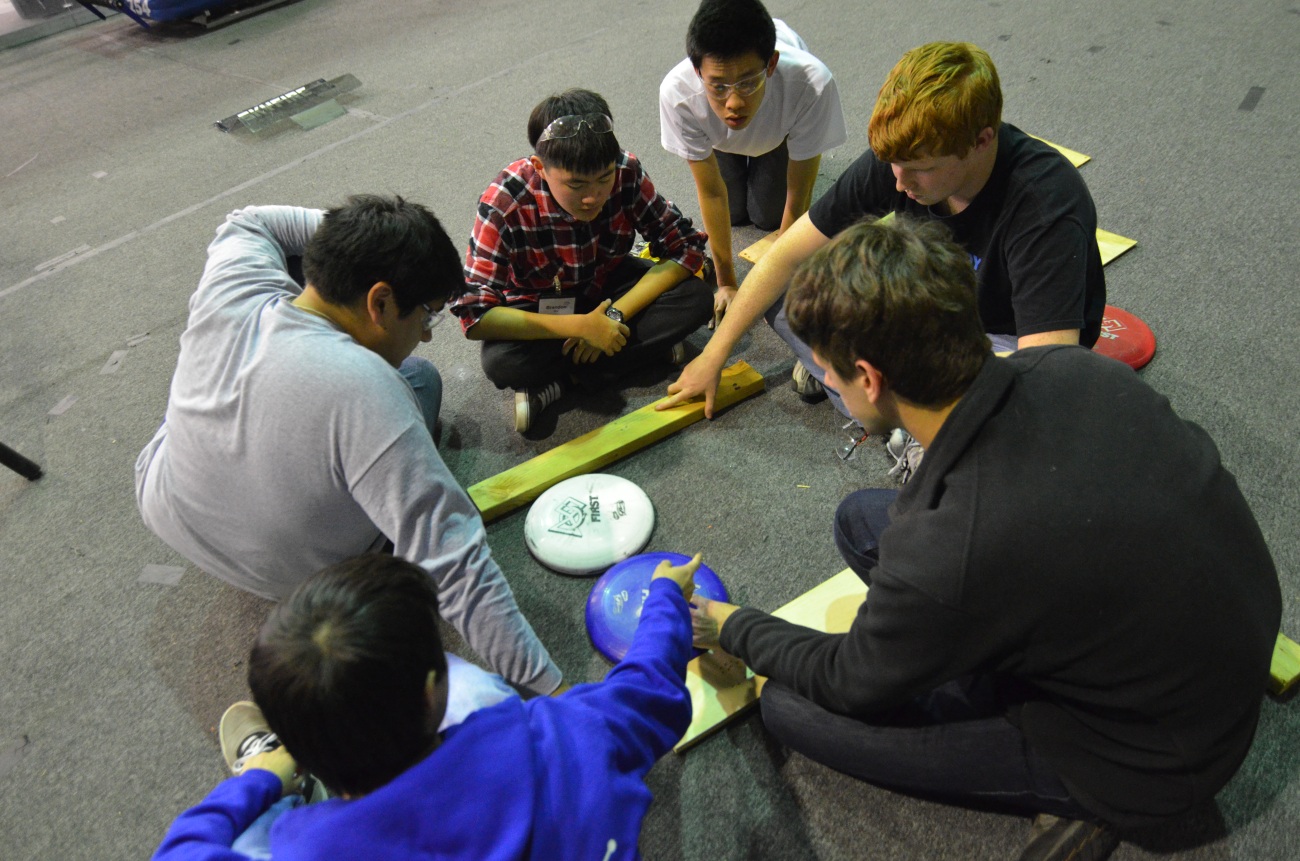
Students brainstorming ideas for the intake
Shooter Prototype
Additionally, some students are continuing work on manufacturing parts for shooter prototypes.
One new shooter prototype that is under construction is a linear shooter, powered by two wheels. One wheel will be powered such that it is faster than the other.
Manufacturing parts to build a shooter prototype
Testing Prototypes
Some students are using the drivebase of the 2010 robot, Onslaught, in order to test shooting and future intake prototypes. Currently, there is a problem with power to the cRIO, which prevents controlling or deploying code to the robot. Once the 2010 robot is up and running, the team will attach prototypes to the robot to test out prototypes on the field, while driving.

Drivebase of the 2010 robot, Onslaught
Programming
Reading Constants
The programmers discovered that original idea to use Java reflection will not work because the robot uses Java ME (mobile edition), which does not support this feature. They brainstormed some other possible solutions including using a hash map for storing variables read from a file, but it is likely unfeasible due to its heavy computational expense. Another idea is to use a flat text file with constant values that can be transferred to the robot without re-compiling and re-deploying code.
Controls
In addition, the programming team tested out a Logitech game controller as a way of driving the robot. The analog sticks on the controller were successfully used to control the drive. More comparisons and tests between joysticks and the game controller will occur later on in the season.
Action Items for Tomorrow
-
Fix the wiring to the cRIO on the 2010 robot; flash new image to cRIO
-
Work on and test prototype for intake
-
Work on and test linear shooter prototype
Lab closing time for the night was 12:30am
Part Management System
To help manage the robot parts in CAD and their manufacturing status, there is a new web-based part management system located at parts.team254.com. This system assigns official part numbers, stores information about parts and the materials required to make them, and shows the current manufacturing status of each part.
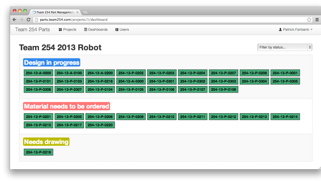 Parts currently in the manufacturing pipeline
Build Season Recipes: Week 0
I received a couple of requests for the cookie recipe from Kickoff weekend, so I'll just post it here on the build blog. Stay tuned for future weekly deliciousness and nutritiousness!
Double Chocolate Cookies
-
1 cup butter
-
1 cup sugar
-
1/2 cup brown sugar
-
1 tsp. vanilla extract
-
1 egg
-
1/3 cup cocoa powder
-
2 tbsp. milk
-
1 3/4 cups flour
-
3/4 tsp. baking soda
-
3/4 cup chocolate chips
Cream butter, sugars and vanilla extract. Add egg, milk and cocoa; beat. Add flour and baking soda and mix just until blended. Stir in chocolate chips. Drop on cookie sheet and bake at 350°F for 12 minutes.
Day #3: Design Discussion
Today was the first weekday of build and with fewer member attendances, there was a lot of individual work getting done. Majority of time was spent in conversation between students and mentors on design decisions.
Prototyping
Three different designs are continuing to be prototyped:
- Arm design
- Started installing a longer piston
- Increase range of motion to have greater spin
- Extended arm length
- Linear Design
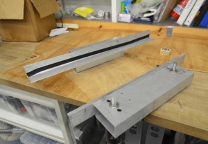
- Wood bottom plate removed because of warping
- Bottom plate replaced with metal bars to reduce bend
- Added electrical tape to increase traction
- Adjustments made to effectively improve consistency
- Radius design
- No work was done on the radius design today
Design
Mentors and students continued designing the robot baseplate and the drivebase in Solidworks. The drivebase was completed before Nagy lost all his work. It will be completed tomorrow at school.
New discussion outcomes:
- 32″ x 24″ frame
Additional testing
Students began to install 4 new Talon speed controllers on the 2012 robot Skyfire drive motors to replace the Victor speed controllers. Later on, the Talons will be tested and then based on results, the team can decide which speed controller to use for competition.
Programming
The programming team worked on implementing a trapezoidal motion profile to accompany PID control, which involved quite a bit of math. Meanwhile, other programmers continued working on a way to read constants’ values from a text file, and update the constants accordingly. Tomorrow, we hope to make adjustments to the code to use Talons instead of Victors, and test drive the 2012 robot.
Action Items for Tomorrow:
- Finish drivebase CAD (restore Nagy’s lost work)
- Continue Prototyping
- Add support for Talon speed controllers in code, test, and compare with Victor speed controllers
Lab closing time for the night was at 10:30pm
Day #2: Finished Pyramid!
Today the team got a great start as soon as we could access the lab, making substantial progress on a multitude of projects.
Prototyping
Today in prototyping the team pursued our 3 designs decided yesterday for shooting mechanisms which are:
-
Radius design
-
Continued to try and make shots using the pneumatic air wrench to
drive the flywheel
-
Used the strategy of touching the pyramid to take shots without being hit by opponent robots
-
Created a feeding device to automatically load frisbees into the shooter
-
-
Linear Design
-
CNC machined part of the belt mechanism to create a tensioned timing belt system to launch the frisbee
-
Added guide rails to create a solid static wall opposing the timing belt to create spin on the frisbee
-
Added flanges to the pulleys to help guide the timing belts
-
The pulleys are powered by a direct mounted CIM Motor running at 5300 RPM
-
Shows promising capabilities both in power and spin and is being pursued in greater depth
-

-
Arm Design
-
Completed initial prototype design
-
Mechanism is powered by a 1 stroke piston
-
Semi-effective at short range
-
Needs to be modified to increase range and spin to be able to get a better understanding of its capabilities
-

Design
The decision was made to build a modified version of the 2011 drive system which operated a 6 Wheel Drivetrain System with two speed gearboxes (high gear at 19.8fps, low gear at 7fps). Center wheels are lowered to allow for maximum maneuverability. 3.5″ wheels keep the robot center of gravity very low to the ground. Additional design improvements have been pushed to tomorrow for final decisions. The team is still in the process of brainstorming designs for both intake and climbing/hanging mechanisms.
The part drawings for the main shafts in our drivetrain are completed and ready to be sent out to sponsors. The completed drawings are for the following parts:
-
Drive Gearbox Output Shaft
-
Drive Gearbox Intermediate Shaft
-
Wheel Shaft Medium
-
Wheel Shaft Short
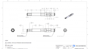
Output shaft drawing
Field Construction
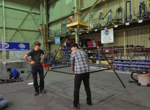
Students completed all components and assembly of the pyramid, creating a solid basis for hanging prototype testing.
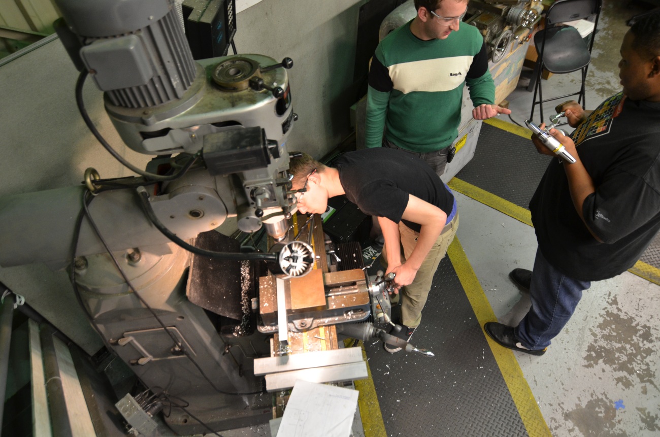
Machining
The CNC mill was used to mill components for the linear shooter prototype and is prepared to be in around-the-clock machining as soon as the preliminary metal shipment has arrived.
Programming
The programmers began to write some code in Java to deploy to the 2012 robot. They used the CommandBasedRobot structure for the code, and fixed all previous errors that popped up before during deployment. The code was deployed and ran successfully. Currently, the team has a completed drive subsystem and a couple drive commands. In addition, some students worked on a system to read values from a file for on-the-go constants editing.
Lab closing time for the night was at 1:00am
FRC Season Day #1: Kickoff
After the whole team kickoff-unveiling event at BCP, students came to the NASA lab at 1:00pm to begin discussing game strategy, going over the new game rules in detail, and began numerous design, prototyping and field assembly tasks throughout the course of the day. Prototyping A couple of groups were created which began making prototypes to test the fundamental concepts of shooting Frisbee discs. A few objective requirements that are being looked at in these designs include:
- Accuracy
- Precision
- Size/Volume occupied
- Power requirements
- Design integration ease
- Feeding/indexing/loading ease
- Need for adjustability
Three different designs are currently being prototyped:
Radius Design
- This design is very similar to this YouTube video
Radial Design
- The radial design uses a fixed wheel spinning on an axle surrounded by a circular track for a frisbee. By doing this there it simultaneously adds speed to the frisbee using the rotating wheel and spin using the far wall of the track that is padded with self-insulating electrical tape for increased grip.
- We used many different iterations of motors starting with Dewalt drills, but opted for more power using pneumatic drills running off shop air spinning the wheel at 5250 RPM.
- Using the higher RPM we were able to semi-accurately shoot from 10ft away from the high goal.
- A working prototype was created and tested today as shown in the video above
Linear Design
- This design is an iteration of the Radius design, but packaged more tightly to accelerate the Frisbee disc linearly, instead of around a radiused backboard
- The idea was created as a derivative of the Radius design, coming from the need for a compact shooting mechanism. Utilizing the same idea of a static surface combined with a spinning propellant, we designed a system that uses a direct mounted CIM motor to power a timing belt pulley system to increase speed of the frisbee in a single linear movement.
- CAD models of this design were completed and fabrication was started today
Thrower Arm Design
- This design is most similar to a clay pigeon device
- The main mechanism of this design is a flinging arm that propels the frisbee as it travels from the center of the device towards the outer most edge
- Fabrication of this design was started and photos will be added when a preliminary model is created
Design Preliminary design decisions were briefly discussed regarding drivetrain configuration, wheel size, and speeds/ratios. Final drivetrain decisions and preliminary designs for some drive components will be decided and completed at tomorrow’s meeting. Gearbox and wheel shaft models and drawings are scheduled to be completed by Sunday night, to deliver for manufacturing at our sponsor on Monday morning. Preliminary discussion outcomes:
- 6WD with 3.5″ Wheels
- 2-speed WCD (West Coast Drive)
- ~2011 speeds (with the capability to swap in a smaller pinion to go slower)
- Flat base plate
- 2011 style bumper mounts
Field Construction Students began working on building and assembling the high goal and the pyramid field objects. The High Goal stand was completed and mounted onto the game field. The assembly of the pyramid is underway, with its top goal almost complete; all components are made, but still need to be assembled together.  Manufacturing Final machine set-up and warm-up procedures were completed today which should allow us to start machining competiton parts tomorrow. Action Items for Tomorrow
- Acquire missing pyramid parts, assemble pyramid base and goal, assemble pyramid.
- Complete linear Frisbee shooter prototype & test
- Begin intake design and prototyping discussions
- Start and complete drivetrain gearbox designs and shaft drawings
- Discuss merits and perform objective analysis/ranking on hanging mechanisms & feasibility
Lab closing time for the night was at 12:30am
Team 254 Helps out at Toys for Tots
On Saturday December 22nd, 27 Cheesy Poofs came together to help needy children in the Santa Clara Valley. The members donated over 70 hours to help distribute gifts to the needy and bring smiles to their faces. The boys were painting faces and hands with Christmas scenes, running games with prizes, cooking hot dogs, distributing food and demoing Skyfire to the delight of all ages. This is the 25th Annual US Marines Toys for Tots event at the Fairgrounds and it was expected to reach 7,000-9,000 children.
