
Blog - January 2014
Day 6: Prototyping the Catcher, Building a New and Improved Flywheel, and Organizing Parts
by Jeffrey Kaufmann
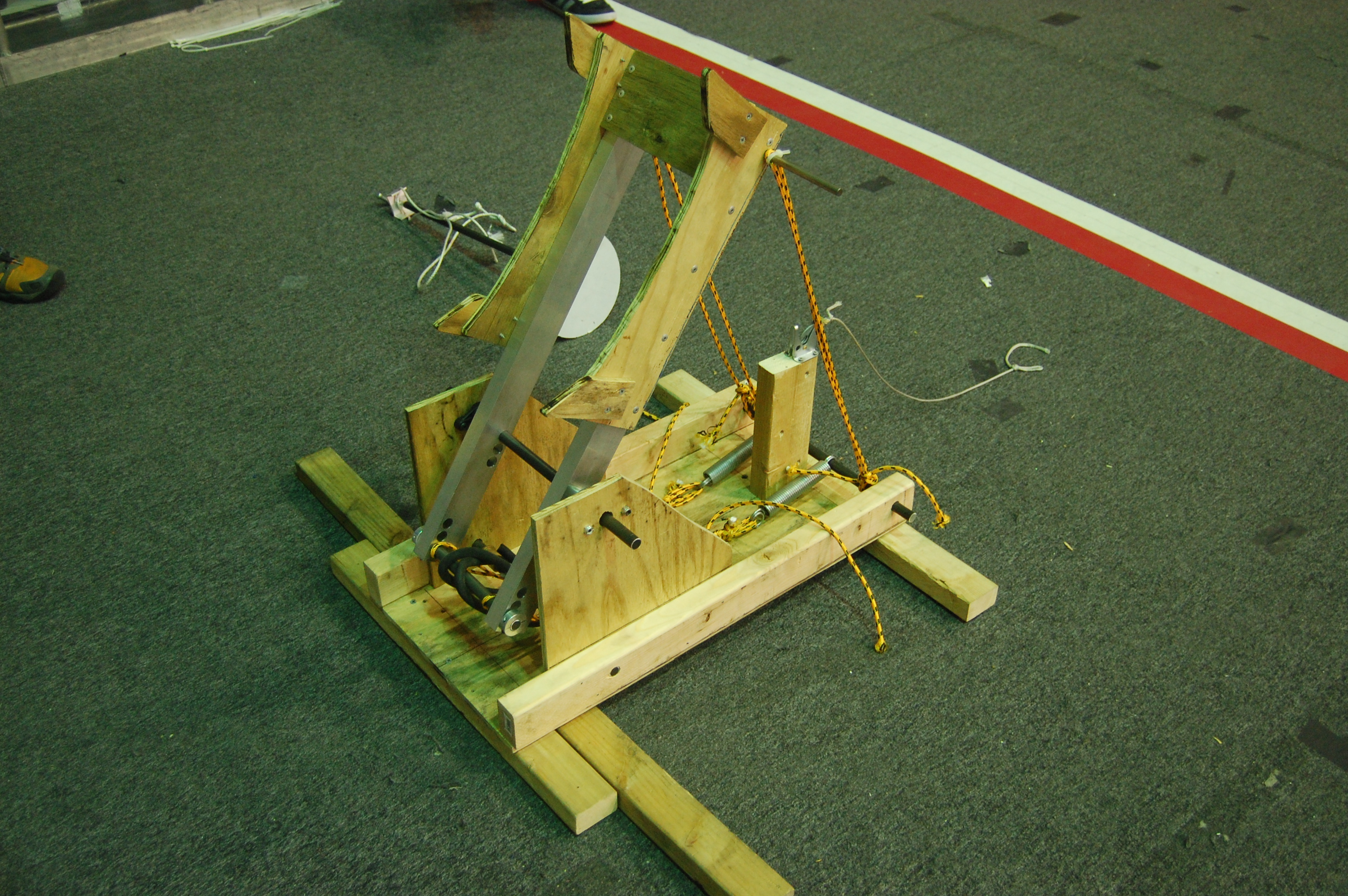
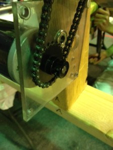
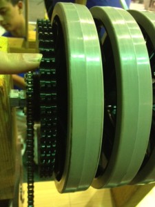
New Flywheel Prototype
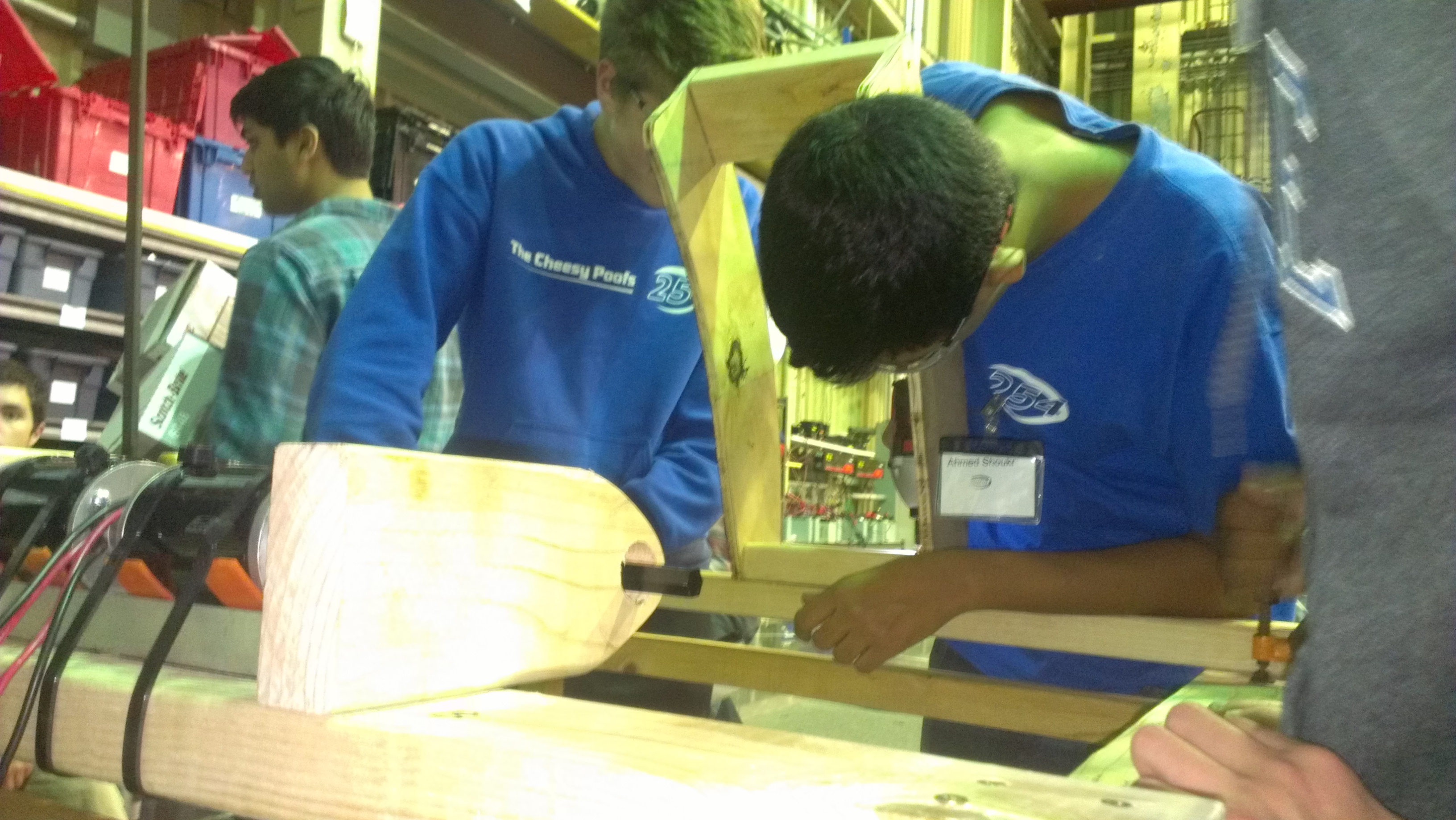
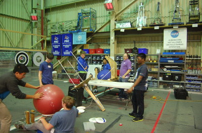
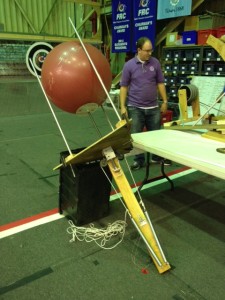
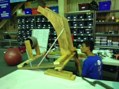
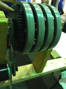
A team of students worked on the updated prototype of the flywheel shooter. The new prototype can shoot at an almost vertical angle, enabling the robot to toss the ball over the truss. It also allows for easier packing because its flywheel is smaller than that of the first prototype yet still retains the positives aspects of the original. Some problems occurred during the construction of the new wheel such as broken or splitting wood pieces delaying completion.
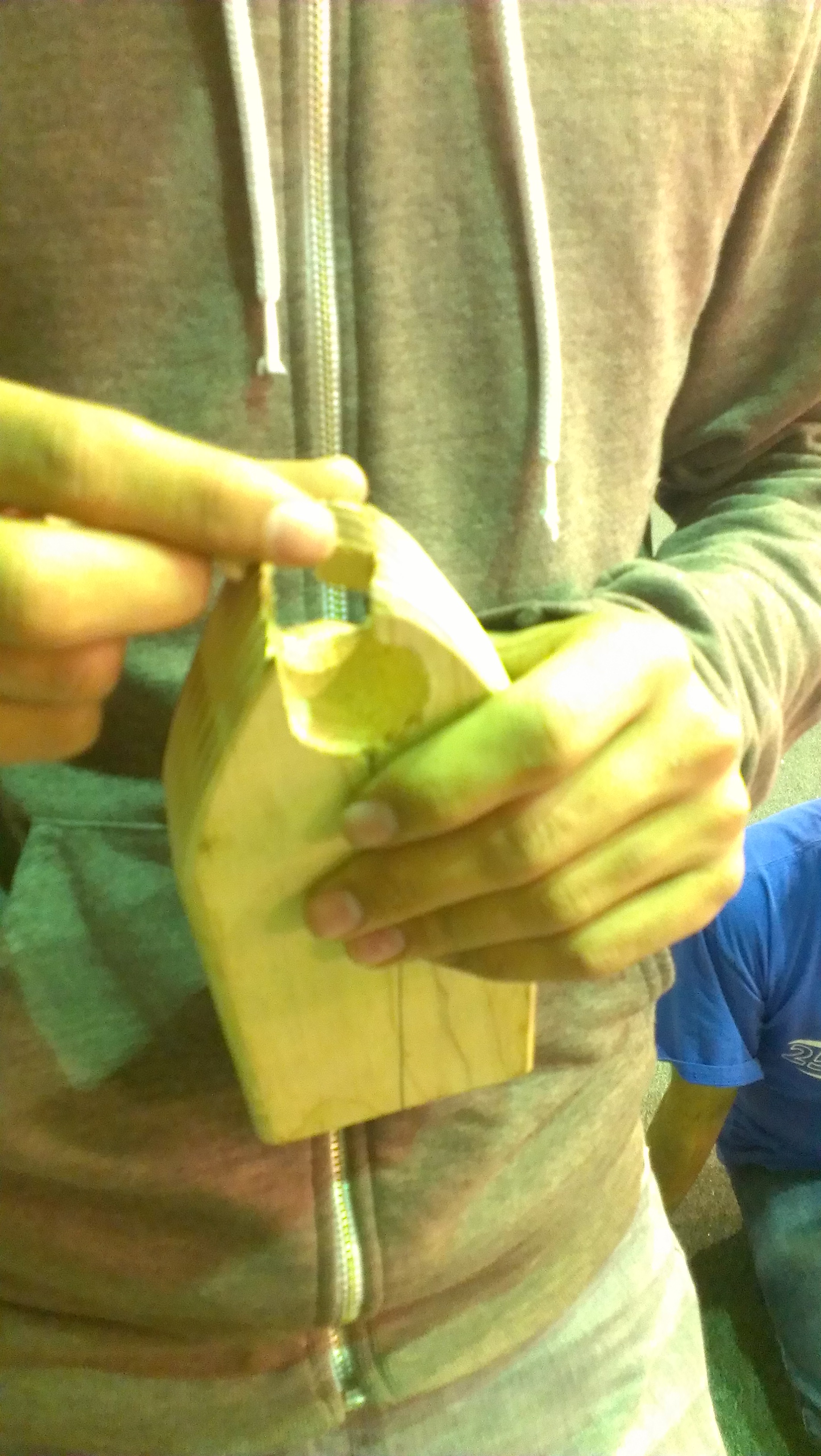
This piece had to be replaced. The team attached the curved piece of the flywheel that allows for an approximately 45 degree trajectory.
New Catcher Prototype
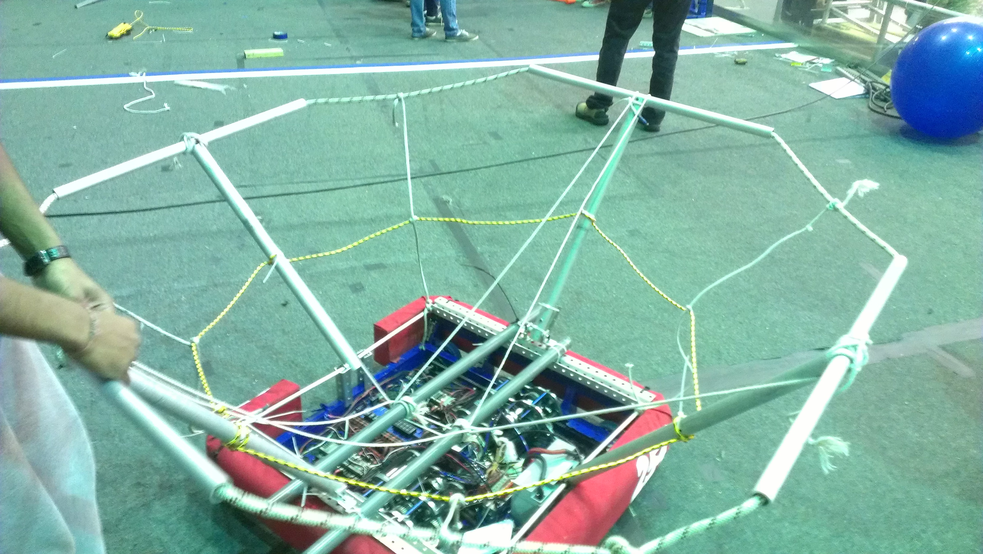
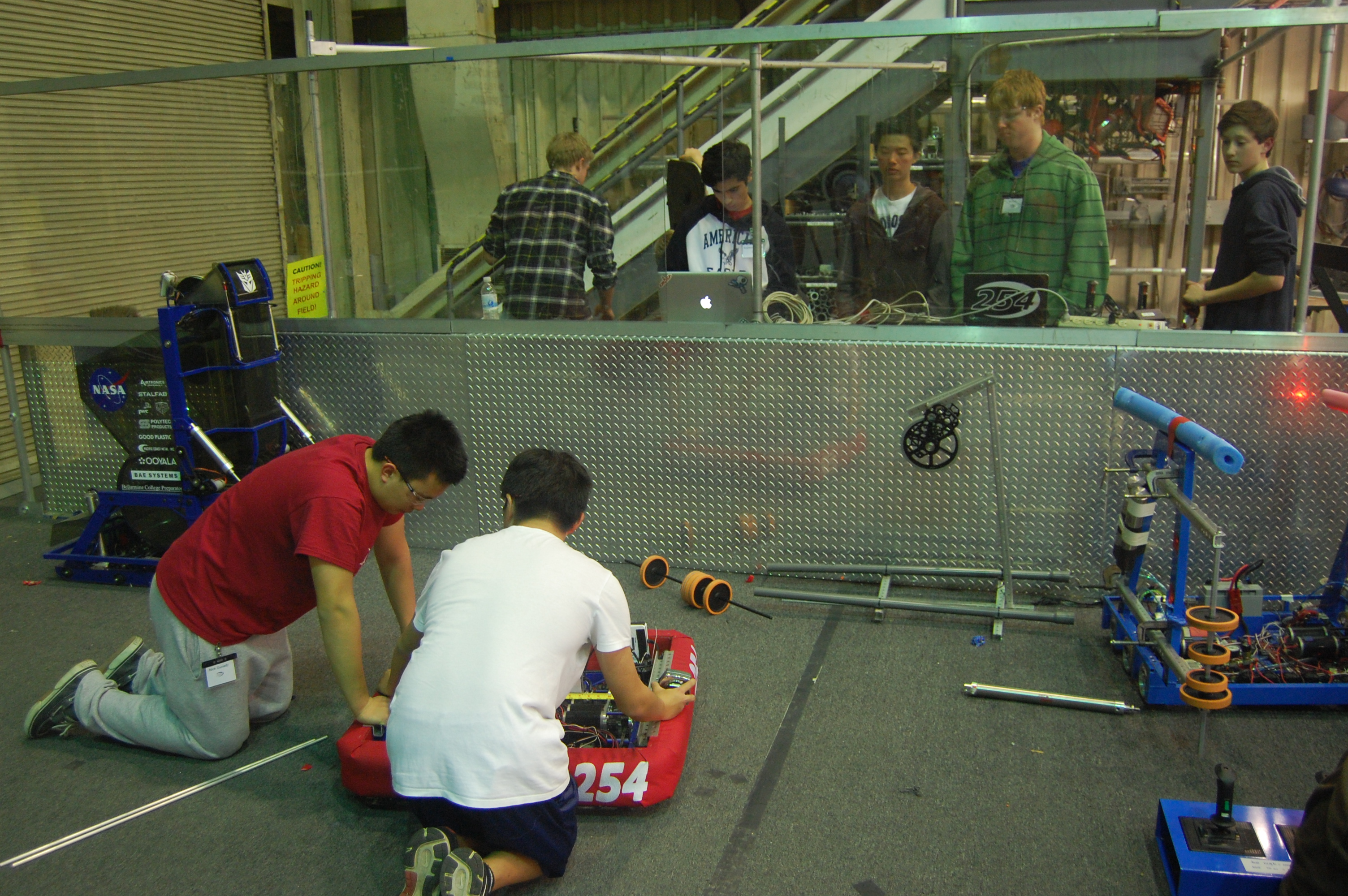
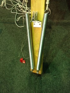
A group of students worked on fixing the second catcher prototype. This update will allow for a more mechanically robust device. The rope on the catcher and add a few metal pieces were overhauled today, resulting in a tighter, more stable and cleaner design.
After testing the new mechanism while driving the results were quite satisfactory. The great mobility of the drive granted the ability to quickly get underneath the ball and receive an almost perfect catch.
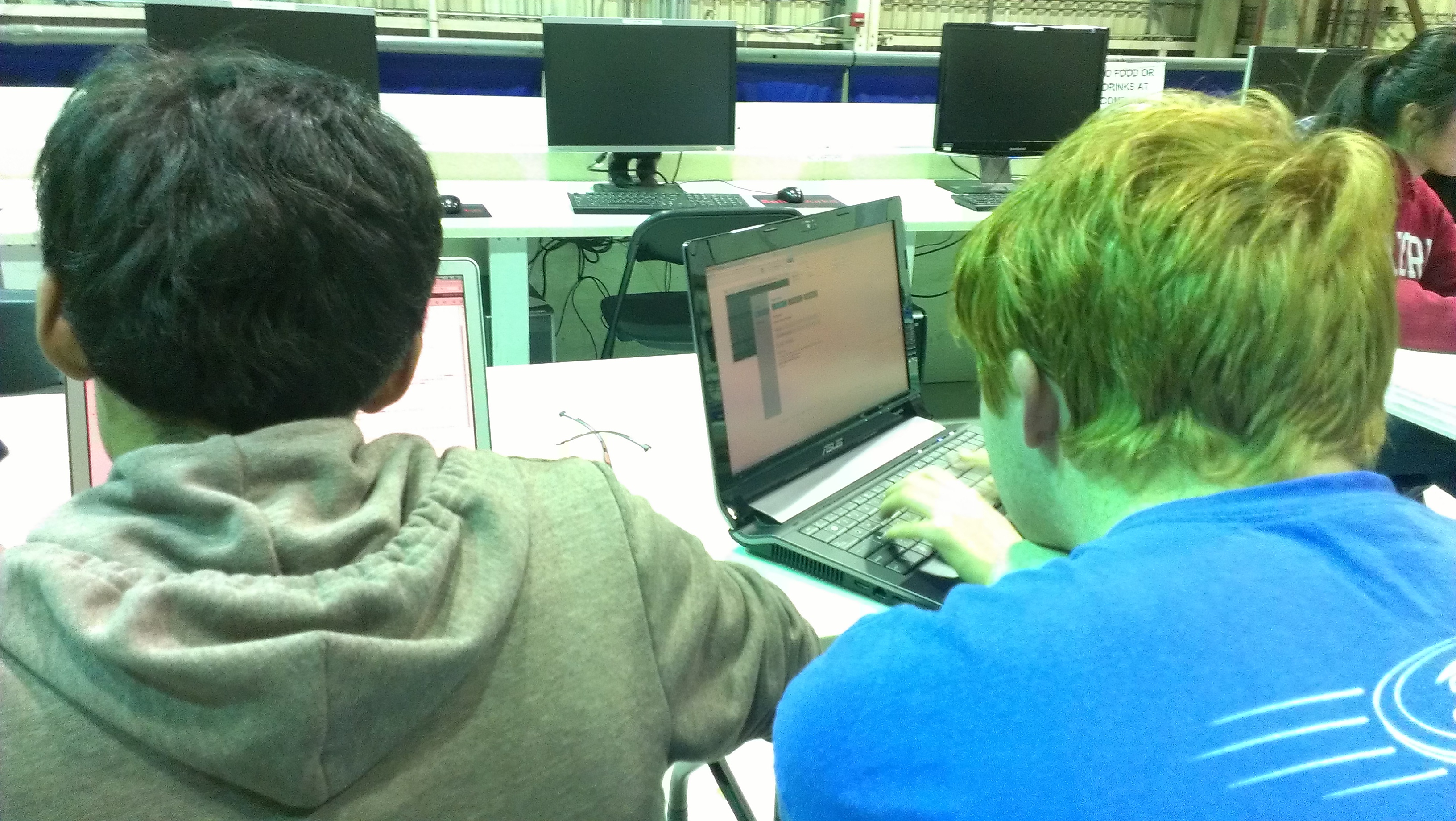
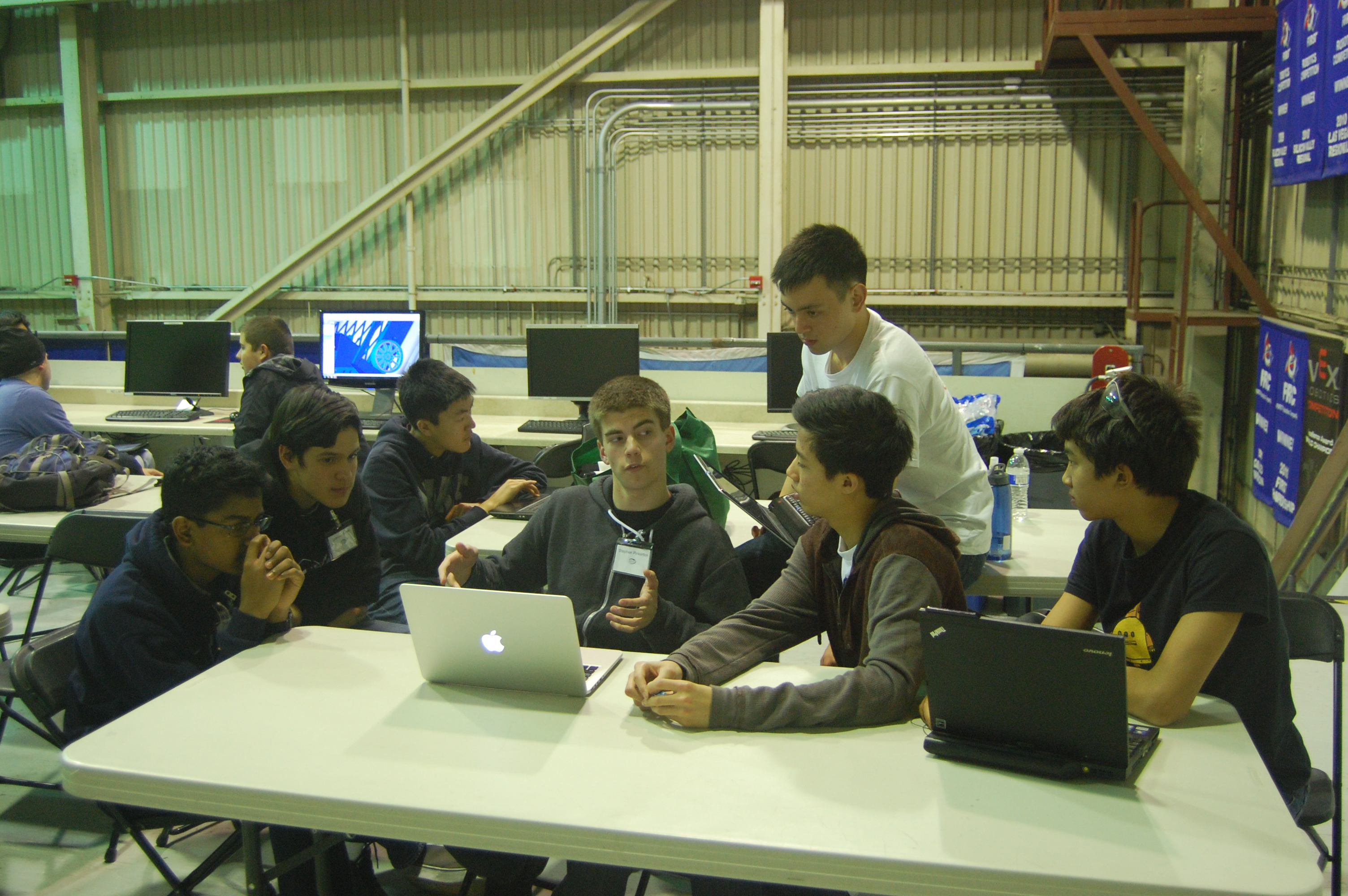
Programming
The programming team worked hard on the coding on day #6. Today they made it so that the robot can now serve HTML pages. Furthermore, they had to refactor some of the code. In conclusion, while they had to restructure the code, this change did not affect how the code behaved.
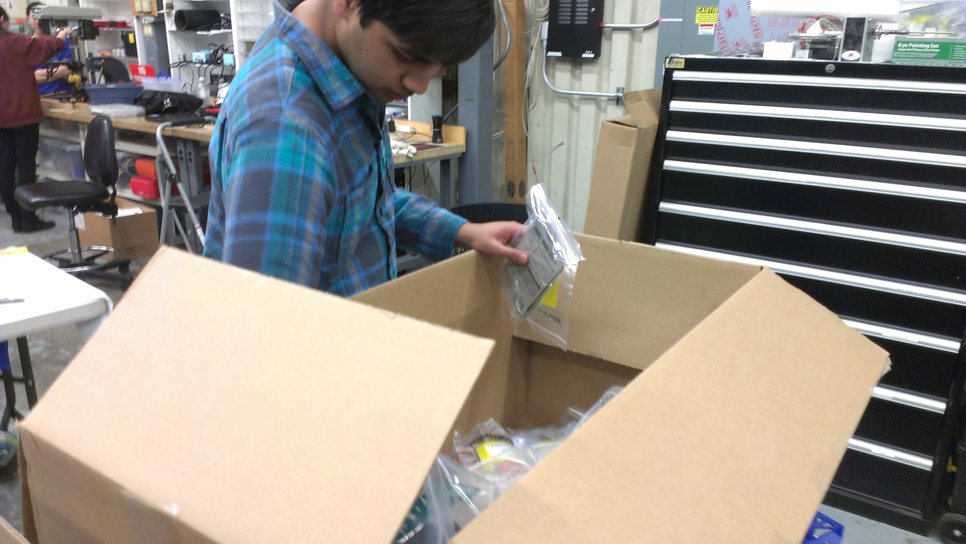
Organization of New Equipment
Recently, we received new equipment for the lab, such as soldering devices and other tools. Several students helped organize these new parts and categorized everything received into an Excel document, creating in effect an organized system of all the new equipment within a neat document.
Action Items
- Continue helping Abhi and Dan with catcher prototype and an add intake system.
- Continue helping Ahmed and Paul with shooter prototype improvements
- Continue testing
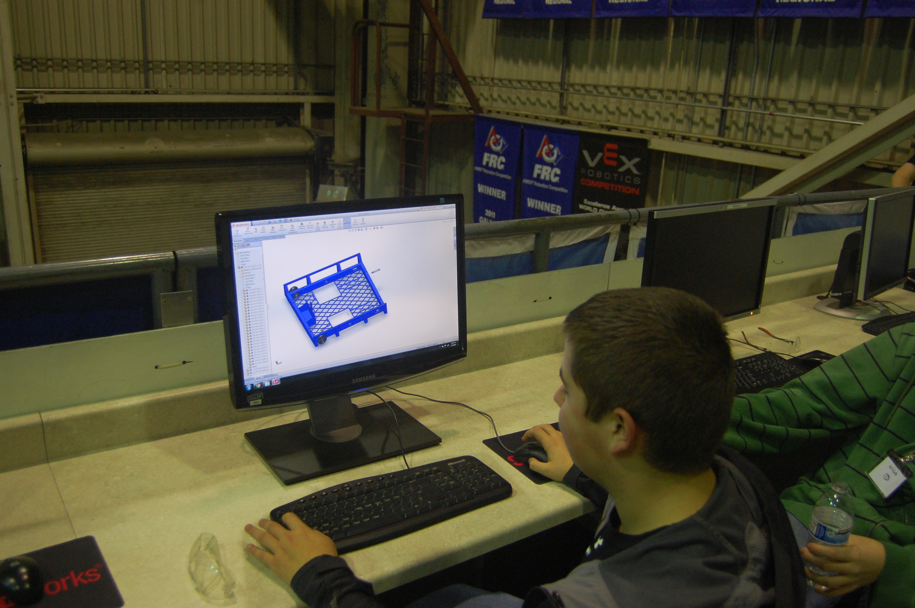
- Continue working on the drive base CAD with Andrew
Day 5: More Prototyping and Gearbox CAD
Flywheel Shooter Prototype
Today, we continued work on a new flywheel shooter prototype. The team determined that smaller shooter wheels would make the shooter more packagable in the robot. We made some great progress and we should be able to complete it tomorrow.
Design
Work continued on the drive gearboxes today. Based on the results of the simulation discussed yesterday, we decided that we would move forward with 2 3 CIM motor gearboxes but would also design 2 CIM motor gearboxes that could be swapped in if necessary. Although this would reduce acceleration, it could lighten the robot by up to 8 lbs.Today, we added the Bimba pancake pistons to the two speed gearbox assembly. We are moving forward with the previously discussed ratios of 4.2:1, 19.6ft/s in high gear and 10.6:1, 7.6ft/s in low gear. The CAD is almost done and is only missing a few components.
Programming
Today the programmers continued work on the graphing system for the robot. They worked on getting a TCP/IP server running on the robot and working out the technicalities of using a browser to monitor the stream of data from the robot.
Action Items
Finish Gearbox CAD, begin finalizing Drive base CAD
Day 4: Prototypes, Coding, Drive base design
Catcher Prototype
Today, we continued work on the catcher prototype, making it higher and wider so that it can better catch balls from all angles. Although the catcher is promising, its large size may be a problem when packaging mechanisms for the robot.
Catapult Prototype
The catapult prototype was finished today. The shooter is very smooth and can be easily reloaded in less than 5 seconds. It is consistent and accurate from up close (~2 ft from high goal) but mediocre from midway to the white zone. This shooter suffers from inconsistency in ball positioning within the catapult which could be improved with a better ball cradle.
Flywheel Shooter Prototype
The flywheel shooter has been the most successful thus far with accuracy, precision, range, and simplicity. Because of its success (especially in scoring all 3 balls in under 5 seconds), we took it apart to replace the large wheels with smaller wheels while narrowing it to maintain ball compression with the smaller wheels. We hope to test this tomorrow.
Programming
Today, the programming team worked to get the 2013 practice robot up and running to test the drivebase. Several problems were encountered along the way. First, they had an SDK error on the robot which took them a long time to fix – eventually a cRio reflash solved the problem. Second, there was a problem with the wiring on the robot so they weren’t receiving any data from the TCP server. They eventually fixed the problem and now they are working on a way to graph the data from the robot in a quick and easily readable way.
Over the next few days they will also work on are prototyping some autonomous for the robot as we determined the autonomous is very important strategically.
Autonomous Strategy
We have determined that the autonomous period is critical to our success in Aerial Assist, allowing the robot to score up to 65 points. Because of this, we want our robot to be able to score 3 balls in under 5 seconds. The flywheel prototype is the most promising for meeting this objective.
Over the next few days, the programming team plans to start working on drivebase control loops for autonomous, using Overkill as a practice base.
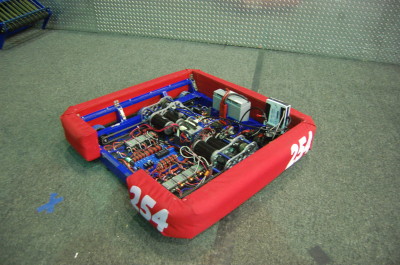
Drivebase Design
Today, work began on the robot drivebase, taking heavy inspiration from last year’s robot. The robot’s 6WD drivebase is the same overall size (28″ W x 27.75″ L) with wheel wells that can accommodate up to 1.5″ tread width. Today, we created a rough chassis in CAD and started work on the 2 speed drive gearbox.
The planned drive speeds are similar to last year (3 CIM motors per gearbox, 12:40 inital reduction, 15:48 low gear reduction, 28:38 high gear reduction, 3.5″ wheel diameter, 19.6 ft/s & 7.7 ft/s theoretical speeds). Due to the tight clearance between the 40T gear and the dog, the outer diameter of the dog will need to be reduced somewhat. Overall, this is a very similar gearbox to last year.
To determine the acceleration performance of our planned ratios, we performed a simulation of the drivebase accelerating. We decided to optimize the robot for 10-15 foot sprints and found that the ratios worked well with these goals. Furthermore, we found that while the 6 CIM drivetrain could reach 10 or 15 feet 10-20% faster than the 4 motor drivetrain, it drew much more power and could lead to premature battery drain.
Action Items
- Test flywheel shooter prototype.
- Test intake prototype with Mani.
- Continue working on drive base and gearbox design with Nagy.
- Compare all 3 shooter prototypes and decide on which we want to use.
- Continue work on drive code and autonomous planning with Stephen and Brandon.
Day 3: Prototyping continued, Autonomous strategies, and more
Autonomous Strategy
Today, we discussed scoring all three balls in autonomous. In autonomous, only the area directly in front of the low goal is guaranteed to be undefended. The strategy would involve starting with one ball in the robot, one in front and one behind. The robot would immediately drop an intake on each side of the robot and drive to the hot goal to score, dragging the balls with it. We also discovered that a banner sensor was able to pick up the reflective tape, meaning that the robot wouldn’t need to a camera to detect the hot zones.
We discussed whether it was more beneficial to shoot from afar or really close to the goal. Several team members proposed that shooting 2-4 feet away would be best since it would more than likely increase the robot’s accuracy. The fly wheel shooter was set up about 3-4 feet away from the goal and was able to successfully score
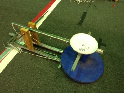
Catapult Prototype

A group today worked on a catapult prototype. A good amount of progress was made and it seems to be coming along well. The only things left to add are the rope, springs and hard stops.
Ball Catcher
Some of the students worked on a basic catcher prototype, making it from PVC pipe. They added a funnel to the top to increase the likelihood of the ball going in. It worked out well with some minor strengthening.
Programming
The programming team worked on a basic autonomous runner that uses threading. In essence, it allows for commands to be run while still allowing evaluation to occur. Also, in the event that a command should fail or timeout, the robot will skip the rest of the commands. One of the ideas that was brought up was separate compilation for the main code and autonomous routine to allow for quick changes to the autonomous without having to recompile the whole codebase.
Day 2: Prototyping, Drive base Design, Initial Coding
Prototyping Shooters
Three different teams worked to design, build, and test three different ways to launch the ball. They built a catapult, a linear launcher, and a flywheel shooter.
Catapult Launcher
A catapult was designed and built today using a system similar to other catapults we’ve seen for this year and 2008. This quick prototype was not strong enough to launch balls far enough and the team needs to improve the design tomorrow perhaps by making it more stable and utilizing another tension device such as surgical tubing.
Linear “Trident” Launcher
Flywheel Shooter
The flywheel shooter was completed today, and students and mentors began testing with it. Of the three shooter prototypes, the flywheel had the best shots and most consistency. Additionally, the team could test the effects of ball pressure on the consistency and accuracy of shots for the first time in the season. By the end of the night the flywheel shooter made about 1/3 to 1/2 of its shots.
Programming
The programmers met today and decided on what they wanted to work on for the next few weeks.
It was decided that we would like to spend time building debugging tools for the robot. The main thing that needs to be built is a way to live graph motor and sensor states, much like the PID tuner we had in 2012.
The programmers also decided to rework how autonomous mode will be executed so that control flow can be used in autonomous rather than just a straight sequence of events.
Tom and Stephen started a new Java project for the 2014 robot and got basic CheesyDrive working on the 2013 practice drivebase. This code will use a new subsystem architecture and will use very little code provided by WPI.
Field Assembly
The team completed the construction and mounting of one full set of high goals. The goals have a ramp designed to return the balls back onto the field so that they do not fall onto drivers. We will use these wooden goals while we wait for the official set to come in from FIRST.
Drive Base Design
Today, the team began modeling parts for the gearboxes and chassis. We plan to design a drive base similar to last year but without a PTO on the gearbox. Tonight, we designed the gearbox output shafts, intermediate shafts and wheel shafts which will be sent out to sponsor Modern Machine Company tomorrow.
Action Items
- Continue gearbox design
- Continue testing and improving flywheel prototype.
- Continue testing puncher prototype, try to increase power.
- Rebuild catapult prototype, must be stronger and more stable.
- Programmers continue improving drive code and autonomous tuning with Tom.
- Improve catcher prototype with Dan.
- Possibly begin machining parts for the drive base.
Day 1: Kickoff and Game Analysis
Kickoff Overview
Today kicks off the 2014 FRC Season for Team 254. The mentors and students are equally ecstatic for this year’s challenge, Aerial Assist.
Google Drive PDF of the Game Manual:
https://drive.google.com/file/d/0B_TTQ23_FVkAWjM0cjBsbUw1TkU/edit?usp=sharing
Game Animation:
Team Kickoff
Today a group of students attended the 6:30 to 9:30 local San Jose kickoff at Morris Dailey Auditorium. A few others watched the NASA Live Stream from home. Subsequently, at 10, the team met for the team’s kickoff event and discussed the plan for the coming six-week build season. The team then broke up into groups and discussed strategies in terms of necessary robot qualities, priority tasks, and possible scores. The parents and mentors simultaneously discussed logistics and the build plan in more detail until the student leaders returned to present their ideas to the entire group.
Game Analysis
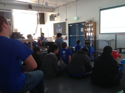
After lunch, about 70 students congregated in the Bellarmine Robotics Lab to examine and better understand the team rules. In particular, they discussed the definitions of assist and possession and clarified the rules for such actions and others on the playing field. For the first two and a half hours, the group went through the relevant sections of the game manual and encouraged group discussion to find possible holes and list them to check with FIRST later. The group noticed some deviations in rules from previous years: the field is two feet narrower at 25 feet, and the match is 30 seconds longer. The autonomous period is five seconds shorter at 10 seconds, and the tele-operated period is 35 seconds longer at 2:20. Andrew Torrance noted the possible issues with battery life with the 25% longer match time. In addition to discussing rules, the team also formulated questions concerning the regulations to ask FIRST:
- Can teams do assists in autonomous?
- Can teams hold balls in autonomous to do an assist later?
- Can a team throw over the truss again to try and get a catch, say, if an alliance earns a successful truss score, but does not successfully catch. Can the alliance try for a second chance? In other words, while the group recognizes that only one truss score counts per cycle, do the truss score and the associated catch score have to be earned on the first attempt?
- Do teams get points (ex. throwing and catching in the end game) immediately, or do the teams only get them once the cycle completes? This is related to the question of assisting in autonomous. Possible answer: Maybe not because autonomous shots are not cycles.
- Teams need clarification on which goalie zone to which the initial position regulations refer. In which goalie zone do teams start if they do not want to start in the white zone? Can human players help in the middle of assists?
- Can human players catch truss scores to make them legal?
- Teams need a better definition of possession for robots in general. For example, for a trough-like robot, is holding the ball as it rolls considered possession? What time period differentiates harmless “deflection” from “possession” of the opponent game object (which earns a severe technical foul penalty)
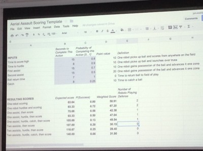
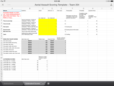
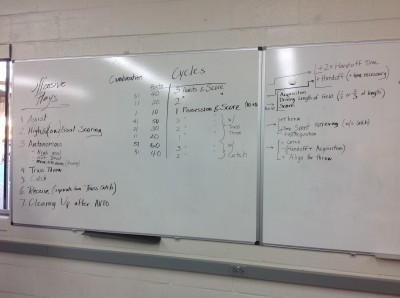
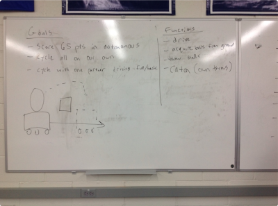
After a short break, the team’s new mentor Jared set up a Google Spreadsheet that evaluated the effectiveness of certain “assist” strategies, with combinations of 1-3 assists, a truss “hurdle,” and the truss “catch.” He took student input for the point values corresponding to each action, the expected time taken for each action, and the probability of the action being carried out successfuly. He then calculated out a rough model of the weighted point values expected from strategies in the tele-operated mode of the match. The group was then able to analyze the efficiency of certain strategies. In the process of discussing strategies, the team also created two other strategy charts and lists (pictured).
Further Analysis and Prototyping
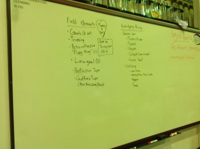
After dinner, approximately 20 students worked with the mentors to list some possible designs and to plan out the next week’s prototyping schedule. The group prioritized the prototyping of possible modules, specifically shooter designs and catching mechanisms, with design input from students and advice from our experienced mentors. They also discussed what field elements were most necessary for prototyping for the next few weeks and listed them as well. Finally, they discussed the mathematics and physics of shooting a 25-inch, compressible, bulky, and irregular projectile into a 3-foot goal. For example, mentors noted that we might as well design a robot to shoot from farther away from the goal, since the shallower angle of entry would give greater allowance for error. Mentor Paul Ventimiglia also determined that giving the large exercise ball some backspin helped in precision, though it also required more energy to apply both linear force and rotational torque.
Tonight, we mainly focused on the building a preliminary goal with which to prototype before the field arrives and on prototyping and testing the effectiveness of a flywheel shooter and a slingshot shooter. Paul worked primarily with Godwin Vincent, James Holden, Jeremy Tanlimco, Vidur Maheshwari, Miggy Francisco, and Joncarlo Avila to design, sketch, and begin building a prototype for testing the effectiveness of a flywheel on such a large game object. They determined the best wheels with which to work based on their ability to grip the surface of the unusual game object. The prototype design was finalized and they plan to use four large wheels on the same axle hooked up to curved plywood “rims” to optimize the compression on the ball and somewhat minimize the size of the already bulky prototype. EJ Sabathia and Noah Marcel worked on the slingshot design, taping a 2013 Ultimate Ascent Frisbee to surgical tubing and hooking up the system to an alliance wall. The ball consistently bounced about 1/3 of the way down the court, given about 4 or 5 feet of backward stretch.
Lab closing time: 11:00
Action Items
Translation: Future Work Opportunities for Members
- Help Paul with the Flywheel Shooter design
- Help EJ with Slingshot Shooter design
- Help Nick Mercadante machine metal for prototypes
- Ask mentors to begin and lead prototyping projects for other designs
