
Blog Archive
Build Blog Day 11 (1/24/18)
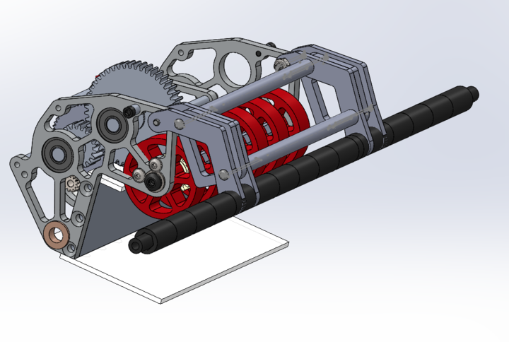
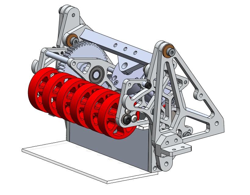
Elevator
Task: Design Elevator Cartoon CAD
-
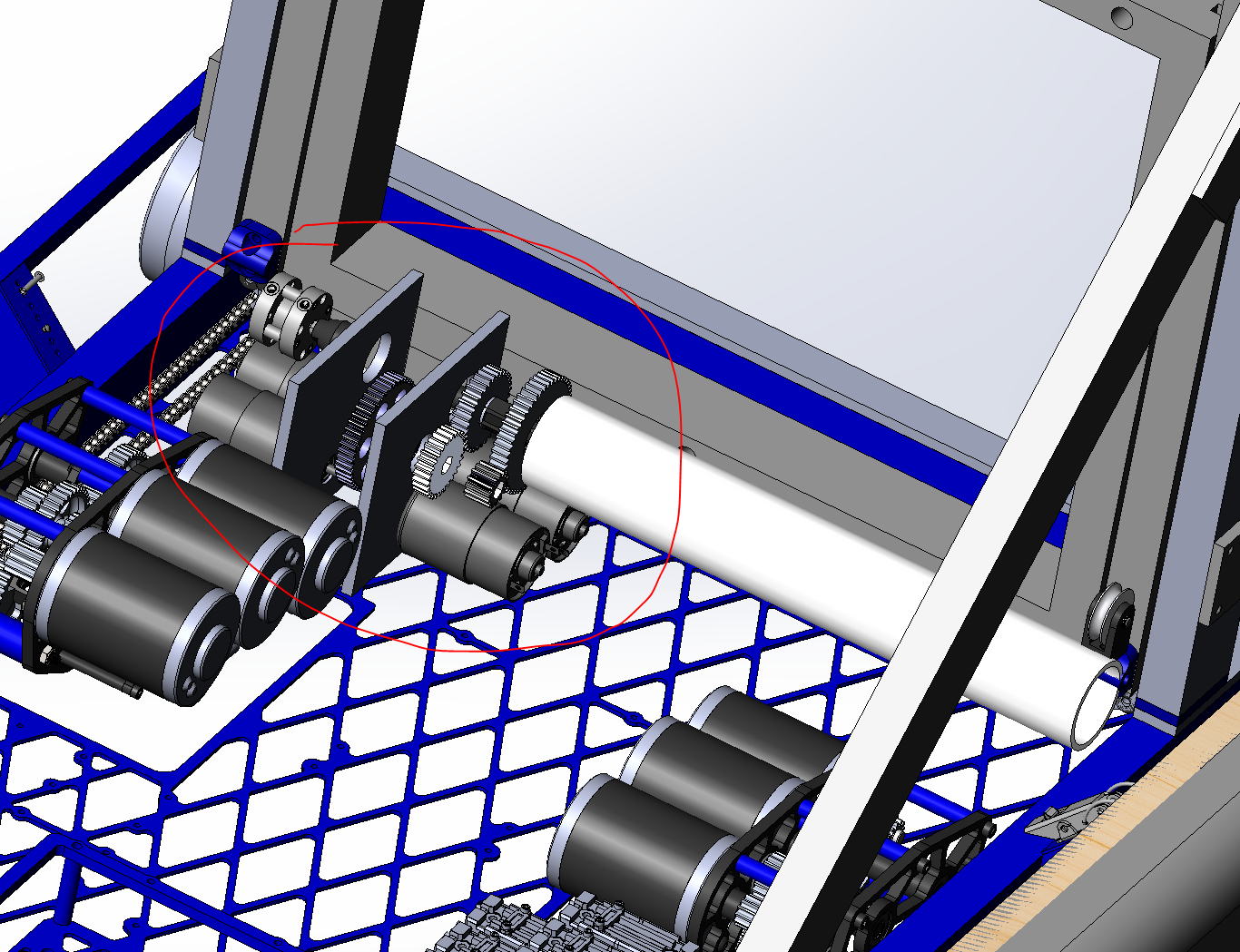
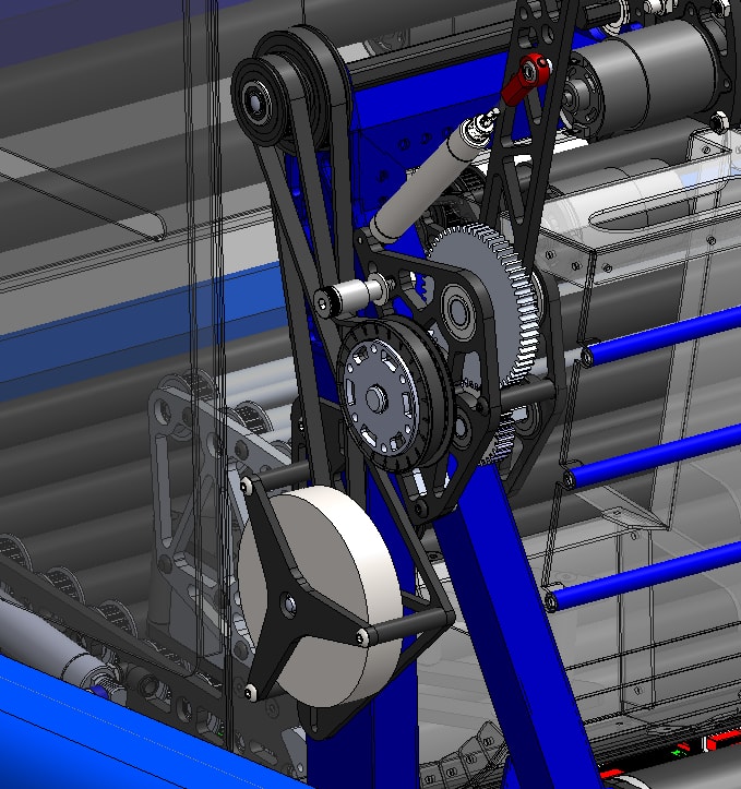
The previous issue with Option B was the issue of the spool not being low enough if we directly mounted it on the shifter shaft. To address this issue, we decided to add a 1:1 reduction to lower the spool down. We also talked about the horseshoe. The horseshoe allows us to drop the intermediate stage as low as possible such that we can score our cube safely into the exchange.
Option A:
Option B:
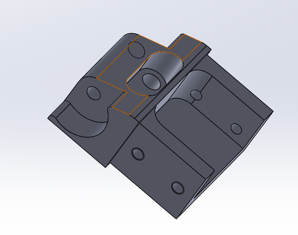
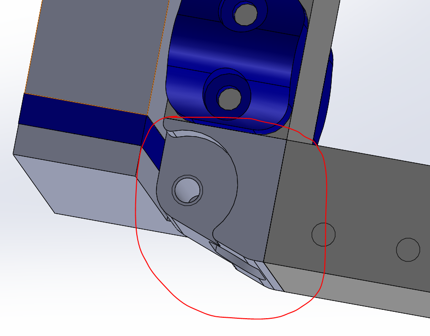
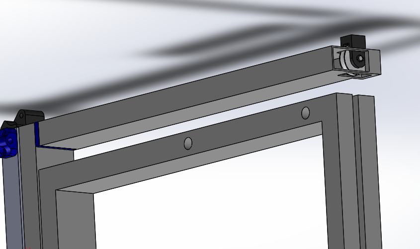
We also designed new bearing blocks to allow us to save an inch of space between the vertical and horizontal tube of the intermediate stage.
Forklift
Task: Finish Forklift CAD
-
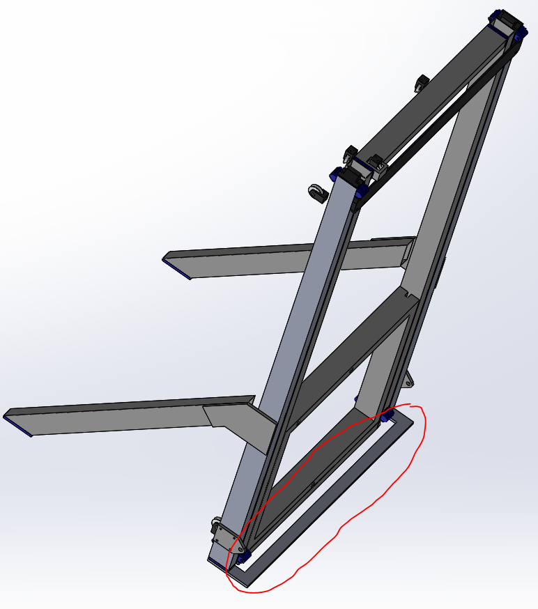
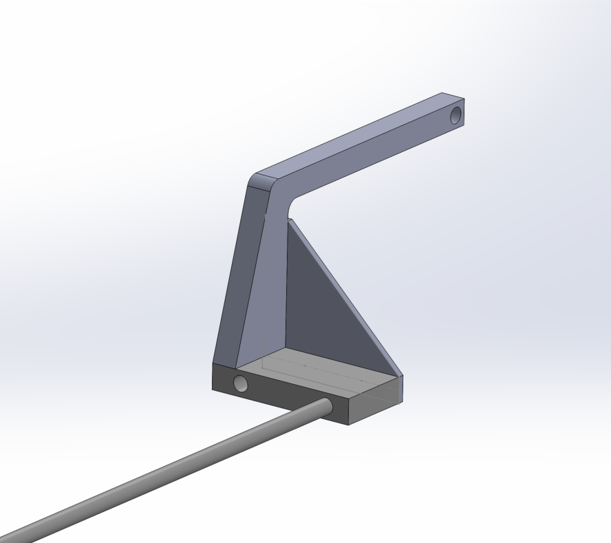
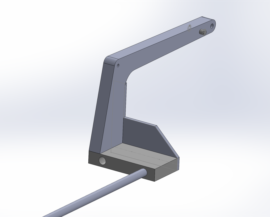
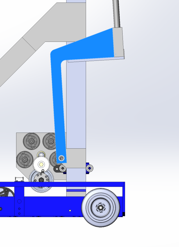
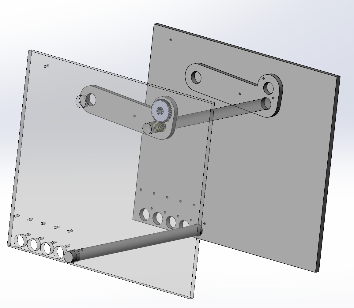
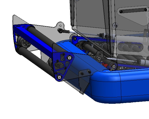
At Wednesday's build, we worked on further detailing the forklift arm. More specifically, we added a point to the back of the arm where surgical tubing could hook onto it and in-effect spring load it downward when we are ready to climb. We also beefed up the main arm and added a pivot point just above the downward 90 degree angle of the arm, which will later serve as an attachment point for a tensile member that will help support the whole arm when we are lifting another robot. Finally, we added a small notch in the triangle brace to allow room for the elevator superstructure. Moving forward, the plan is figure out how we will release the arm from a stowed position, and run a simulation to make sure the arm can support another whole robot.
Before:
After:
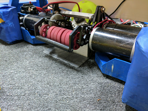
Intake
Task: Decide on a final intake prototype
-
Yesterday, we decided to switch up the intake design and started designing an intake that uses several 2" compliant Andymark wheels as opposed to the 4" we had been using so far. We began designing it in cad but have not laser cut it yet.
Programming
Task: RPLIDAR Driver
-
We got the RPLIDAR to output data to Network Tables, and can now access it from the node.js server. However, there are still some bugs to be fixed – for example, the data stops sending after a certain amount, and we will need to look into the problem more to find out why. Also, we will need to parse and send the data from the node.js server to the visualizer to complete the transfer of data from RPLIDAR to visualizer. Meanwhile, we also researched more line detection methods and are working on finding the best one for our purposes.
Build Blog Day 10 (1/22/18)
Drivebase
Task: Finalize Drivebase CAD and Prepare For Manufacturing
-
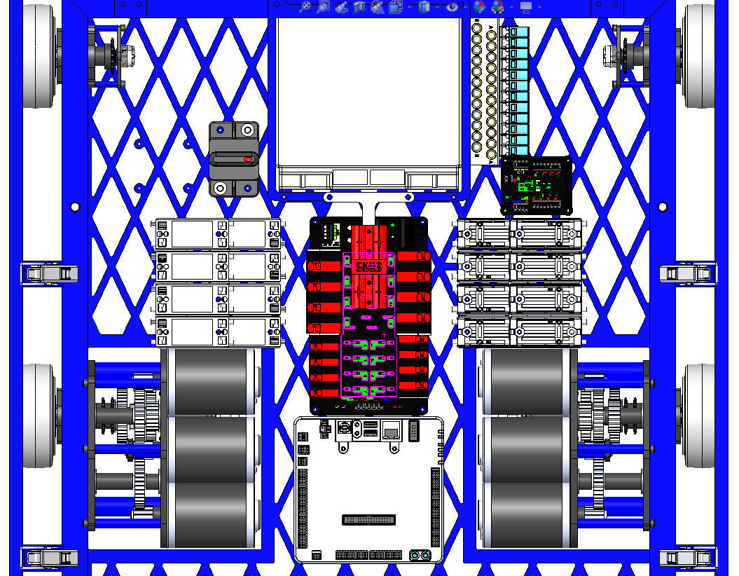
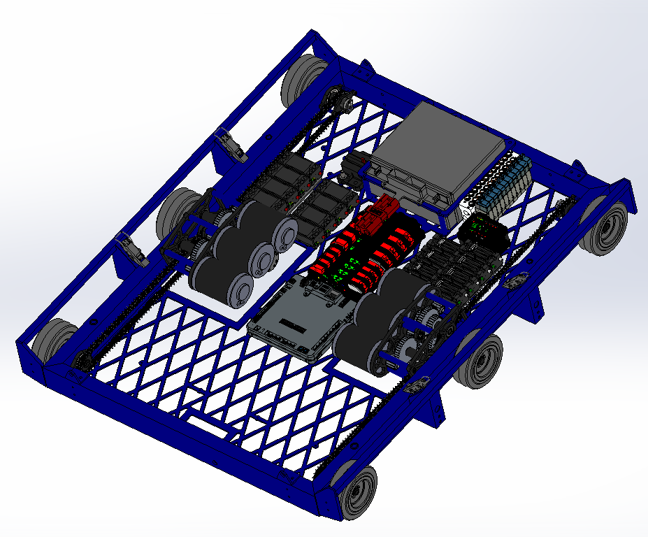
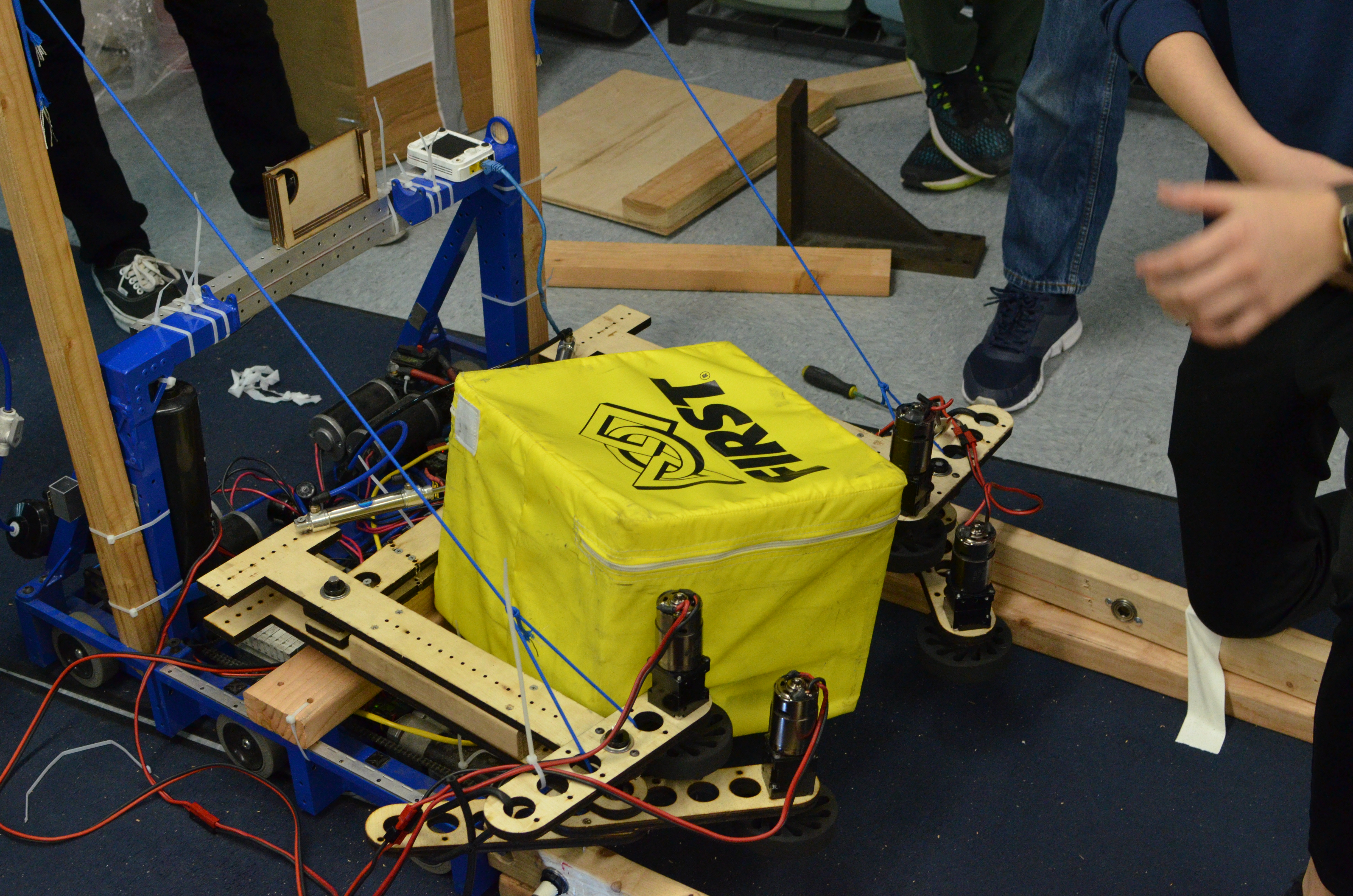
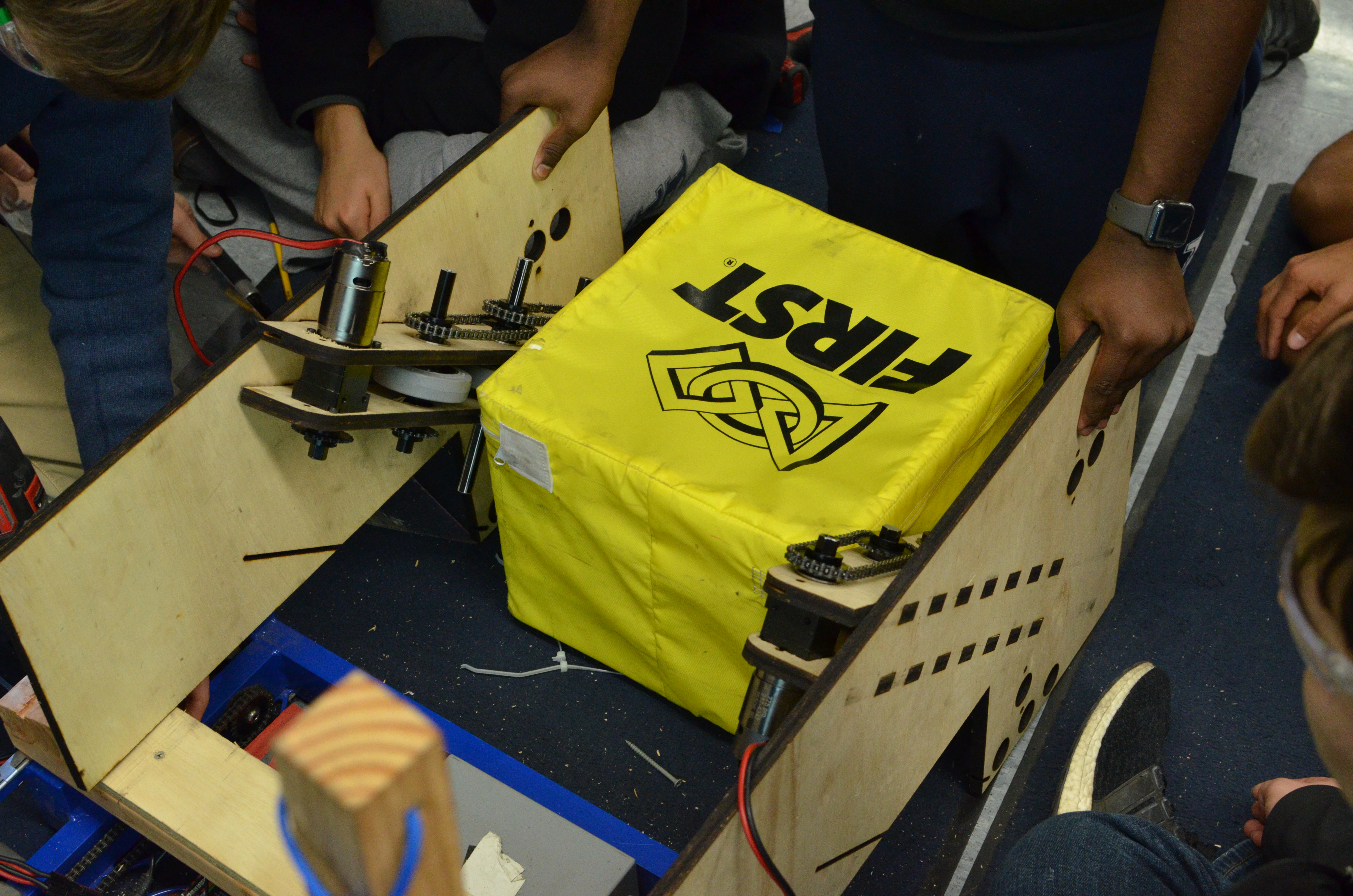
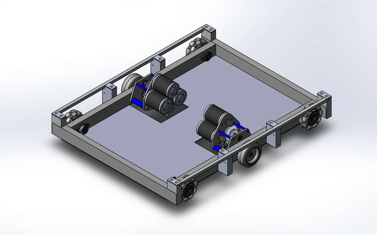
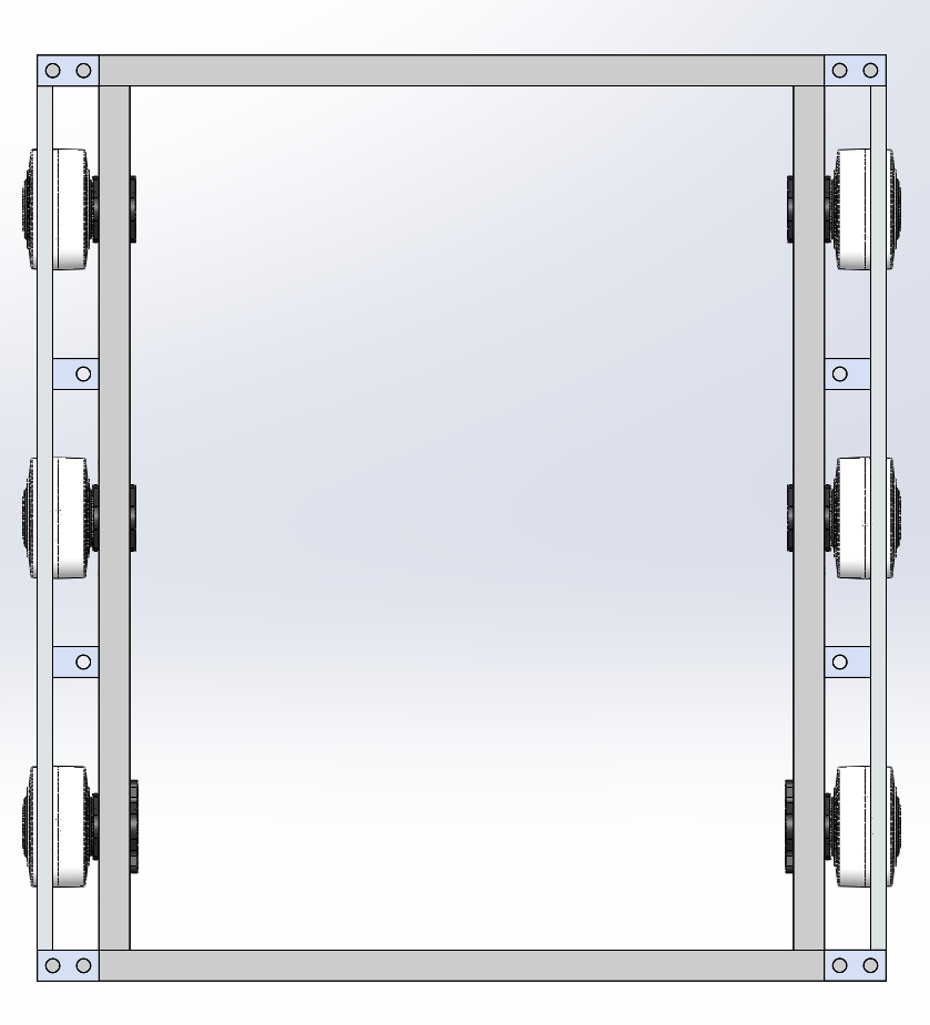
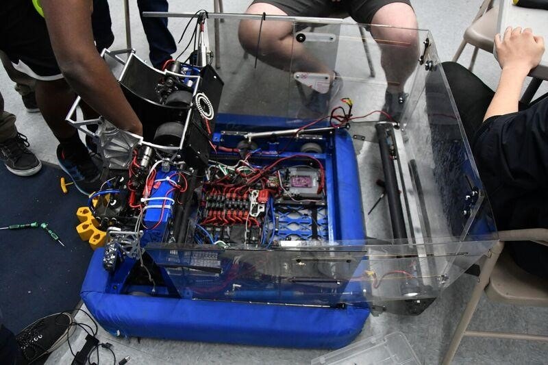
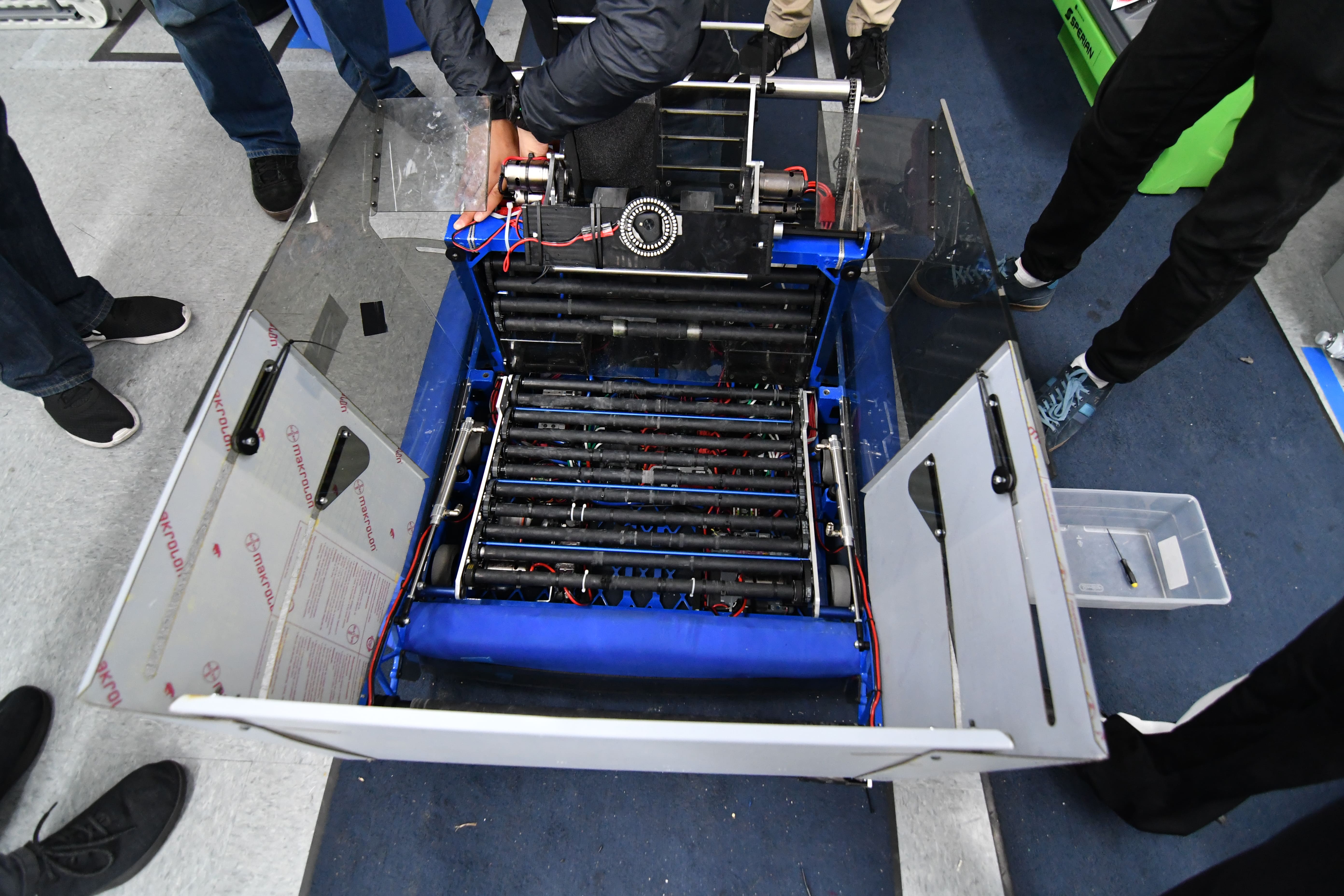
Over the weekend, we finished CADing and reviewing the drivebase. We sent the baseplate out to be laser cut. At our next build, we need to manufacture and assemble the drivebases so they can be welded on Thursday. On Thursday, we will need to deburr the drivebases so that on Friday they can be anodized. For a image of the electronics layout, you can look below.
Forklift
Task: Finish Designing Forklift CAD
-
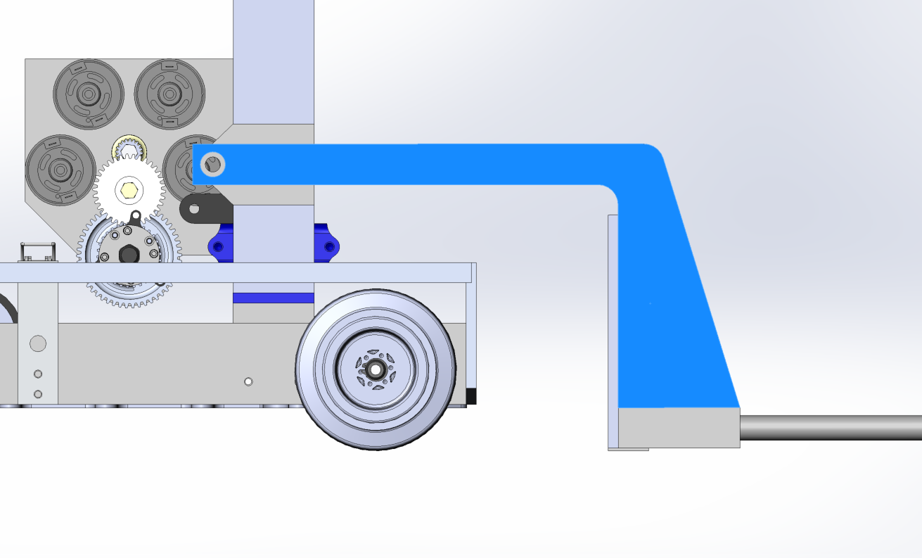
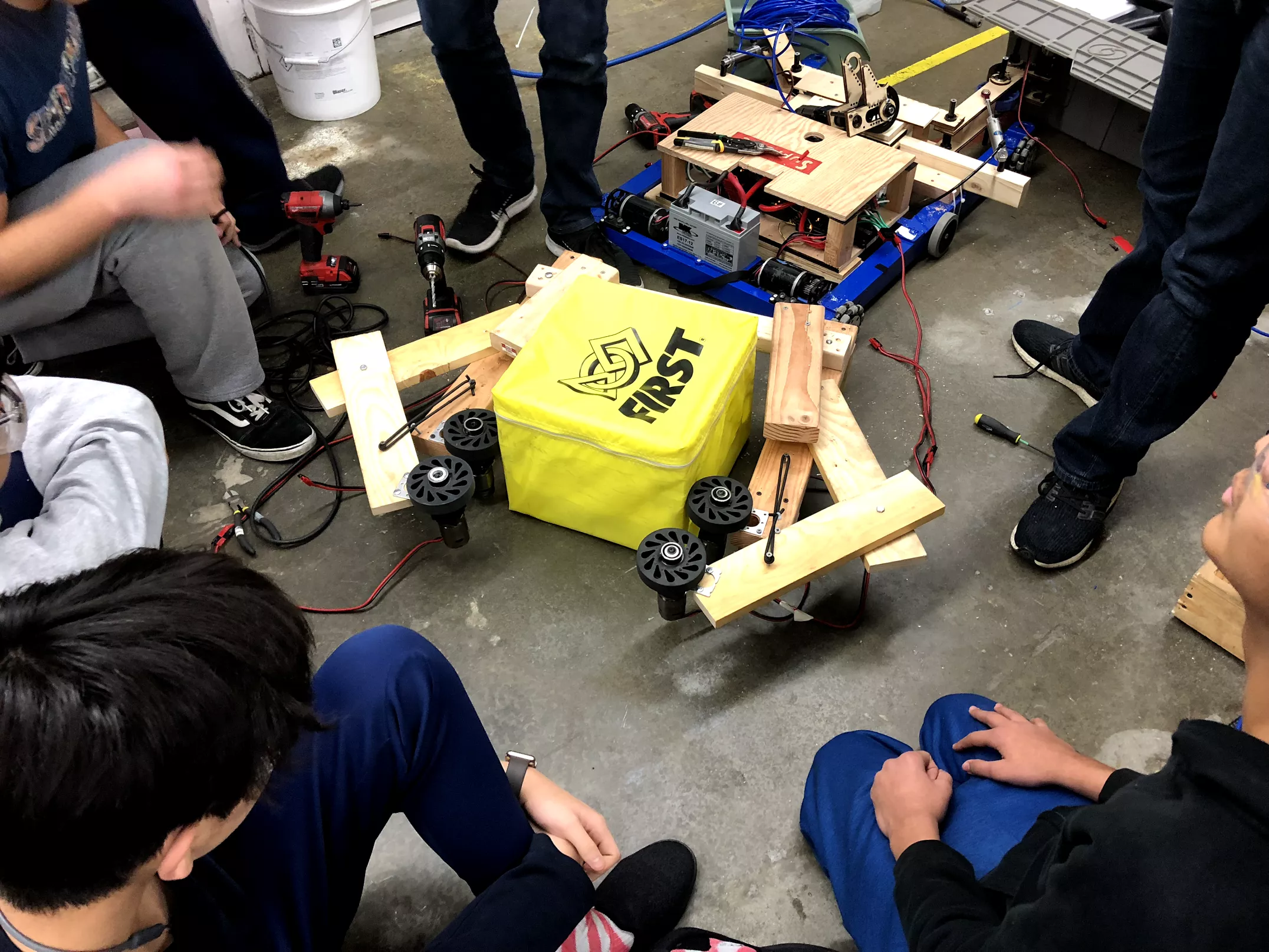
On Monday, we started the build by designing the forklift arm that we would be using to carry other robots at the end of the match. This design certainly needs some refinement, but the image below can give you a rough idea of what it looks like.

-
Some of the other challenges tackled during build were stowing and packaging in a space that is already really crowded with other subsystems. The roller coaster wheels that are still being designed need to fit into the same general space, so we spent a decent amount of time working with him to make sure that our designs didn't collide with one another. On Wednesday's build, we will look into this a bit more and get it reviewed before we start detailing each sub assembly.
Elevator
Task: Design Elevator Cartoon CAD
-
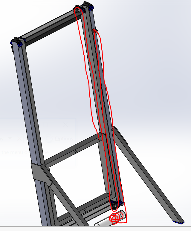
Today, we investigated different gearbox options to power the elevator. Both options contain 2 speed gearboxes (high gear for fast cube cycling and low gear for hanging). One option is to mount the gearbox is to have it attach off the side of the upright such that the motors do not interfere with the intake carriage. Another option is to mount it between the elevator crossbar and the baseplate so that we can bring the spool as low as possible. For the cable runs between stages, we are working on deciding whether we want a single pullup cable that is connected to the center of the carriage and is then redirected to the side or having two pull up cables, one on each side of the carriage, and does not require any redirect pulleys.
Option 1 Pulley Path (Redirects and mount off the side of tube)
Pulley Path Option B (No redirects, just pulls on each side of carriage)
Rollercoaster Wheels
Task: Complete designing rollercoaster wheels and find methods for mounting/deployment
-
Since the drivebase CAD has been frozen, we decided to mount the roller coaster wheels to the gusset at the junction of the angled A-Frame support and Elevator Uprights. We plan to finalize this idea at the beginning of our next build.
Programming
Task: Update All Talons and Roborios for Driver Stations
-
We worked on updating our roborios and talons to the latest 2018 firmware. We also updated all of our driver station laptops with the FRC Update Suite. Now that all our electronics are running on 2018 software, it should be a lot easier to program prototypes and test new code as we no longer have to keep switching between 2017 and 2018 code.
Task: RPLidar Visualizer
-
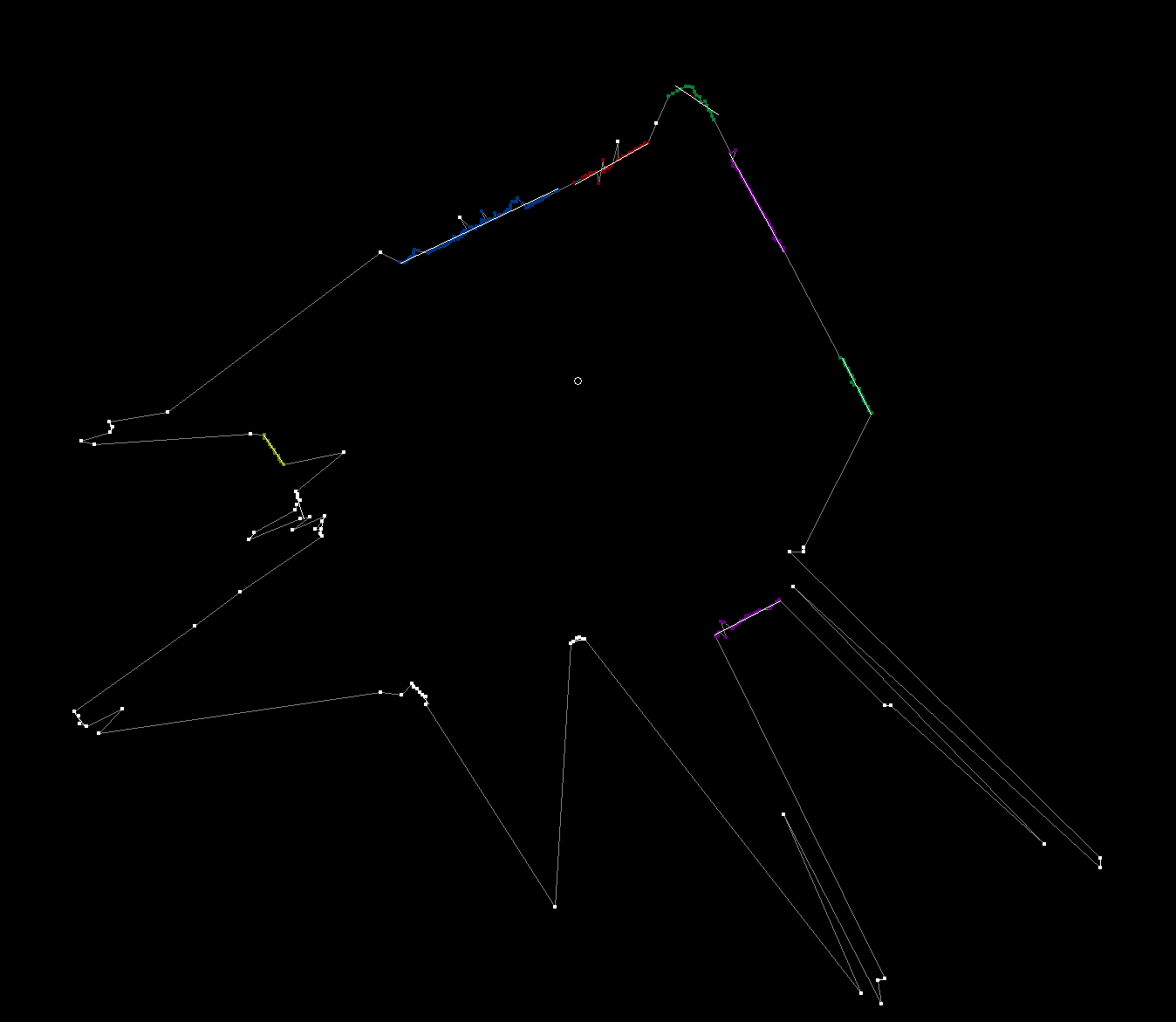
We worked on a field mapping program using the lidar sensor and Google Cartographer. The goal of this program is to push the lidar around the field on a cart and use the scans we get as we move around in order to build a map of the field. We want to use this data to scan a field before every tournament and adjust our autonomous paths accordingly so they are best optimized for small differences. This would be easier and more accurate then the method we used last year, which was to measure the field manually using a tape measure.
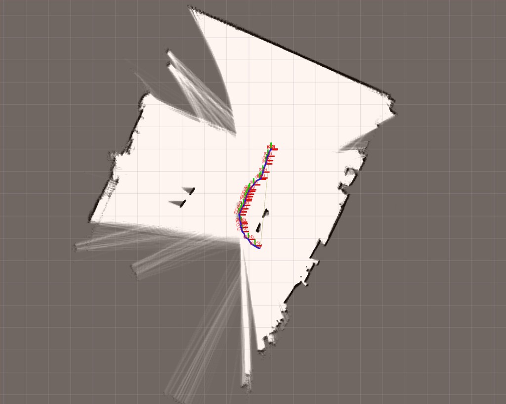
We also worked on an algorithm to determine our starting position in autonomous using the lidar and our field mapping data. We detected clusters of points in the lidar data based on their distance from each other then drew best fit lines through the clusters.
Build Blog Days 8-9 (1/19/2018 – 1/20/2018)
Elevator
Task: Design Elevator Cartoon CAD
-
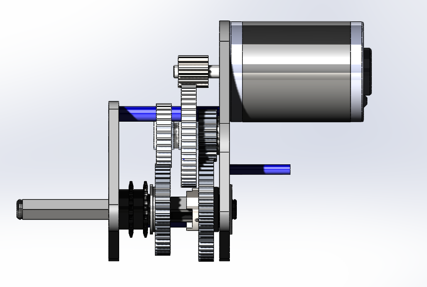
We worked on finalizing the placement of the elevator. The front face of the elevator will be 9" from the outside of the back bumper. We wanted to move the elevator back because we wanted to ensure as confident a handoff between our intake which will end before the elevator and the exchange, but we also needed to leave space for the roller coaster wheels and the forklift. We decided to place a 2×2 crossbar across with 90 degree angle plugs welded in the ends to dodge the chain and mount to the elevator plugs such that the elevator and the crossbar as a whole can come off as one unit. We finalized the gear reductions for the two speeds of the elevator and packaged the gearbox between the crossbar and the drive gearboxes. The gearbox will mount to the 90 degree plugs.
Top Level Assembly: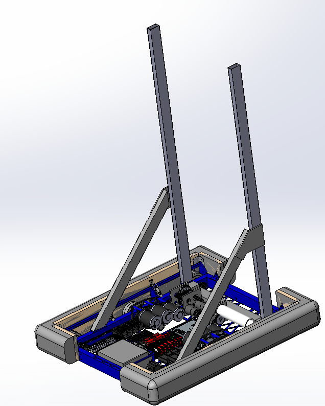
Preliminary Elevator Gearbox:
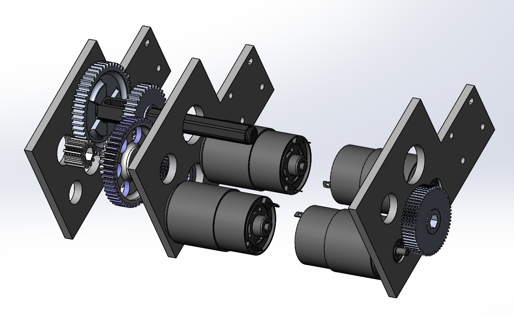
High Gear For The Elevator:
Low Gear For The Elevator:
Drivebase
Task: Finalize Drivebase CAD
-
At the last build, we worked on adding mounts for other parts of the robot to the drivebase and also placing electronics. There were a few requirements we kept in mind when placing the electronics including a horizontal battery (instead of vertical placement) to allow for a tunnel, a possible kicker roller in the front, and the gearboxes in the middle of the robot. Keeping these limitations in mind, we placed the battery in the front of the robot (to balance the center of gravity) and the PDP in the middle of the robot with stacked staggered Talons to each side. See the image for placement of everything else.

Forklift
Task: Complete Forklift CAD
-
Yesterday, we worked on the Forklift design for the 2018 FRC Robot. On Friday night, we started by doing some physics calculations to determine how much the forklift would bend once a robot was on it, and determined that a 100lb force at the end of a single 36in rod we plan on using would yield a 6in deflection. This number seemed like a lot, however when we moved the 100lb force to the center of a rod (18in), the deflection was only about 3/4in, which is very reasonable. The next step was to do some sketching in CAD to figure out where the mounting place for the forklift pivot point would be. After trying to make the forklift arms fit in between the bumper cutout (which ultimately didn't leave enough space for a cube to pass through), and trying to make the arms to go over the bumper (which collided with the elevator superstructure when stowed), we finally settled on having the pivot point for the forklift mount on the elevator superstructure itself. With this design, the forklift could stow vertically, and then come down neatly at the end of the match and react against the robot's frame rail when lifting a robot. Now that we have decided to go forward with this design, the forklift design team will need to work closely with the roller-coaster wheel team to make sure that the two subsystems don't collide with one another, as they are both located in very similar parts of the robot.
Rollercoaster Wheels
Task: Complete designing rollercoaster wheels and find methods for mounting/deployment
-
The intention of the rollercoaster wheels is to allow the robot to climb up straight in the sneaky hang, while preventing our partner from falling off the forklift in the partner hang. Our original plan was to have a single plate mounted to the elevator uprights, as well as a actuation deploying the wheels for both the partner hang and the sneaky hang. However, we were unable to package the plate in such a way to stow inside the frame perimeter. Thus, we decided on two separate plates and actuations for each of the rollercoaster wheels. In addition, since mounting the rollercoaster wheels on the elevator uprights would interfere with the forklift deployment, we are pursuing the deployment of the rollercoaster wheels from the bumper frame rail.
Programming
Task: RPLidar Driver with JNI
-
We made some real progress on the RPLidar Driver using JNI. We finished most of the C++ code for the JNI, which again allows us to call functions written in other languages, in Java. To do this, we adapted some of the code from example RPLidar programs for JNI. Once we were done with the C++ code, we built the code into a Shared Object. Our next steps are to finish the Java code, which will load the Shared Object, parse the data returned, and send the data over NetworkTables to the RPLidar Visualizer. Finally, once all of the code is written, we will do some testing and debugging.
Task: RPLidar Visualizer
-
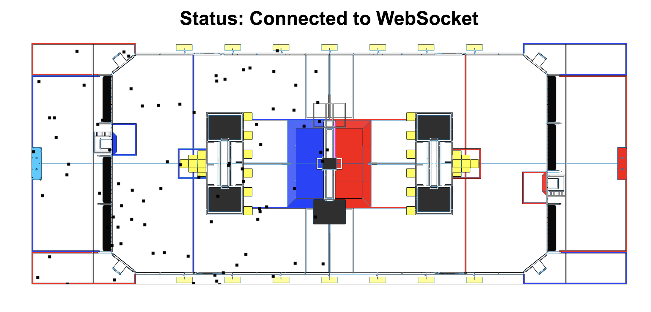
We fixed an error where the RPLidar Visualizer Node.js server was unable to connect to the robot using NetworkTables, which is an implementation of a distributed "dictionary," meaning that named values are created either on the robot, driver station, or potentially an attached coprocessor, and the values are automatically distributed to all the other participants. Also, we updated some formatting on the visualizer to make the timestamp easier to read.
Task: Transforming RPLidar Vectors to XY Coordinates
-
Since the RPLidar scanner only returns an angle (in degrees) and a distance (in mm), we need to be able to transform that to XY coordinates for plotting on the RPLidar Visualizer. To do this, we had to account for the robot's own position and angle, and use some basic trigonometry to transform the vectors into coordinates.
Build Blog Day 7 (1/17/2018)
Drivebase
Task: Cartoon CAD
-
Prior to today, we had the idea of having an intake feed into a tunnel. The tunnel would serve as a conveyor system to transport the cube back and forth across the robot. However, the issues with the tunnel are that a) it will be very bulky and would serve as a huge cantilevered load on the elevator and b) the vertical translation of a cube from the ground to the tunnel (~4.75") would be hard. To solve these issues, we had a new idea where we could have an intake that would pivot 180 degrees to pick up a cube in the front of the robot and then fold back to spit it out on the back side. Since the intake is now taking in and spitting out the cube, there is no need for a vertical translation of the cube and no need for a series of rollers to convey the cube back and forth across the tunnel we need to continue investigating the geometry of this new intake design and make a decision if we want to pursue this design or not by this weekend.
Bumpers
Task: Design a way of attaching the bumper to the drive frame rails
-
We have been working on using latch pieces to latch the bumpers onto the bumper rails. During our next build, we will decide if this is the best way to go and finalize the bumper mounts on the drive frame rails.
Intake
Task: Complete designing the new intake prototype
-
With our new intake prototype design, the intake is mounted on an arm and grips the cube. The arm that the intake is attached to has the ability to rotate back 180 degrees. We plan to have the arm and the intake system itself mounted onto the elevator. When the elevator moves up, the intake arm rotate back and ejects the cube onto the scale or switch. A few issues we are facing and trying to solve, are that we don’t want the intake to be too heavy and we want the intake to have a better grip on the cube.
Build Blog Day 6 (1/15/18)
Gearbox
Task: Design drivebase gearbox
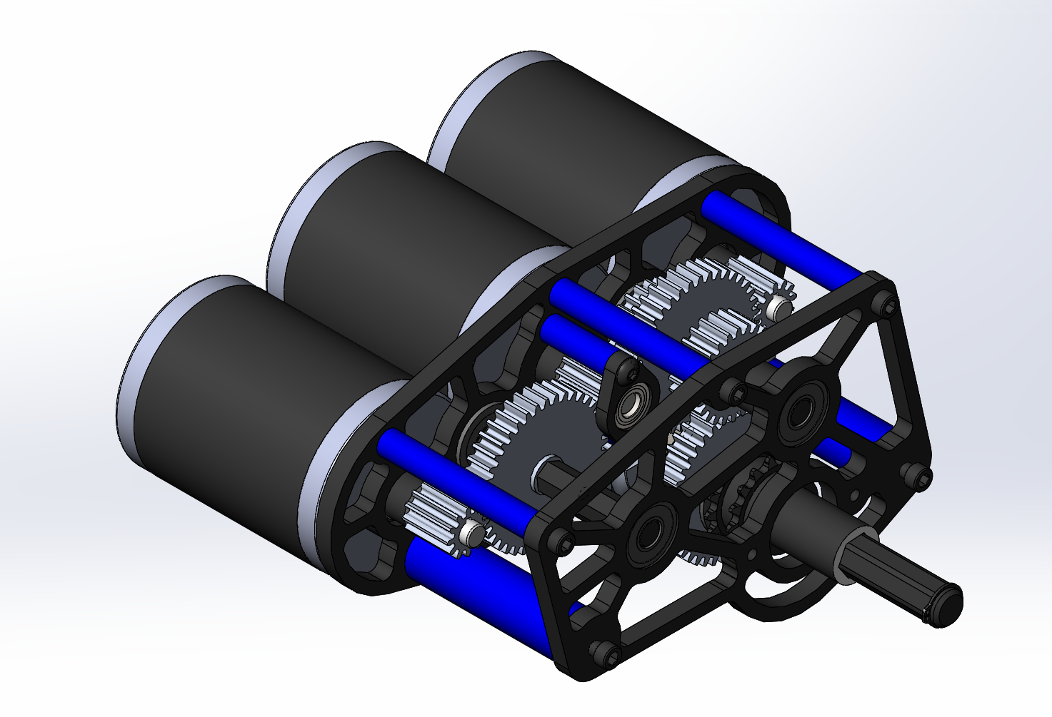
- We found out today that the gearbox will have to be redesigned. Our original plan consisted of a triangle of mini-CIMs but this design was too tall and would not allow the tunnel to lay flat and exhaust cubes to the exchange. Our new design still uses 3 mini-CIMs but they are arranged flat so that they can be lower than the bumper rails.
Tunnel
Task: Design tunnel with timing belts to friction drive the cube across on all four sides
- For the tunnel, we worked on prototyping a mechanism that used timing belts to move the cube.. We made a four bar that allowed us to test the cube in both orientations (11 and 13 in width). Initially, we had trouble with the prototype as there was too much friction between the wood the cube rested on and not enough tension in the belt. We redesigned the prototype and made changes including making the four bar structure more secure, tensioning the timing belt, and installing plastic rails for the cube to slide on. These changes greatly increased the effectiveness of the prototype, and pushed the cube quickly through the tunnel. We now are designing a variation of this but using rollers instead of timing belts, to see which one works better.
Programming
Task: RPLIDAR Driver
- After ensuring that the RPLIDAR works, we discussed several options, and have started to implement two of them. For our first method, we were able to use existing examples of code, from the RPLIDAR’s Software Development Kit (SDK), and write our own program that gets data and a timestamp for that data from the RPLIDAR, and send that data to the robot. Because the SDK is for C++, we would probably have to run this program on a co-processor on the roboRIO that communicates with the rest of the robot code over User Datagram Protocol (UDP). Our other option, which is more preferable, is to use the Java Native Interface (JNI). JNI allows the Java Virtual Machine, which runs Java code, to call functions written in other languages, which will allow us to use the SDK, even though it is written in C++. We will continue work on both of these methods, and choose whichever will work better for the robot.
Task: RPLIDAR Visualizer
- We scaled down points to the size of the field, but this messed with the zooming and panning functions so we’ll have to fix this. Here is a sample image of the current functionality of this interface:
Build Blog Day 5 (1/13/18)
Drivebase
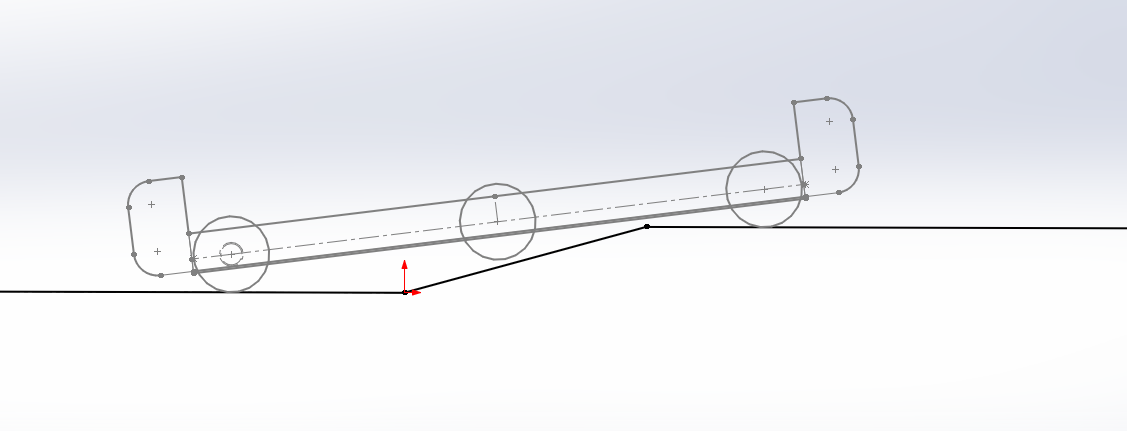
Task: Model drivebase moving up platform ramp with 1/8" center drop and minimal space from outside bumper supports
-
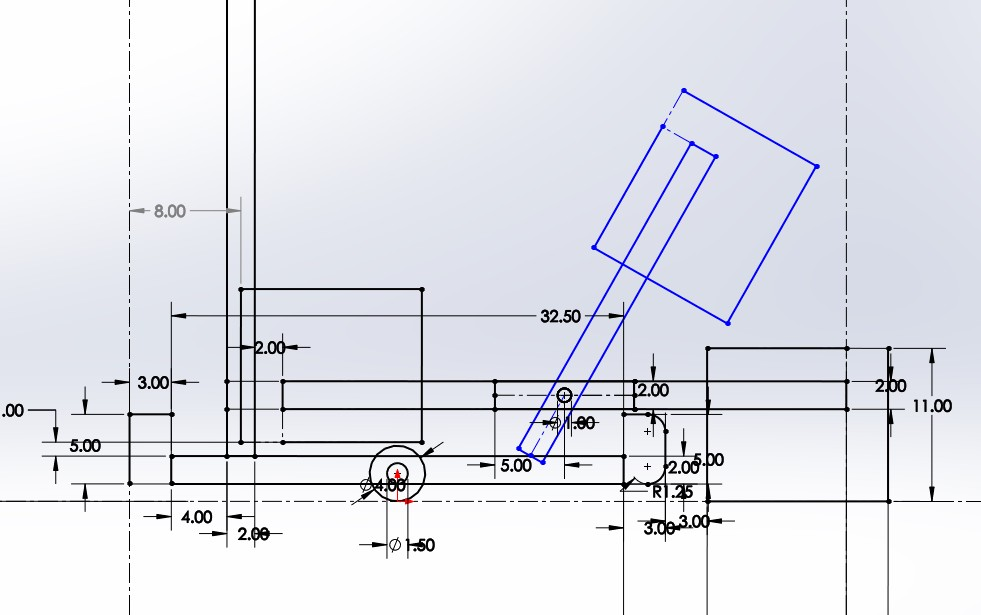
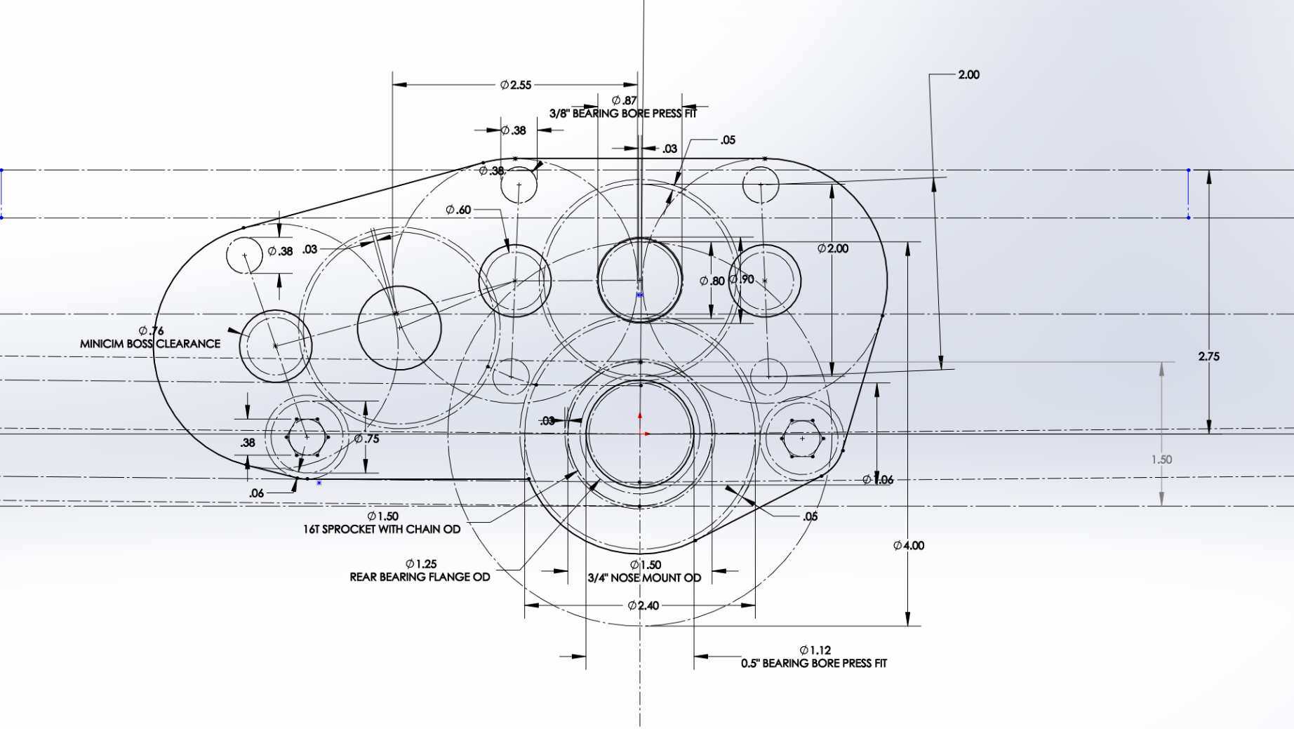
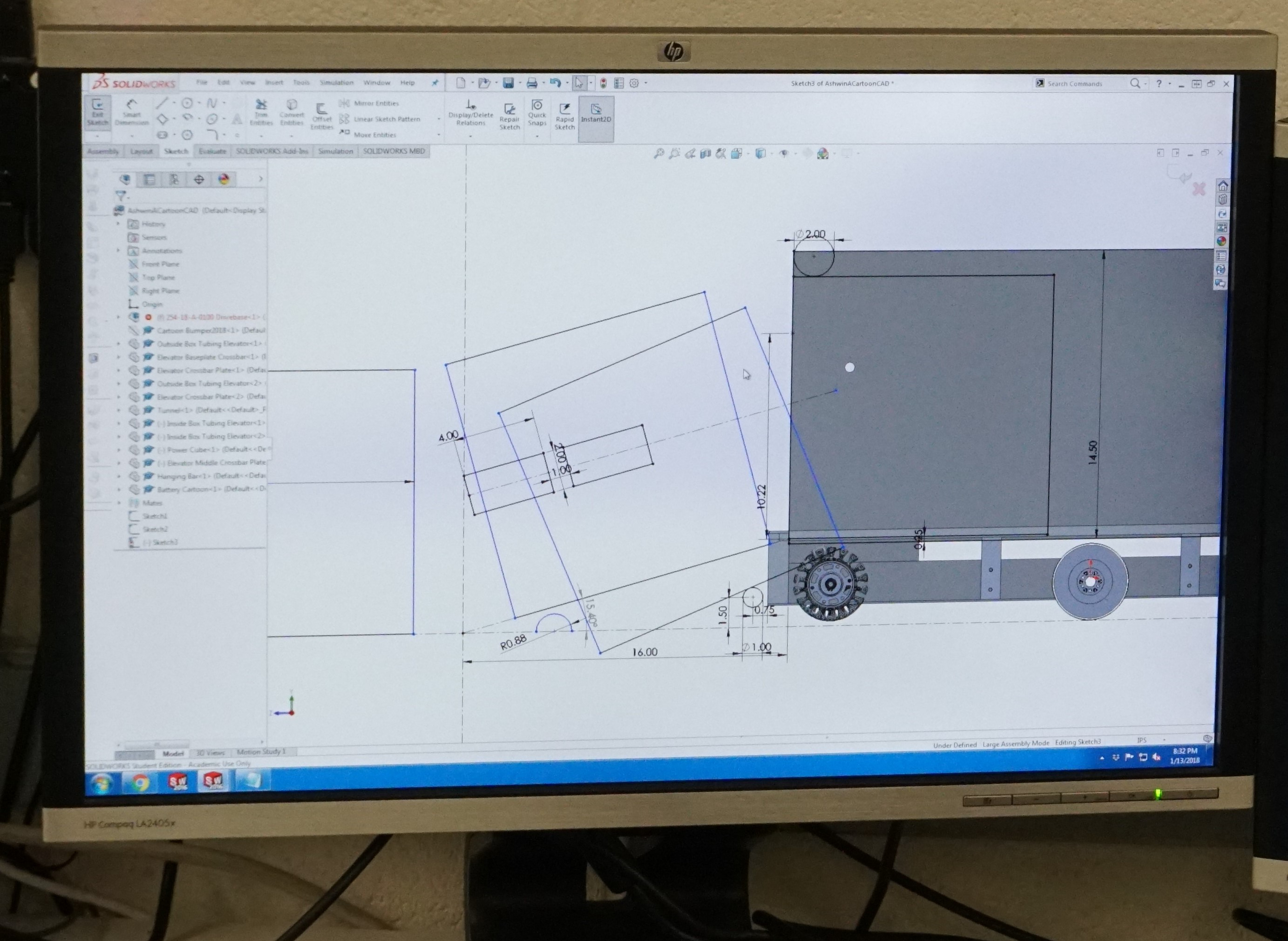
To ensure we have a stable robot when our CG raises with our elevator, we decided to extend our wheelbase as far out as possible. By doing so though, we are more susceptible to high centering on the platform ramp. To ensure we do not do so, we revisited the sketch we used to model the drivebase motion and adjusted the parameters to space the wheels as far out as possible and with a center drop. We also decided to constrain the lowest height of the bearing holes by having the center 16 tooth sprocket with chain OD be tangent to the baseplate. We will account for the chain run by having a cutout in our base plate.
Task: Finalize drive gearbox
-
We finalized the design of the drive gearbox and placed an order for the necessary hardware required (gears, pneumatics, screws, etc.) We hope to begin assembly of the drive gearbox this week.
Task: Sketch electronic placement
-
Task: Sketch electronic placement
We sketched the electronics placement on the baseplate. We plan on having the battery lay flat as in 2017 rather than standing up as in our 2016 robot. This way, we can lower the carriage/tunnel as far down as possible which means the cube does not need to move vertically as much from the ground to the handling mechanism.
Intake
Task: Prototype Intake
-
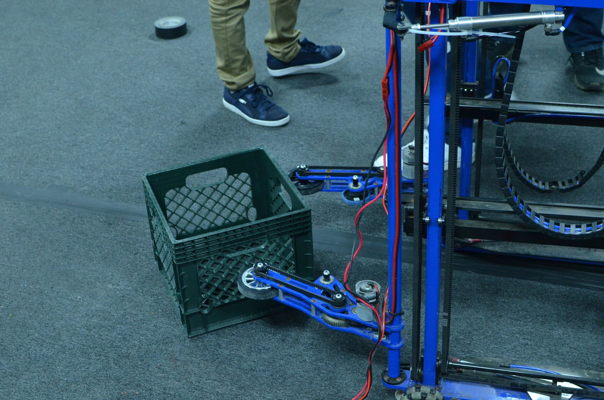
We assembled an intake with adjustable wheel placement and pivotable arms/outer wheels, and mounted it to the 2017 drivebase. We controlled each wheel with its own independent 775pro geared with a 5:1 reduction —- by doing so, we were able to test asymmetry and easily adjust certain speeds of certain wheels. This intake prototype worked well in quickly drawing in the cube and orienting it from a diamond to a square shape. We also saw that by increasing the pressure in the pistons controlling the outer arm pivot, the intake itself became a lot stiffer and was able to better control the cube. We quickly implemented a bottom kicker roller and saw that it worked well because the intake itself was able to provide enough force to push the cube up and above the kicker roller. Moving forward, we will design a prototype that combines this intake with a kicker roller and mount it on a test drivebase.
Task: Prototype ramp intake
-
We design and tested if a kicker roller + a ramp with wheels on either side guiding the cube up would work in transitioning the cube from the ground to the tunnel. While testing, we realized that the wheels on either side did not grip well to the cube (we used colsons) and the transition from the kicker roller to the ramp and wheels was not as straightforward as expected. When the cube goes over the kicker roller, its motion is not very controllable especially when that is the only roller it is contacting. We added a vertical constraint (a piece of 2×4) to stop the cube from being kicked too high, however it deflected the cube from the center of the intake and away from the ramp. Watch this video to see the prototype in action.
Miscellaneous CAD
Task: Cartoon CAD and system integration of robot
-
Today was mostly filled with discussion regarding how best to integrate the various systems of the robot and how to constraint the placement of those systems. In terms of the elevator, we will be moving the outer bars (2×1 box tubing) to sit on top of the frame rails. The outside face of the intermediate stage will come in 0.138" (same clearance used in 2011) from the inside face of the outer bars, and then the carriage tunnel will be another 0.138" in from the inside face of the intermediate stage. This leaves us with around 17" for the width of the tunnel which we think will be enough to handle any orientation of the cube. We also investigated the elevator placement with regards to climbing. To make climbing especially easy on the drivers, we plan on driving straight up onto the ramp and having our bumpers flush against the scale wall and our elevator bar flush against the 2×2 box hanger box tubing. With those constraints, this means our elevator sits 8" from the outside face of our bumper which also means that given we want to spit cubes out on the back side of the tunnel (the side opposite the intake), we need to spit them 8"+. 8"+ is not ideal especially if we want to strategically place a cube, so we need to further investigate how best to optimize elevator placement. We also did line contact calculations on the bearings contacting the intermediate stage from the outside bar, and given that we are hanging 3 robots, then the bearings as well as the aluminum tubing will endure more load than their static load capacity and yield strength, respectively, can handle, To solve this, we tossed around ideas of alleviating a portion of the load from the bearings with a tensile member extending from the top of the intermediate stage to the CG of our robot (the tension of the cable acts opposite to the torque of the robots). Lastly, we decided that to ensure we have a smooth transition from the intake to the tunnel, we will have the intake fixed to the tunnel and not pivot, but will have the entire tunnel + intake system pivot such that it can stow within the frame perimeter, intake horizontally, and place cubes on stacks on the scale.

Programming
Task: RPLIDAR Driver
-
We tested the driver that was already written, but nothing happened. After rewriting some of the code, we were able to send a request to the RPLidar and received some sort of "ok" response, but still, the RPLidar did not start scanning.
Task: RPLIDAR Data Visualizer
-
We worked on some more modifications to the visualizer. We were able to cache all the data sent to the visualizer in an array, so that we could view data with specific timestamps. We also worked on being able to zoom in and pan around the image of the field, so that it is easier to see, but there are still some bugs with this.
Task: Intake Prototype
-
For testing purposes, we remapped the control board so we could toggle each of the four motors on the intake prototype with four separate buttons on the driver station. We also added some buttons to change the speed of the motors on the intake. In addition, we read the drive code, but since last year's programming bot did not have a working compressor for the dog shifters on the drivebase, the robot could not drive.
Build Blog Day 4 (1/12/18)
Drivebase
Task: Test different wheel arrangements between colsons and omnis
-
We decided to switch our initial idea of using 6 colsons to 2 colsons and 4 omnis on the drivebase. We also decreased the drivebase width by 0.6 inches to accommodate for the entire width of the colsons. In addition, we added custom wheel shafts into the Drivebase CAD. We also added the gearboxes into the drivebase CAD. This will require us to change the placement of the electronic components.
Gearbox
Task: Design drivebase gearbox
-
We started by resolving a few minor issues with packaging Cims around the shifter cylinder. We also realized that we needed more space for components in our gearbox, so we decided to increase the size of the gears between the Cims to fit all necessary components. After fixing these issues, we now have a working gearbox design. At our next build, we plan to finalize the assembly and detail the Gearbox CAD.
Intake
Task: Design intake prototype with two horizontal rollers to pull in and kick up cube
-
We began build by testing the 1st simbotics style intake prototype with 2 sets of wheels. After our testing, our results confirmed that asymmetry is the best way to go forward. Next, we assembled a new intake prototype with a horizontal roller and a kicker roller placed slightly behind the horizontal roller. When testing this prototype, we noticed that the cube would be lifted off the ground and get stuck between the rollers. We plan to keep testing this prototype since the kicker roller showed some promise in getting the cube over the frame rail. Look at Video 1 and Video 2 to see this new intake prototype in action.
-
Lastly, we laser cut version 2 of the simbotics intake, which will be assembled during our next build.

Tunnel
Task: Design tunnel with timing belts to drive the cube across on all four sides
-
The original plan for the tunnel was to have a square tunnel 13”x13” that would have power belts on each side. This way, no matter the orientation of the cube, it would always be in contact with at least 3 sides.
Programming
Task: Test the lidar driver with the roboRIO
-
We worked on the driver, which helps us get data from the RP LIDAR sensor. The sensor gives the distance in mm and the angle in degrees of a detected object.
Task: Hook up the visualizer to the robot
-
We also worked on the visualizer by plotting dummy points on a picture of the field. We encountered a few bugs, but fixed them all. Look below for a picture of the visualizer.
Task: Setup and testing
-
Limelight is a camera specifically made for FRC, which makes it easier to use, so we have been experimenting with it. We tuned the vision pipeline specifically for the power cube. In this process, we realized that we had to re-tune the vision pipeline in different lightings, so at each competition we would have to re-tune the pipeline if we were to use the Limelight. The Vision Pipeline is a set of consecutive image processing functions that work to isolate and find specific objects.
Build Blog Days 2 and 3 (1/8/18 – 1/10/18)
Drivebase
Task: Test drivebase with modelled dimensions (28"x33") 1.15” center drop; from top of frame rail and placed 2.5” from the front and back of the drivebase frame high centering on the ramp at various angles.
-
When approaching the ramp perpendicularly, the robot clears the ramp and does not high center. However, when it approaches at angle towards the corner of the platform where the front and side ramps meet, it high centers. Also, when the robot is travelling up the ramp with the cable protector below it, The back of the drivebase frame contacts the cable protector and high centers on it. The drivebase modelled with these dimensions in CAD accounts for a 16 tooth sprocket with chain OD and a 0.1" clearance between the sprocket-chain OD and the baseplate. In addition, the 4" colson wheels used are actually 3.9" wheels. If we were to bring the sprocket lower to the baseplate and use fully 4" wheels, there is a possibility it would not high center. We need to investigate the lowest we can go with the sprocket-chain OD and test with new 4" wheels. Additionally, these results may change our driving strategy where we will only attempt to go up the ramp perpendicularly. See these videos to see the drivebase in action.
Task: CAD drivebase weldment and begin work on drivebase assembly
-
We designed the drivebase frame rails such that the wheel placement and center drop can be easily modified as they are yet to be finalized. We went with our traditional West Coast Drive using 4” colson wheels. Assuming we will want to carry our partners while climbing, we need to beef up our drivebase, whether it be using thicker box tubing or by adding cross members. We will perform a bending calculation on different sizes of box tubing to determine what is the best size to use. Regarding bumper mounts, we currently see to ways to approach the task. The first way is a 2014 style bumper mount with latches on the drivebase frame that latch onto mounts on the bumper. The second way is a 2017 style bumper mount that uses guiding rods that go into the drivebase frame and some other latching system. The 2017 is definitely a harder bumper mount to work with, however, the straight face with mounting provisions may prove useful if we decide to deploy ramps for our partners to climb up on. We will investigate this in a cartoon CAD.
Task: Drivetrain gearbox design
-
We decided on a triangular configuration of mini-CIMS, with ratios that yield about 10ft/s and 18.6 ft/s. We are now trying to figure out how to package the shifter cylinder into the gearbox below the CIMs. We are exploring either a smaller bore cylinder or a nose-mount piston instead of pancake. Changing from 3/4 to 9/16 bore reduces the shifting force from 22lb to 11lb; Further testing is needed to see if this is enough force to shift. Regular air cylinders can be used if it is ok that they stick out longer than the CIMs. The next steps are to finalize which shifter cylinder we want to use, model the rest of the gearbox plate, and then detail in the entire gearbox assembly with Cheesy Parts.
Intake
Task: Test intake prototype with pivotable arm
-
We assembled the intake prototype and mounted it to the 2015 drivebase to test. We were able to run a few tests with a single set of wheels, but unfortunately, as the intake was made out of 0.25" plywood, a part of the arm broke off and we were unable to gather any further data.
Task: Test 2015 Simbotics style intake prototype with pivot wheel sets
-
We initially based the intake prototype off of 2015 Simbotics’; with the first set of wheels pivotable but not the second set–we spaced out the second set to be tangent to the cube when it is 13" width. When intaking a cube in a square position, the intake easily worked, however, when intaking a cube in a diamond position, the cube got trapped between the first set of wheels which were able to pivot to comply to the cube's shape and second set of wheels which were stationary. To fix this, we made the second set also pivotable and were able to intake a cube at different angles. We hooked up the motors on the intake to the drive talons on the development board and were able to simulate different speeds for different sides by turning with the control board joysticks. With different speeds, we were able to force the cube to rotate into a square position in a certain direction which shows that some amount of asymmetry may be necessary to intake cubes. We will continue testing this intake on the field carpet to account for the friction between the cube and field and will further design this in CAD into a stronger prototype.
Programming
Task: RPILIDAR Driver
-
We finished up writing the driver and implementing all necessary methods. The driver is ready to be tested once the LIDAR sensor arrives.
Task: LIDAR Visualizer
-
We continued work on the LIDAR visualizer. We set up a Node JS server that recieves LIDAR point data encoded in JSON from the roboRIO using Network Tables. The server then uses websockets to send this information over to the viewing page. We also continued work on the visualizer interface. It can now plot fake JSON data, but needs to be hooked up the the websocket so it can display a continuous stream of data from the LIDAR sensor.
FRC Build Blog Day 1 (1/6/2018)
Here is the 2018 game animation.
Game Analysis
This year’s game involved many variables, requiring a strategy that succeeded in performing all tasks presented in the challenge. With the power ups, scoring based on points/sec, randomized sides, and the difficulty of climbing, no straightforward strategy which ensures a win presents itself. After trying various combinations of scores, we concluded the best way to maximize our points would be during autonomous when the scoring is scaled by a factor of 2 and during the endgame when each climb is worth 30 points. Since autonomous scoring is worth more than tele-op scoring, we decided that autonomous scoring was a major priority to stay ahead during a match. We planned for short paths to score cubes (<30 ft), so drivetrain acceleration and our ability to score from either side of the robot was critical for rapid cycles. We debated between starting off on the middle or side of the field. If we were to start off on the middle, we would have an equally distant route to reach the switch and scale. However, we could not guarantee the successful completion of our autonomous route as our alliance partners may get in our way. If we were to start on the side, we may either have a very long or a very short route to reach the switch and scale. However, we could guarantee the successful completion of our autonomous route as our alliance partners would not get in our way. During the endgame, we aimed for having all 3 robots climb or by having 2 robots climb and 1 levitate.
Drivebase
Task: Fix 2015 drivebase and prototype if it can go over the platform ramp
- We fixed the 2015 drivebase which was missing a control system. We mounted our development board on the drivebase and programmed it to drive, but immediately saw issues as it went up the ramp. Because of the long wheel base and short distance between the wheels and the ground, the drivebase high centered on the ramp when the bellypan came into contact with it. This result shows that for our 2018 drivebase, we will need a shorter wheelbase and a greater centerdrop.
Task: Model drivebase motion up the platform ramp
- We modelled in CAD the motion of a possible 2018 drivebase going over the platform ramp without high centering. We tweaked two factors (distance of outer wheels from side edge of frame rail, center drop) until we arrived with the dimensions of a drivebase that would safely clear the ramp with 4 wheels (2 on each side) always contacting it and without the bumpers or bellypan ever contacting it.
Intake
Task: Fix 2015 intake and prototype if it can intake Power Cubes
- We fixed the 2015 intake which was initially missing the intake wheels, shafts, and timing belts. We used this intake to prototype the intaking of the Power Cubes. We did see some promise with this intake, however since it was designed for the tote and not the Power Cube dimensions, we were not able to efficiently intake the Power Cube. Moving forward, we plan on testing out different wheel materials to contact the Power Cube as it is being intaked and will design/prototype an intake with the correct geometry to fit the width of the Power Cube.
Field Prototyping
Task: Test coefficient of friction of Power Cube on scale plate
- We wanted to calculate the coefficient of kinetic friction between the Textured HDPE and the fabric of the Power Cubes. To do this we looked at how high we had to lift the straight piece of HDPE before the Power Cube started to slide down. From this we calculated the angle formed and the coefficient of kinetic friction which ended up averaging to about 10.32 degrees and 0.18, respectively.
Task: Test geometry of 3 robots on the platform
- We laid out the spacing of three robots on the scale platform to see if it was physically feasible of having 3 robots side by side with enough space for the robots to maneuver to those locations. It seems that it is possible for 3 robots to fit on the platform.
Task: Find what angle does the scale tilt to at its highest state
- At its highest state, the scale tilts to around an angle of 7.662 degrees. Based on our data gathered from the task: “Test coefficient of friction of Power Cube on scale plate”, the Power Cubes will not slide down the scale plate when it is tilted to its highest state.
Field Construction
Task: Assemble wooden scale
- We assembled a wooden version of the scale, however we are planning on assembling an aluminum version similar to the scale we will see in competition. This is because we don’t want any differences from the tournament scale from different materials that will arise in different materials (center of mass, weight, friction) which may impact our robot performance and drive our robot design.
CAD
Task: Space claim of 3 robots on the scale platform
- In CAD, we made a space claim of 3 robots, placed them in various arrangements on the scale platform, and looked at the feasibility of having all 3 side by side. It seems that it is possible for 3 robots to fit on the platform.
Programming
Task: Program 2015 drivebase to steer in correct direction with controller joysticks
- When we initially placed the development board control system on the 2015 robot and attempted to drive it, the wheels were turning in the opposite direction to the controller joysticks. We corrected this by reprogramming the drivebase to match with the direction of the controller joysticks.
Game Analysis, Scouting, and Strategy Workshop
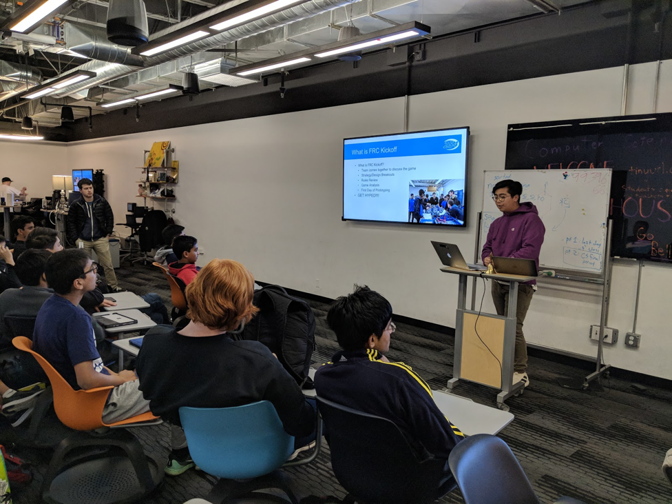
On Thursday, December 7th, we hosted a Game Analysis, Scouting, and Strategy Workshop to help acquaint new team members with an important aspect of the robot game. The workshop by led by a member of Team 254’s drive team, Brandon Chuang. During the workshop, we taught new members about the importance of pit scouting and match scouting and how we use the data that we collect in order to form great alliances. In order to give our members a realistic experience, we helped them analyze a 2016 FRC Match Video and track the number of points scored by each team during the autonomous and teleoperated periods. Members were introduced to the team’s scouting database and how it is used at tournaments to organize collected data. Our drive coach, Kevin Sheridan, and FRC Technical Lead, Ashwin Adulla, also helped provide examples of some hardships that Team 254 went through when forming alliances at tournaments. We also emphasized the importance of working together with other teams and how that plays a role in an alliance’s performance. Overall, we strategically prepared our new members for kickoff!
Discovery Day 2017
Event Summary
On November 11th, Team 254 appeared at the Bay Area Science Festival Discovery Day to demonstrate our 2017 season robot Misfire. At the event, we used a few game elements like wiffle balls, gears, and a makeshift wooden hopper to show over 2000 people the capabilities of our robot. In addition, we spoke about our experiences during 2017 FRC season and the challenges we faced. We collaborated with other FRC teams including Team 1868: The Space Cookies and Team 5026: The Iron Panthers to convey the message of FIRST and STEM. This event allowed us to spread our knowledge and experience to our community in the Bay Area.
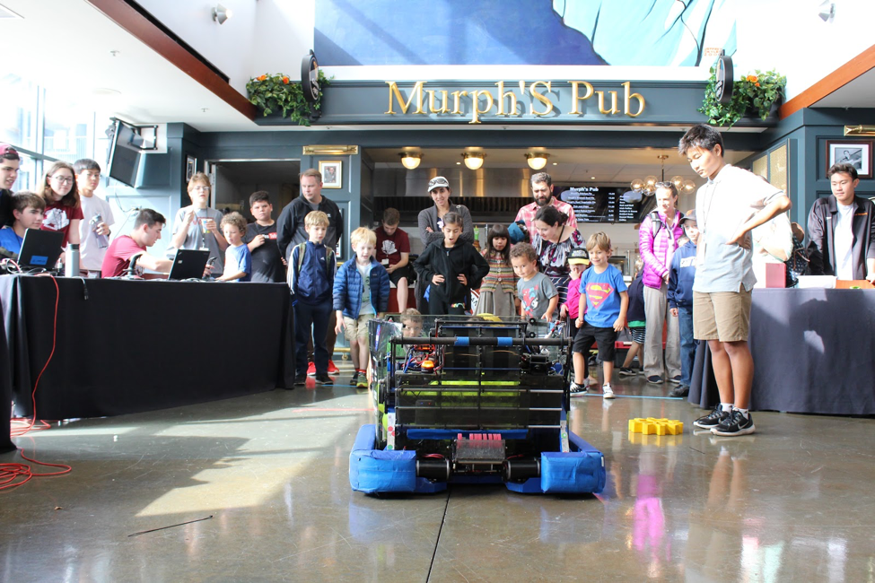
Team 254 Members showcase Misfire to the audience
Our Experiences
Our experience at Discovery Day not only spread awareness for STEM within our community, but also made an impact on our team. Outreach leader, Yusuf Halabi stated, “My Discovery Day experience this year allowed me to take a new perspective into 254 and our role as an organization. When I first joined robotics as a freshman, I was under the impression that 254 was only good for creating robots. However, my experience at Discovery Day allowed me to realize that serving and supporting the community is just as important as building robots.” Similarly, Team 254 Operator, Themis Hadjiioannou said, “My favorite part of Discovery Day was seeing the joy on children’s’ faces when they saw Misfire shoot into the high boiler. Watching the light in their eyes flash as they observed what a robotics team was capable of struck a chord with me. I thought back to when I was a kid and was inspired by drones and robotics. Discovery Day made me proud to be a part of an organization that strives to bring this inspiration to kids around the world.” Overall, Discovery Day was an outstanding outreach event and we wish to continue making such a profound impact in our community!
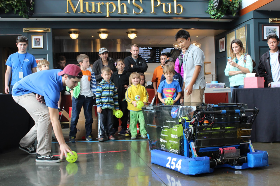
Team 254 Driver, Justin Ramirez, helps load up fuel before Misfire demonstrates its shooter
2017 Winners of Chezy Champs!
A Brief Summary
As part of an eventful weekend, we hosted Chezy Champs, our annually hosted offseason FRC tournament at Bellarmine College Preparatory, in our hometown of San Jose, CA. We had a great time jumping back into action with our robot, Misfire, before the start of the 2018 FRC Season. Alongside, FRC Team 1011 Team CRUSH, FRC Team 696, Circuit Breakers, and FRC Team 5104 BreakerBots, we were able to win the tournament!
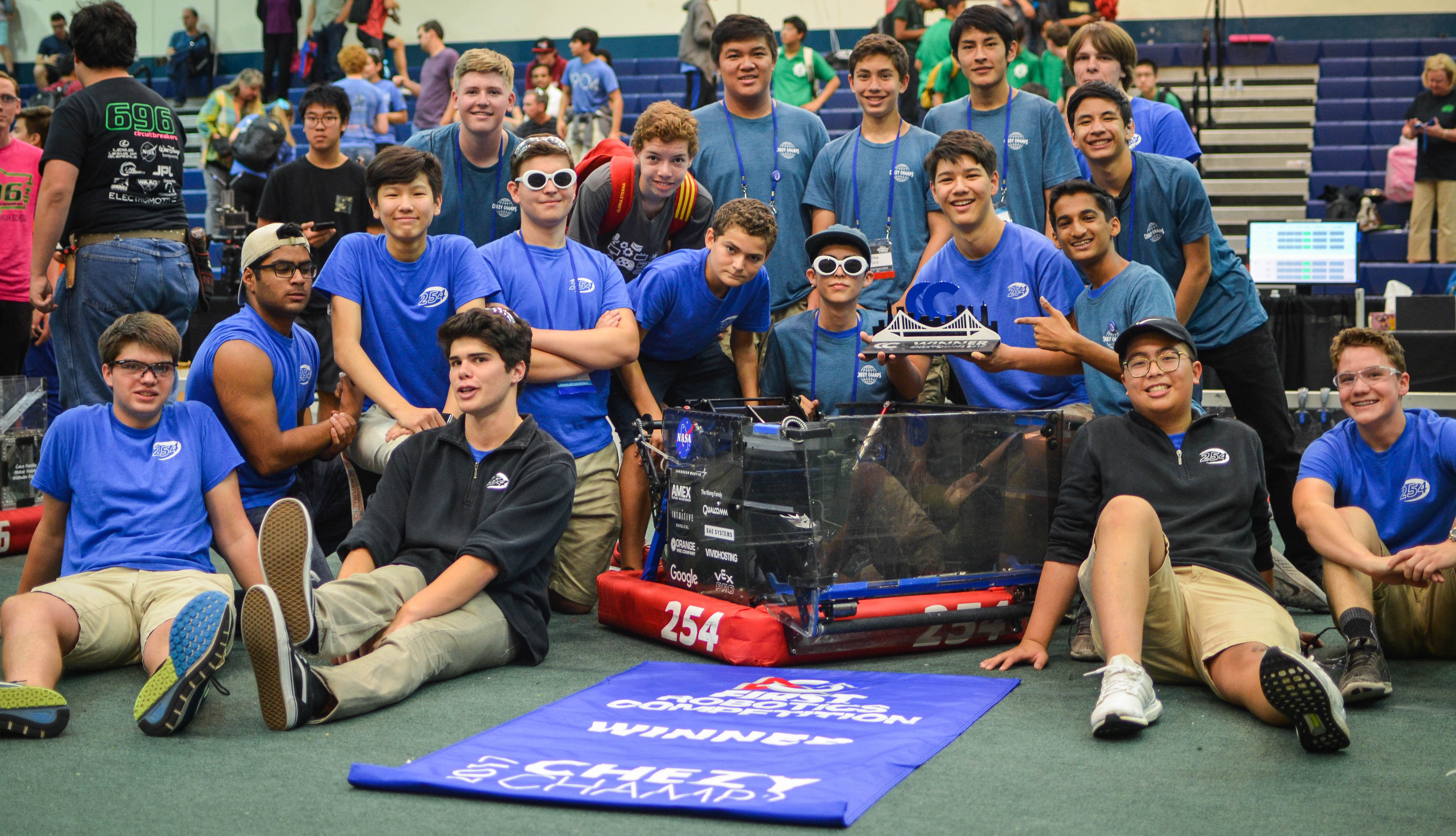
Team 254 Members pose for a picture with Misfire after winning at Chezy Champs 2017
Event Highlights
General Highlights
Check out this great highlight reel made by RoboSports Network (RSN)!
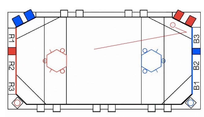
Exhibition Match
At the tournament, we hosted an exhilarating exhibition match, which included the several teams with highly skilled shooting robots. The standard rule for this match was that the only way to score points was to shoot fuel into each alliance’s respective boiler. The teams which participated in the exhibition match:
The Blue Alliance
- Team 971 Spartan Robotics
- Team 973 Greybots
- Team 1678 Citrus Circuits
The Red Alliance
- Team 254 The Cheesy Poofs
- Team 1323 Madtown Robotics
- Team 3309 Friarbots
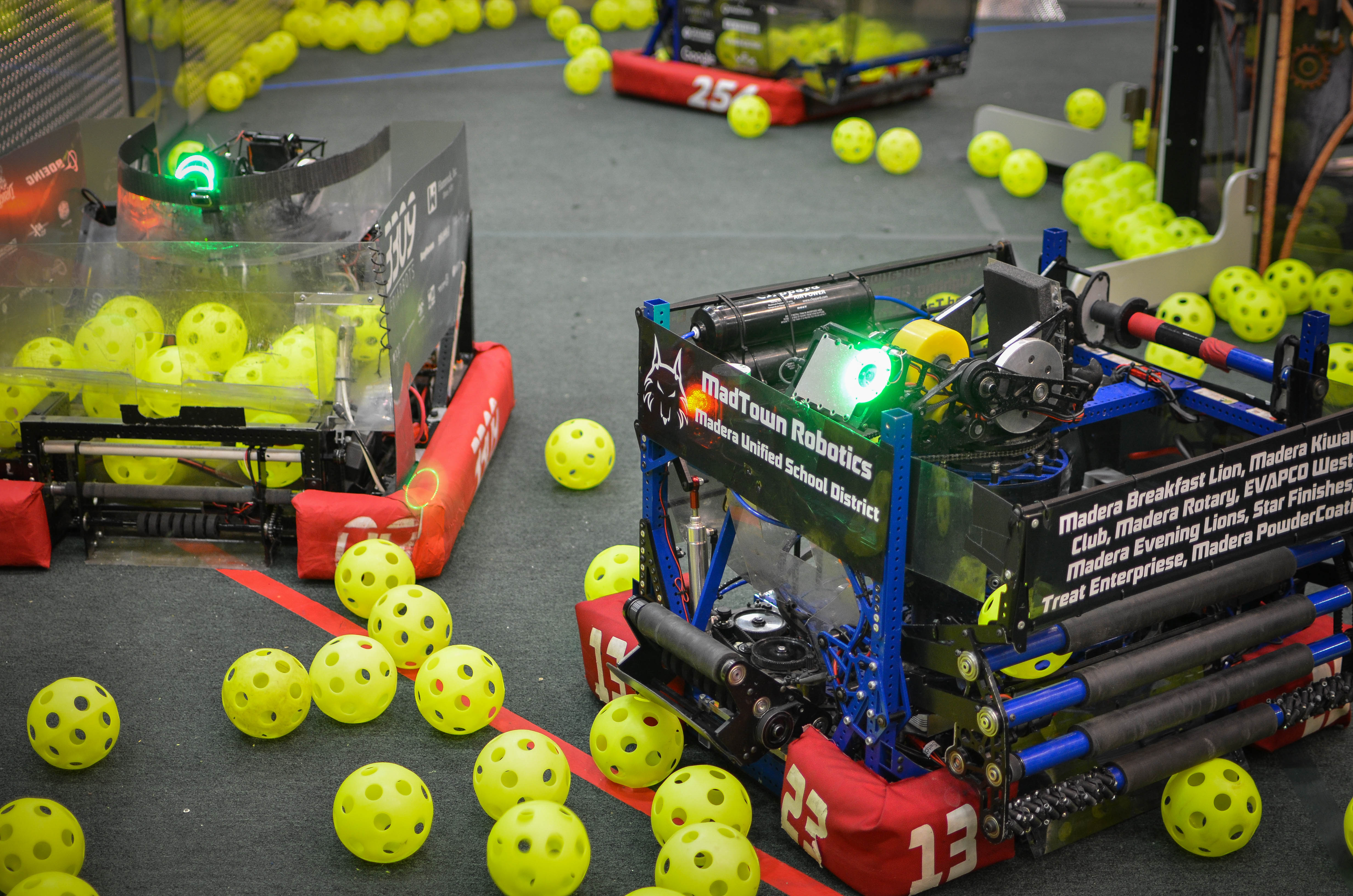
Team 1323, Team 3309, and Team 254 work together to gather fuel to shoot into the boiler
The Red Alliance started off with a significant lead by scoring 50 fuel balls into the boiler, making it an amazing show for the audience to see 3 robots scoring fuel into one boiler at once! Eventually, the Blue Alliance slowly started catching up with the Red Alliance by consistently scoring their collected fuel into their boiler. With a minute left in the match, the our friends from Team 973 displayed their true defensive skill by blocking Team 1323’s path across the field. Though the Blue Alliance’s efforts were equal to that of the Red Alliance, the Blue Alliance was unable to keep up with the pace of the Red Alliance. After the great efforts shown by both alliances, the Red Alliance came out to be the winner scoring 203 kPa compared to the 97 kPa scored by the Blue alliance. The Exhibition Match Video can be viewed here.
A Special Thanks
Chezy Champs was very special this year due to the efforts of so many people and organizations. Team 254 would like to thank our friends from RoboSports Network (RSN) for providing our audience with such a great analysis of each match and team at the tournament. We would also like to thank all the volunteers, who helped make Chezy Champs possible. It was truly an incredible experience to host an offseason tournament attended by so many talented teams, even those who chose to attend from out of state, and to make new friends and catch up with old ones too!
Robot Performance
Throughout the qualification matches, we encountered a few mechanical problems with our gear grabber, hopper, and drivetrain and a few problems with Misfire’s autonomous performance. After some careful observation, we realized that our gear grabber’s knife-edge was worn out, so we replaced it with a new piece of polycarb. Our stationary hopper panel kept colliding with the field hoppers, which tore our hopper wall. We replaced the broken hopper panel to solve this problem. We also noticed a crimp lodged between our chain and sprocket on our drivetrain, so we removed it to make our drivetrain function normally. Overtime, our autonomous performance improved after our mechanical changes. Thus, we were able to seed first for alliance selection after having a qualification match record of 7 wins and 3 losses.
Misfire successfully hangs within the last few seconds of a Qualification Match
During elims, we faced some fierce competition during our Semifinal and Final Matches. We ended up having to compete in a third tiebreaker match in semifinals and finals. In Semifinals Match 2, the opposing alliance of Team 973 Greybots, Team 1538 The Holy Cows, Team 604 Quixilver, and Team 2135 Presentation Invasion, scored a large amount of kPa during auton and kept their lead up by activating all 4 rotors! In Finals Match 2, the opposing alliance of Team 1323 Madtown Robotics, Team 3309 Friarbots, Team 5026 Iron Panthers, and Team 2073 EagleForce, displayed their true skill, by keeping a consistent lead, from the start of the match. By the end of our elimination matches, we won all of our tie breaking matches, allowing us to win the event with our alliance. We wouldn’t have been able to accomplish such a victory if it weren’t for our amazing alliance partners – Team 1011 CRUSH, Team 696 Circuit Breakers, and Team 5104 BreakerBots.
Members of the Team 254 Pit Crew repair Misfire before an upcoming Finals Match
Festival of Champions
2017 FRC Class of FIRST Champions
Recently, we attended the first ever FIRST Festival of Champions in Manchester, NH. After winning the St. Louis Championship with our extraordinary alliance partners, we faced the Houston Championship winning alliance in an intense series of 5 matches. Alongside Team 2767 Stryke Force, Team 862 Lightning Robotics, and Team 1676 The Pascack PI-oneers, we were able to win the Festival of Champions Event. We enjoyed a tour of DEKA and a great potluck at Dean Kamen’s home. We would like to say thank you to FIRST for giving us the amazing opportunity to participate in this event!
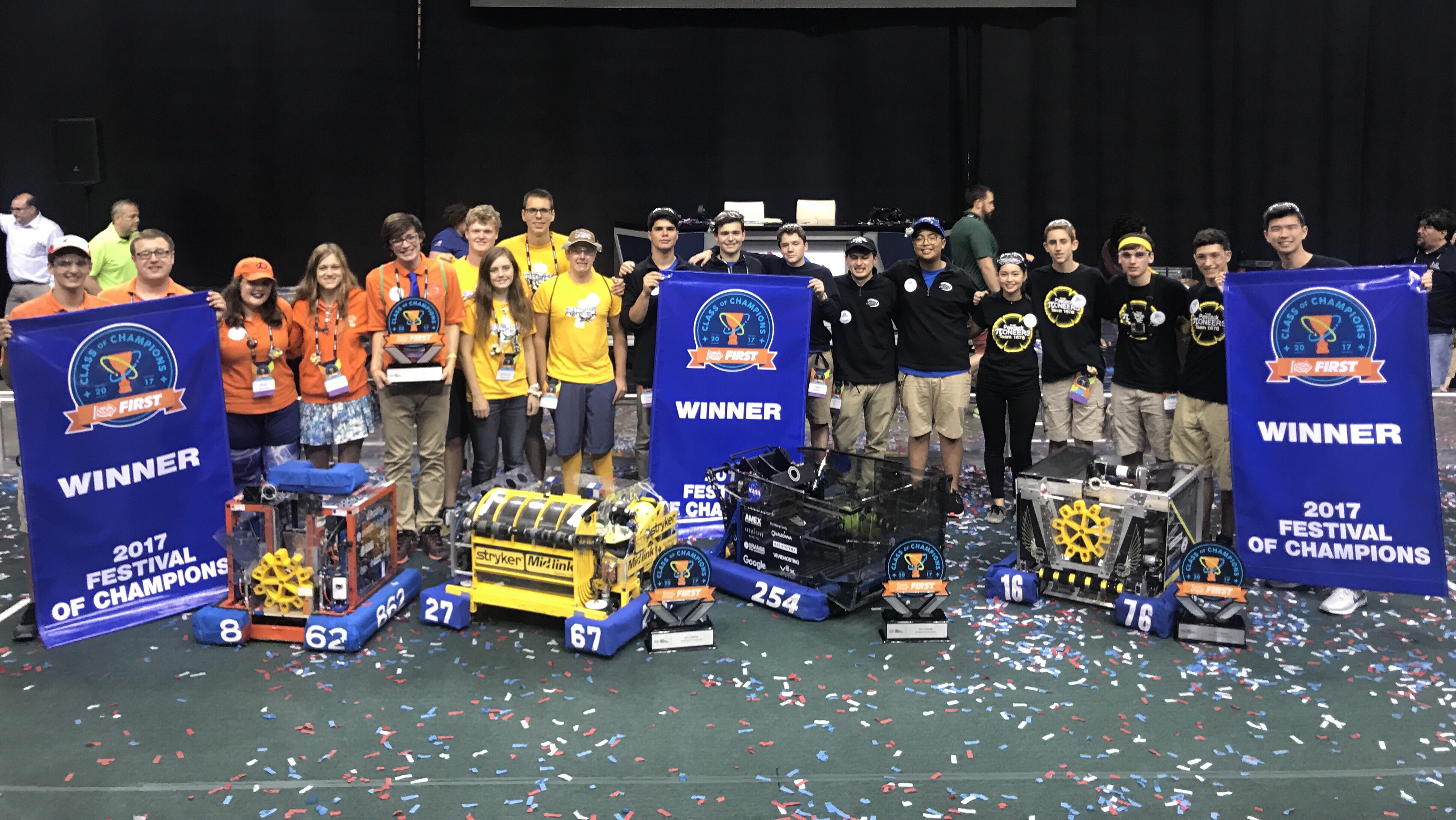
“Thanks to the phenomenal performance by our alliance partners!”
Championship Matches
In the most intense games we’ve played all season, the Houston alliance won the first two matches. Our alliance won the third and fourth to stay in the game. In Match 4, our alliance partners helped us win against the Houston alliance by a margin of only 16 points. In the final match, our alliance capped a great season with one last win. We won the match, and the festival championship, setting a record high score for this year’s game of 588. We’ll let the video speak for itself, as our last finals match was certainly one of Team 254’s best performance of the season.
We would like to honor our alliance partners because of how far we all came, from St. Louis to Festival of Champions. We would also like to thank Team 973 Greybots, Team 5499 The Bay Orangutans, Team 1011 CRUSH, and Team 2928 Viking Robotics from the Houston Alliance for setting the bar high and making all our matches an intense, and great experience. We’re excited to meet other FRC teams at our annual offseason event, Chezy Champs, and to kick off next year’s season!
FRC Day 42 Build Blog
Day 42: Preparing for World Championships
Quick Summary
Everything that we need at competition, which includes the pit, was packed and prepared for being shipped to St. Louis.
Robot Progress
Shooter
We worked on some hood geometry and started to look at the placement of the hanger tube and different sizes. We also finished the design of the new hood and CNCed the new hood plates. We laser-cut a new center divider for the hood. Everything was assembled at on Monday’s build.
Hopper/Intake Ramp
The old hopper broke on the practice bot, so we laser cut new plates and assembled them onto the robot. We also cut spare hopper plates and spare intake ramps in case we need them during champs.
Driver Practice
We started practicing a new kind of gear cycle called the check mark cycle, which we plan will probably use from here on out.
Programming
Today, we worked on shooter tuning and semi-automated gear placement in teleop using an ultrasonic sensor. For shooter tuning, we worked on fixing a problem where our stream will begin to walk backwards over long periods of time. We believe this is a result of the system becoming more efficient over time as the bearings on our flywheel heat up. To solve this problem, we tried compensating for the increased flywheel speed over time by taking an average speed of the flywheel between shots and using it to adjust our voltage.. For teleop gear placement, we tried to use the ultrasonic sensor to limit the amount the robot can drive backwards when scoring gears to prevent it from driving too far back and bending the spring. However, we found that the ultrasonic sensor updates far too slowly for this to actually work right now, so we are investigating ways to speed up the ultrasonic sensor and use our drivebase encoders to compensate for this lag.
FRC Day 41 Build Blog
Day 41: Improving Gear Scoring
Gear Grabber
Today we worked on the Cow Catcher, or an assembly that prevents balls from getting stuck in the Gear Grabber and pushes balls out of the way. We began with prototyping with two delrin side plates and a 3/8" standoff, and while the results were promising, balls still got caught in the general vicinity, affecting its performance. To solve this issue, we prototyped the cow catcher with a longer standoff, which prevented balls from getting caught.
Having determined the relative effectiveness of the Gear Grabber, we began to design a deployment mechanism such that the cow catcher fits in the framer perimeter at the start of the match. We came up with the use of a torsion spring and hardstop to deploy the cow catcher at the start of the match. Due to the limited availability of springs at the lab, we used rubber bands instead, but the deployable cow catcher was ultimately too weak. Thus, we added standoffs and reinforcing plates to increase rigidity.
Robot Progress
We worked on fixing up our practice bot, making a new intake ramp and straightening out our hopper flanges. We also did a lot of shooter testing and were able to significantly improve the accuracy of our shots.
FRC Day 40 Build Blog
Day 40: Improvements for SVR
Driving Improvements
We added additions to our robot in order to create an easier and more efficient driving environment. We have placed a blue LED strip on the back of the hood to let drivers know whether or not they are in a good shooting proximity. To do so, we wired up MOSFETS to control the LED strip, which will plug into the DIO port on the roborio.
CamerasfAutono
At SFR, we found that installing “back-up cameras” would help with gear placement. Therefore, we worked on optimizing the camera placement, as well as finding a way to widen the narrow field of view (currently 70 degrees) to better capture the gear’s location.
Autonomous
After the post-mortem we worked to improve the robot's turning during autonomous. We prototyped small Delrin sliders that didn't quite work when sliding on carpet. We anticipate that the best solution will be to try to implement drop-down omni wheels that we can turn on. However, if that does not work either we will resort to changing the autonomous routine itself.
FRC Day 37-39 Build Blog: Preparing for Competition
Days 37, 38, & 39: Preparing For Competition
Intake
Today, we worked on fixing the intake after it broke earlier this week. After analyzing the strength of our current weldment and modifying it slightly, we decided that simply strengthening it would not help the fundamental problems existing in the design. We took one of the broken intakes and attached it to new polycarb side plates hoping that this would decrease impact forces by increasing the time of impact (change in momentum = force * time). We drove around and crashed the intake several times with minimal damage occurring, and we are proceeding with the new design.
Hopper
Today, we worked on the Hopper and testing the fully assembled redesign. After fixing some initial discrepancies in the real life assembly, we tested out deployment and stowing. As of a few tests, the intake deployed well (after modifying the intake ramp slightly to have slightly deeper notches to fit the constraint screws in) and we will be updating the CAD with these changes on Friday. We will also laser cut a new intake ramp to get definitive results. If all systems work well after that, we will begin assembling the new parts for comp as well as a back up.
Between, Friday and Saturday, we were able to finalize the hopper design. After some CAD work on the redesign and some troubleshooting after assembly, we were able to make a solid hopper. More testing will continue to confirm consistency, but we will be moving forward with the Comp set soon.
Shooter Flywheel
In the last week, we explored the use of a large flywheel to help increase the consistency of the shooter. A flywheel dramatically increases the kinetic energy of the shooter wheel system, hopefully reducing the amount that the wheel slows between shots. We designed a steel flywheel with about 4 lb*in2 of inertia. It is geared up 2.5:1 from the shooter wheel to increase the kinetic energy. Preliminary testing shows that adding the flywheel may not actually achieve the desired result. The elasticity of the timing belt caused some controllability challenges that the programming team worked on this weekend. Each time the direction of tension in the belt switched (from energy going into the flywheel to energy leaving the flywheel), there was a little bit of elastic movement which added oscillations to the shooter wheel system. The plots looked like the typical mass/spring/damper plots for a 2nd order system from a controls or dynamics class.
 Climber
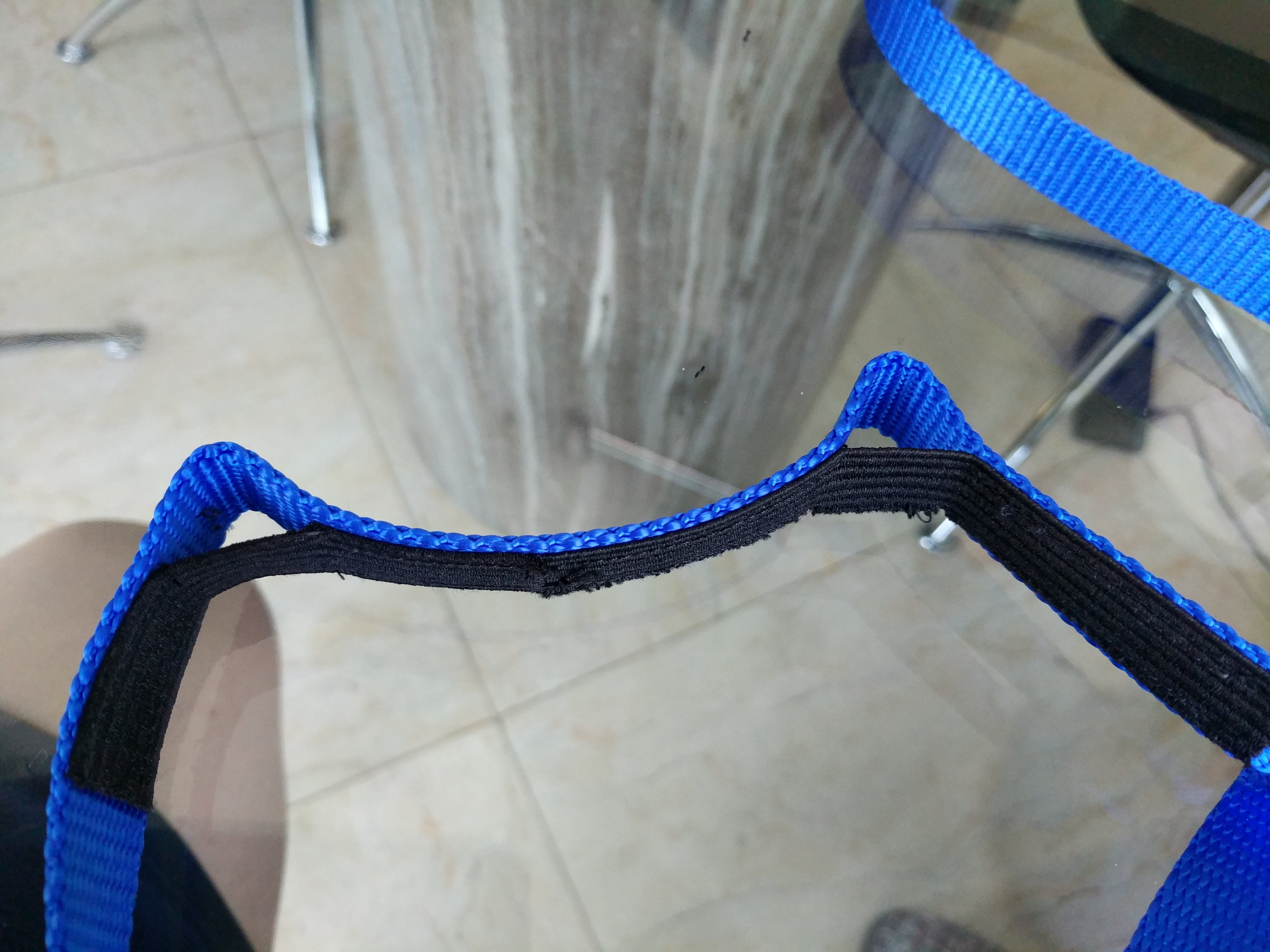
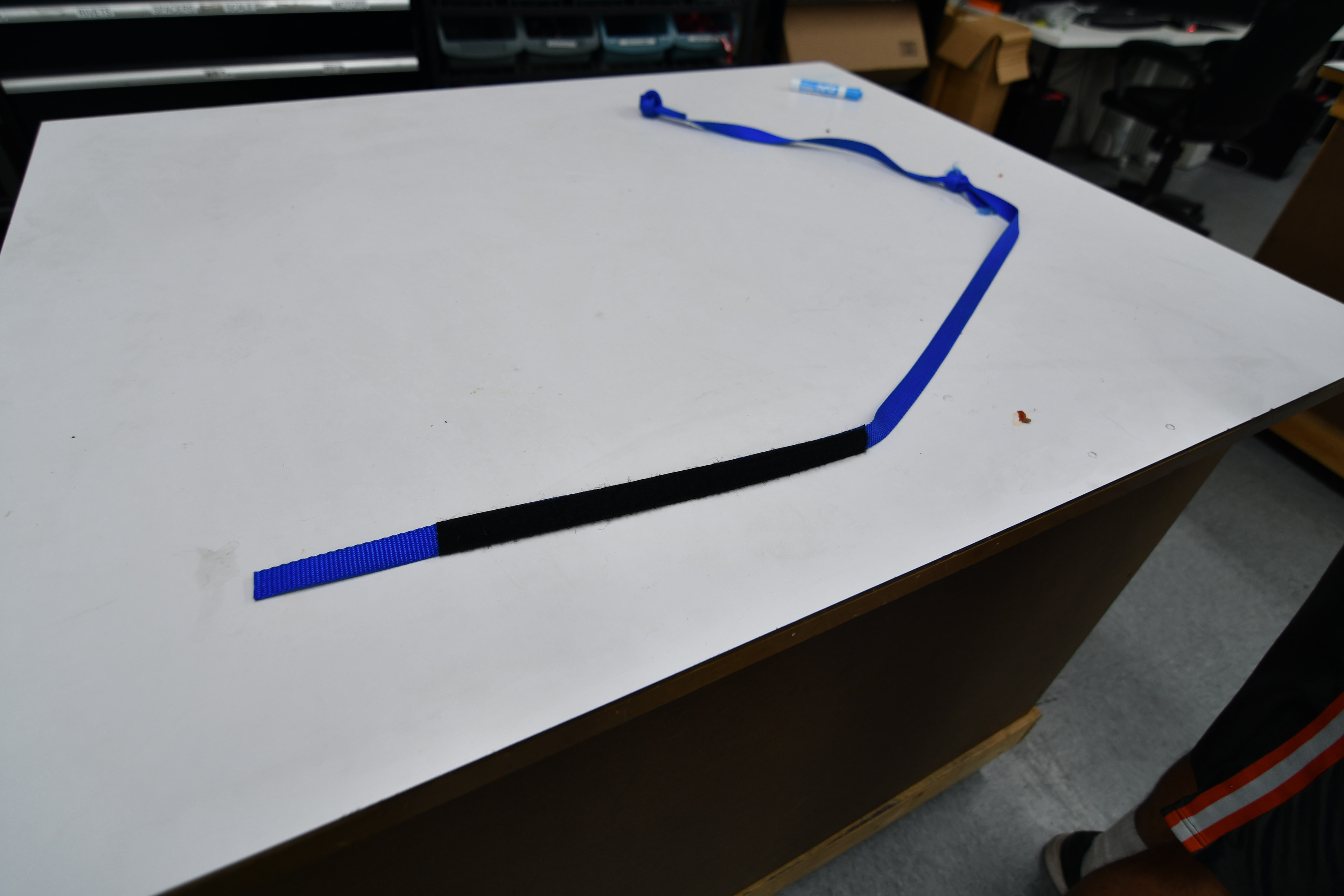
We are using inline elastic to add stretch to the rope. This will allow the robot to pull the rope down with a low amount of force at first, getting some wrap before beginning to lift the robot off the ground. This is important because the Velcro that engages the climber drum is strong in shear – and its strength is proportional to surface area. Once the rope has wrapped around the drum enough, the load transfer switches to Capstan forces. We are assembling several ropes, each with a number of pockets like the ones shown below.
A video is linked below of the climber being tested. Note that in this test case, we were pulsing the motors. Typically, the climb is much faster.
Gear Grabber
The latest iteration of the gear grabber has a dual pivot design – the whole mechanism pivots from a pickup configuration to a scoring configuration with one pivot, and a second lower pivot is sprung to allow the wedge to conform to the floor without digging in. We built this prototype last week out of delrin on the laser cutter and used it for driver practice over the weekend. We moved forward with making this out of metal and sent the parts to Anodize on Monday morning.
Check out the video below for pickup and scoring performance of the current prototype:
Driver Practice
We practiced driving by cycling gears with and without defense, climbing, and intaking balls off the floor. We are much better now at quickly scoring gears, and in one practice match we scored 9 gears and climbed when no defense was played on us. The gear grabber is much more reliable, and consistently picks up gears off the ground the second we touch them. Scoring is still tricky, but we are getting better at finding the right depth at which we need to drive into the spring.
Programming
Autonomous Program
Today, we worked on finding and fixing a bug in our Adaptive Pure Pursuit controller. The bug was causing arc lengths in the controller to be calculated incorrectly in some cases, resulting in a value much higher than it should have been. This would in turn cause the robot to drive way too fast and shoot past the end point in the path.
Gear Grabber State Machine
Today, we worked on implementing a new Gear Grabber state machine. The new gear grabber code greatly simplifies the operator controls. Now, there are only 2 buttons used for intake and release. The state machine uses output current to determine when a gear has been picked up and will activate the piston automatically.
More Information
We also found two bugs resulting in the robot not turning left and twisting along an autonomous routine, and we were able to fix these edge cases.
The hardware team began crimping and attaching 15 battery leads and running battery tests to determine true battery capacity.
FRC Day 36 Build Blog
Day 36: Improving Subsystems
Hopper Floor
Today we ordered all the the parts for the upper extension of the hopper floor and got majority of the CAD done. We will be going with 50 degree edges made out of Delrin with the first two rollers of the upper extension not having any surgical tubing to allow for horizontal movement.
Feeder
Today we worked on inventorying all the COTS parts for the Feeder subsystem. This would allow us to become more organized and make sure parts we need we have or are buying. I also helped lead students in inventorying other subsystems via the CAD,
Gear Grabber
We worked on the gear grabber. We removed the polyurethane added before with black, conforming WCP wheels. We found them to work significantly better than the polyurethane, but still not extremely well. We continued to work and changed the WCP wheels to red conforming wheels, which while ugly, worked better.
FRC Day 33, 34, & 35 Build Blog
Days 33, 34, & 35: Preparing for Competition
Gear Grabber/Driver Practice
We worked with the drivers over the weekend, doing basic drills like gear cycling, in order to become accustomed to driving the robot prior to the SFR Competition. We started the day by iterating on the floor for the gear grabber. The floor pickup for gears still needs work as it is inconsistent at picking up the gears when we drive into them. The polycarbonate knife edge was not as smooth as the prototype. There was a small edge on the actual version which was causing problems, so we sharpened it. After iterating on it, we then mounted it, and set ourselves on solving the jackknifing. We realized the best solution for this would be to redesign it, so Andrew and Mani are working on a new CAD. Meanwhile, the group worked on iterating on the length of the polycarb. We still have work to do before we finalize the design.
Bumpers
The major problem we were trying to solve was that the bumpers were too low. This was because the mounting solution uses C-channel brackets that go around the bumper supports and are supposed to sit flush to the underside of the little 1/2 x 1/2 bumper rail. But, what we didn’t realize is that the rail actually has a weld bead under it so the brackets could not go up high enough. This made the bumpers too low to the ground. To fix this, we removed a couple staples and pulled back just a bit of fabric on one of the practice bumpers so we could remove the brackets without actually remaking the entire bumper. We used the mill to make the brackets shorter, so they can move up and avoid the weld. We also used the drill press to add a new hole so they can align to the holes already drilled in the robot. This works pretty well, but some concerns are that the bumper is now too high and lifting the intake up, preventing it from going down far enough to have good compression on the balls. As of now, the intake is working fine. We still need to mill down all the other brackets, and we talked about making new ones and getting them anodized for the competition bumpers. The red comp bumper still needs fabric, and the blue one should have the fabric removed.
Hopper
Over this weekend, we worked on the hopper redesign. After some initial tests, we found that perhaps preventing the hopper from expanding sideways in the front expansion might add rigidity and strength to the hopper. To do this, we tested by bolting the front sliders to the hopper to prevent them from sliding. After testing, however, we found that intake by actuating the field hopper became difficult as the decreased width of the hopper prevented the balls from coming into the robot. To accommodate this, we redesigned the hopper in CAD so that the top will slide out vertically while the bottom pivots about a fixed point that torques the flexible polycarbonate. We also started the CAD of the new hopper floor for SFR which has the top rollers and wedges and a center to increase our ball throughput. We started the construction of the wedges on the hopper floor. After some brief testing, we CAD-ed this out. We will begin manufacturing on Monday.
Hanger Rope
This weekend, we received the 3/4” ratchet strap climbing ropes with the sewed on velcro. We tested it by pulling on it and rubbing it at corners in order to see distressing. The rope was then tested using the rope climber on the practice robot but the lack of stretch/slack made it hard to latch onto. In the near future, the rope team will attempt to plan out elastic placement on the rope.
LED Light
We wired up a MOSFET to control the switching of the LED light, located on the front of the robot, by having a voltage signal sent out from the relay port of the Roborio. It allows the drivers to see better when having to place a gear without the light blinding them.
Programming
Autonomous Program
Today, we worked on creating a reliable 40 kPA autonomous mode. We decided that previous autonomous modes that used complicated S curves to swerve into the hopper were too inconsistent, so we settled for a new, much simpler mode. But, at the end of the night, we had a working auto mode that deployed the intake, rammed into the hopper head on, waited a few seconds for balls to pour in, then aimed and fired the balls into the goal. We continued to improve the efficiency of this autonomous mode until we had it begin shooting around 6.3 seconds or less. We needed the autonomous mode to begin shooting as early as possible because there is around a 5 second delay between scoring a ball and having the scoring system pick it up. Because of this, any balls shot past 10 seconds will probably not be scored during auto.
We continued revising our robot's autonomous routines, and we were able to drive to the hopper and trigger it, receive a payload of balls, and fire into the boiler.
We also worked on a live data plotter that could plot robot data much faster than SmartDashboard. Various subsystems, such as the drivetrain, simply push data to a server, which pushes data to a grapher website on the driver station. This utility will be useful for tuning drivebase and shooter PID, as well as other programming tasks.
FRC Day 32 Build Blog
Day 32: Continued Assembly and Programming
Gear Grabber
Today, we worked on designing and testing the roller gear grabber. We installed a prototype onto the programming robot, and it worked somewhat well. When we drove into a gear directly, it was always ours, but it was narrow and difficult to always aim correctly at the gear. We played around with passive funneling, but were unable to significantly improve the width from which we can intake because of the sidewalls of the rollers were too low. Griffin and Colin are currently designing a new gear grabber that will likely funnel more effectively, and we plan to have it on the robot and testing it on Friday.
Hopper Floor
We took the top roller prototype that we have been working on, and added a center wall. The one from Monday was not long enough, so we extended it and stiffened it. We found this to help immensely. We also added zip ties across rollers to help the balls move across faster. We have reached a point where we are comfortable and confident with the floor.
CAD
We made progress on the hopper improvements in CAD and the redesigned Gear Grabber. We determined the geometry for the gear intake, designed the gearbox, and made the basic assembly that will be developed upon later.
Programming
Today, we worked on improving the web interface for the autonomous pathing tool. We improved the overall aesthetic of the app, and added several new features. These include the ability to see robot start and end rotation, and having the path colored based on the current speed of the robot.
