
2013 FRC Build Season Blog
Day #15: Improved Shooter
Prototyping
Shooter
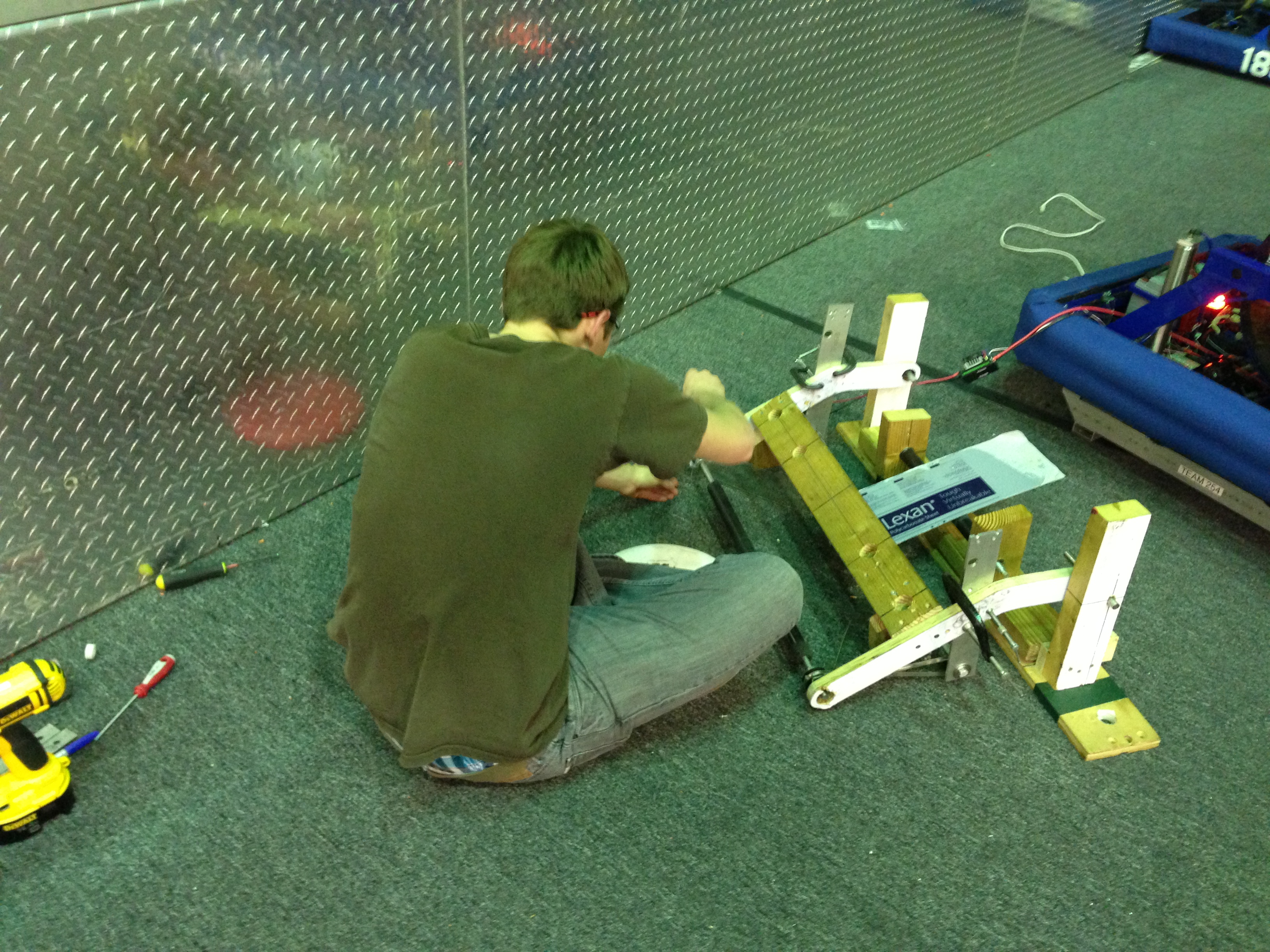
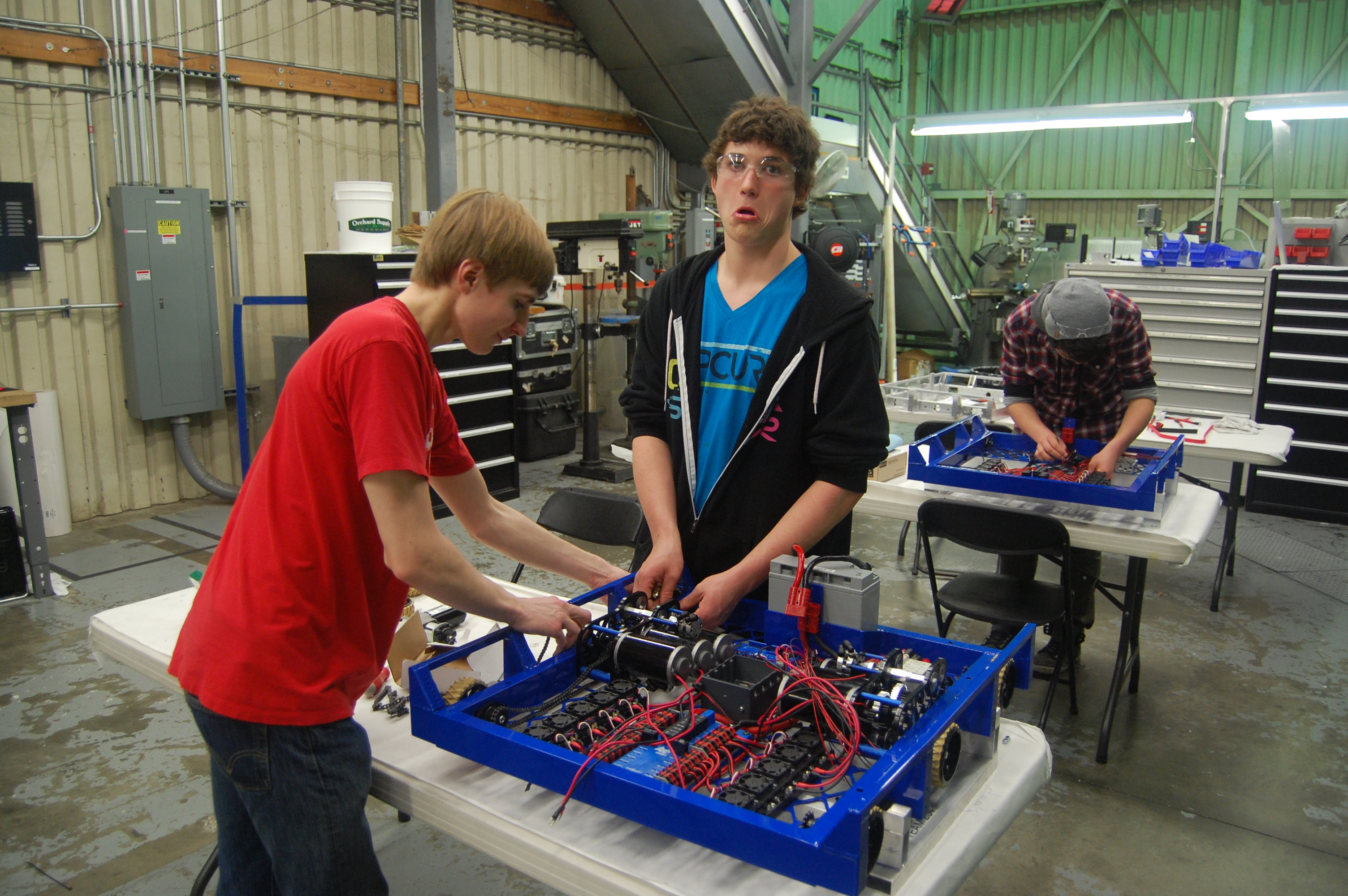
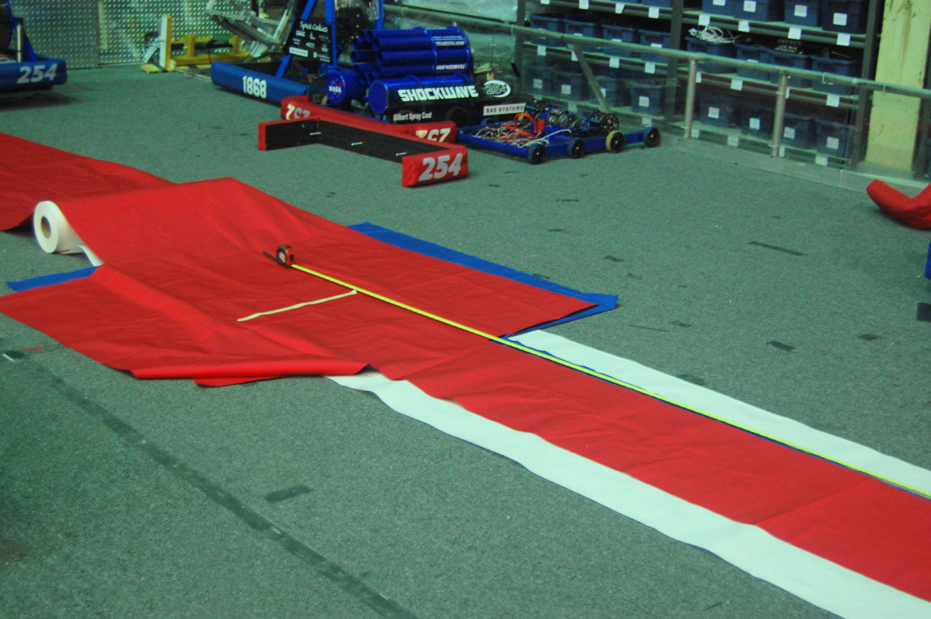
Students continued to make modifications to the shooter prototype. They removed the polycarbonate cover on the top of the shooter and replaced it with an aluminum bar to guide the frisbee through. In testing, the frisbees that are shot seem to consistently go through the high goal. The team expiremented with different shooter positions and angles in the testing, and measured the speed at which the frisbees were fired out. It was found that the frisbee’s velocity upon exiting the shooter was roughly 15 to 20 mph.
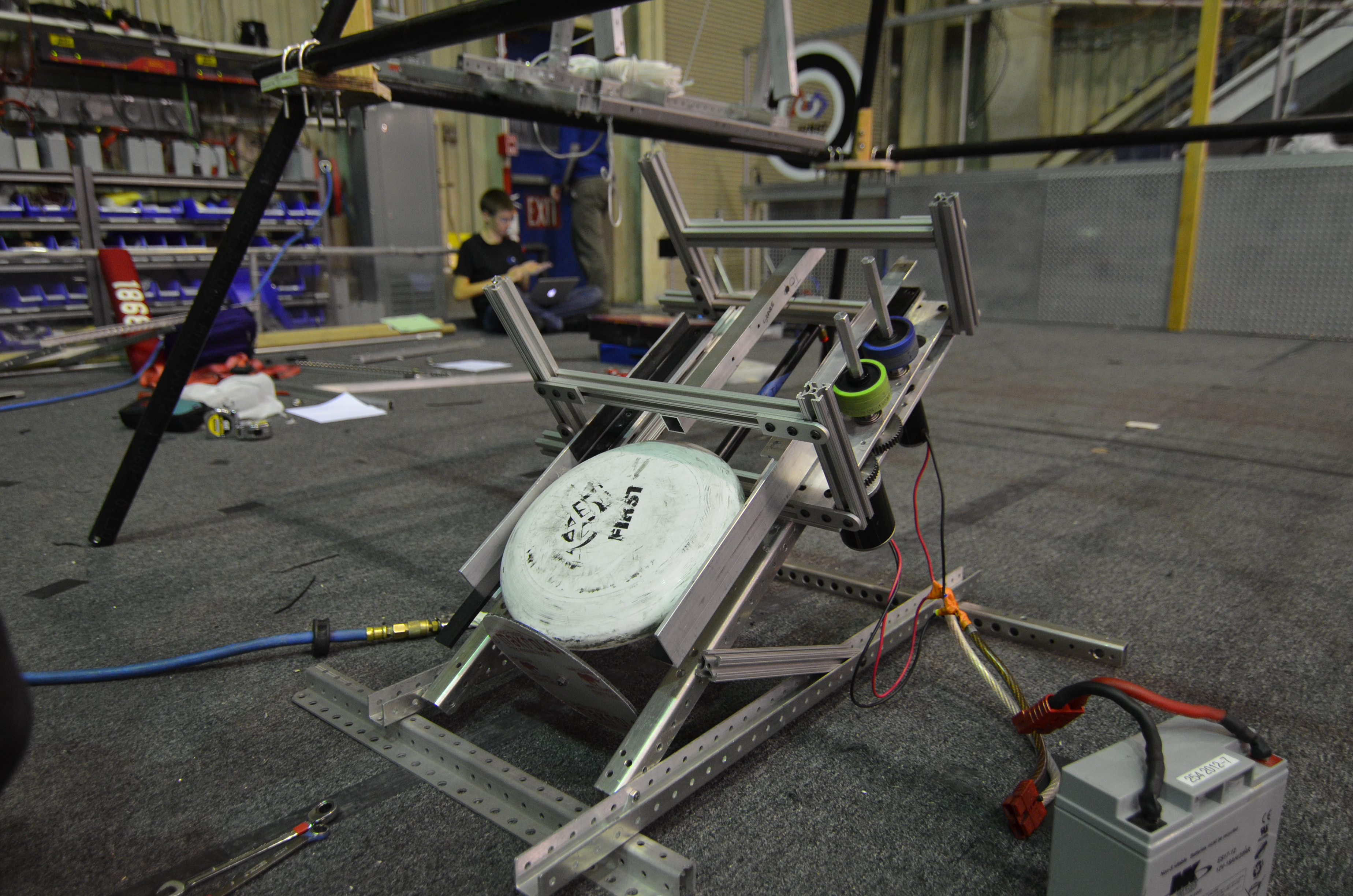
The updated shooter design
Intake
Not much work was done on the shooter today. With the current intake prototype, the frisbee seems to get stuck high on the intake ramp, not touching any vertical rollers. As of now, the intake has been taken apart so that the students can add metal supports (as opposed to wood).
Manufacturing
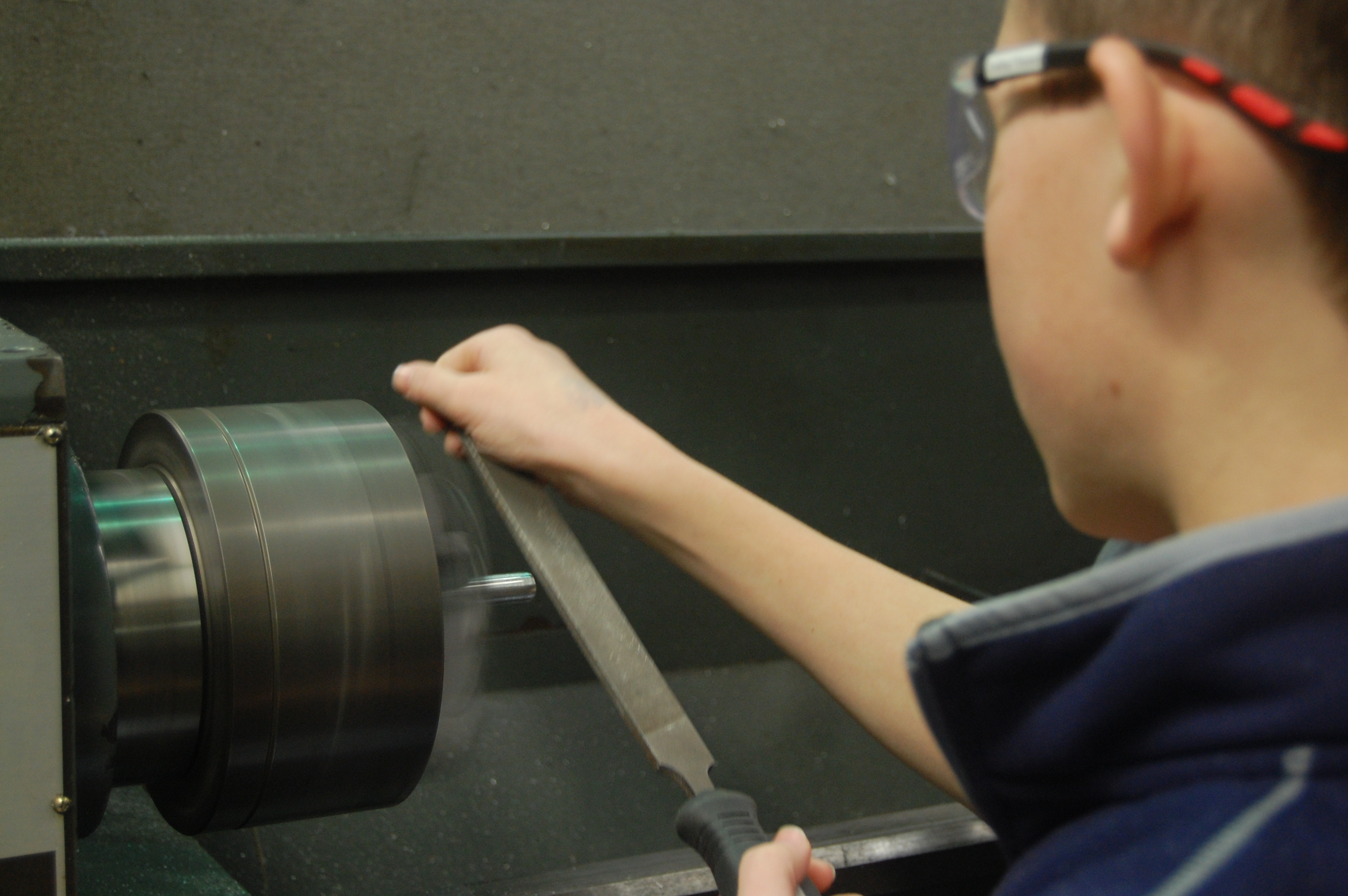
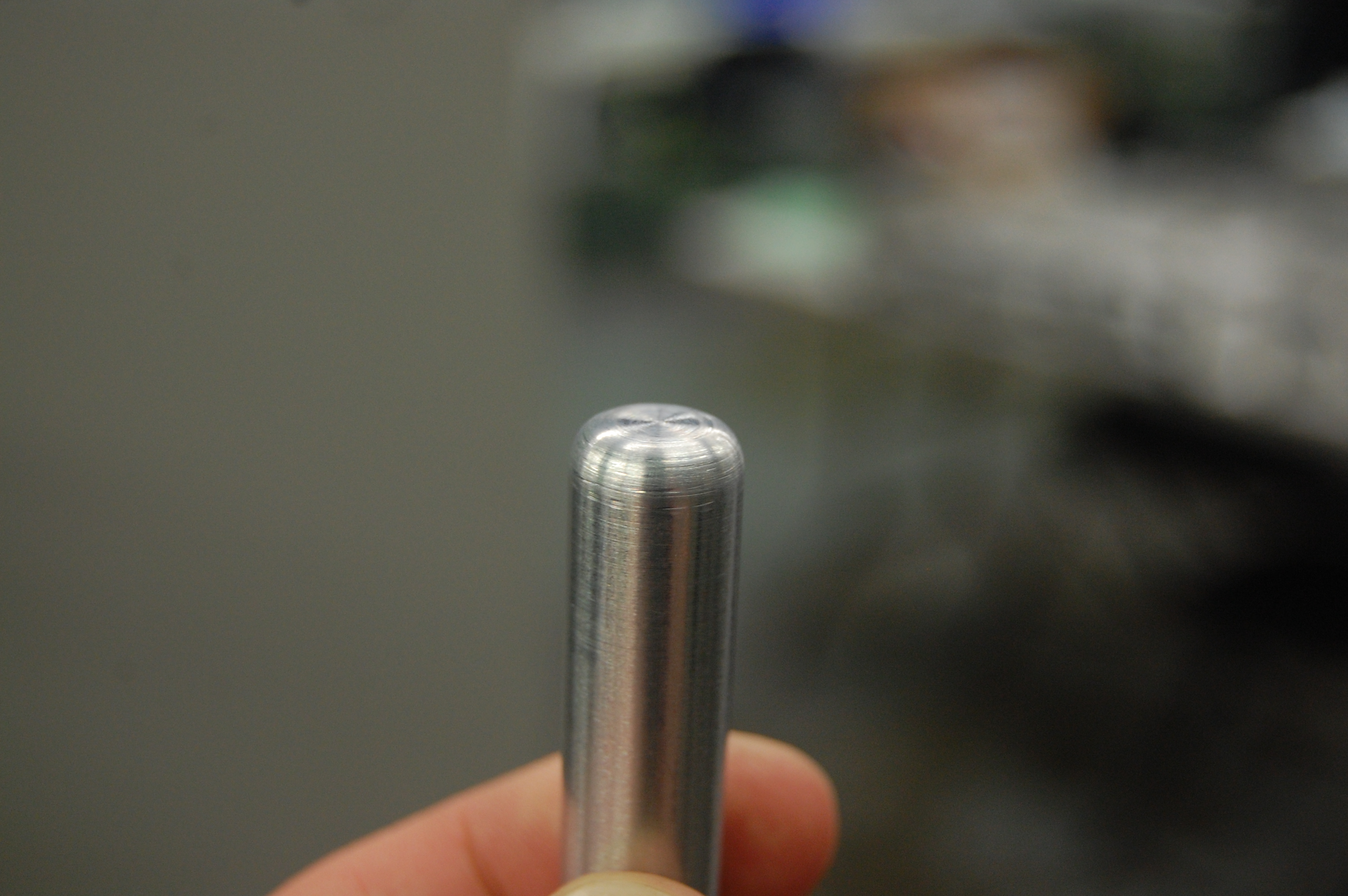
The team continued to manufacture parts for the drive chassis and prototypes.
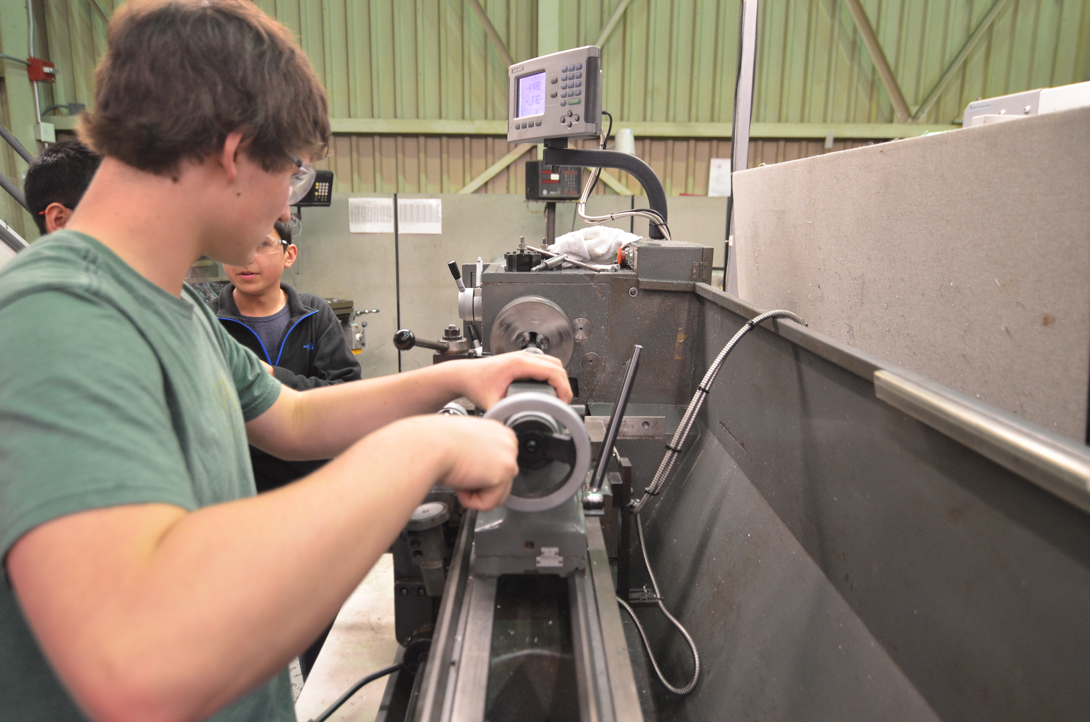
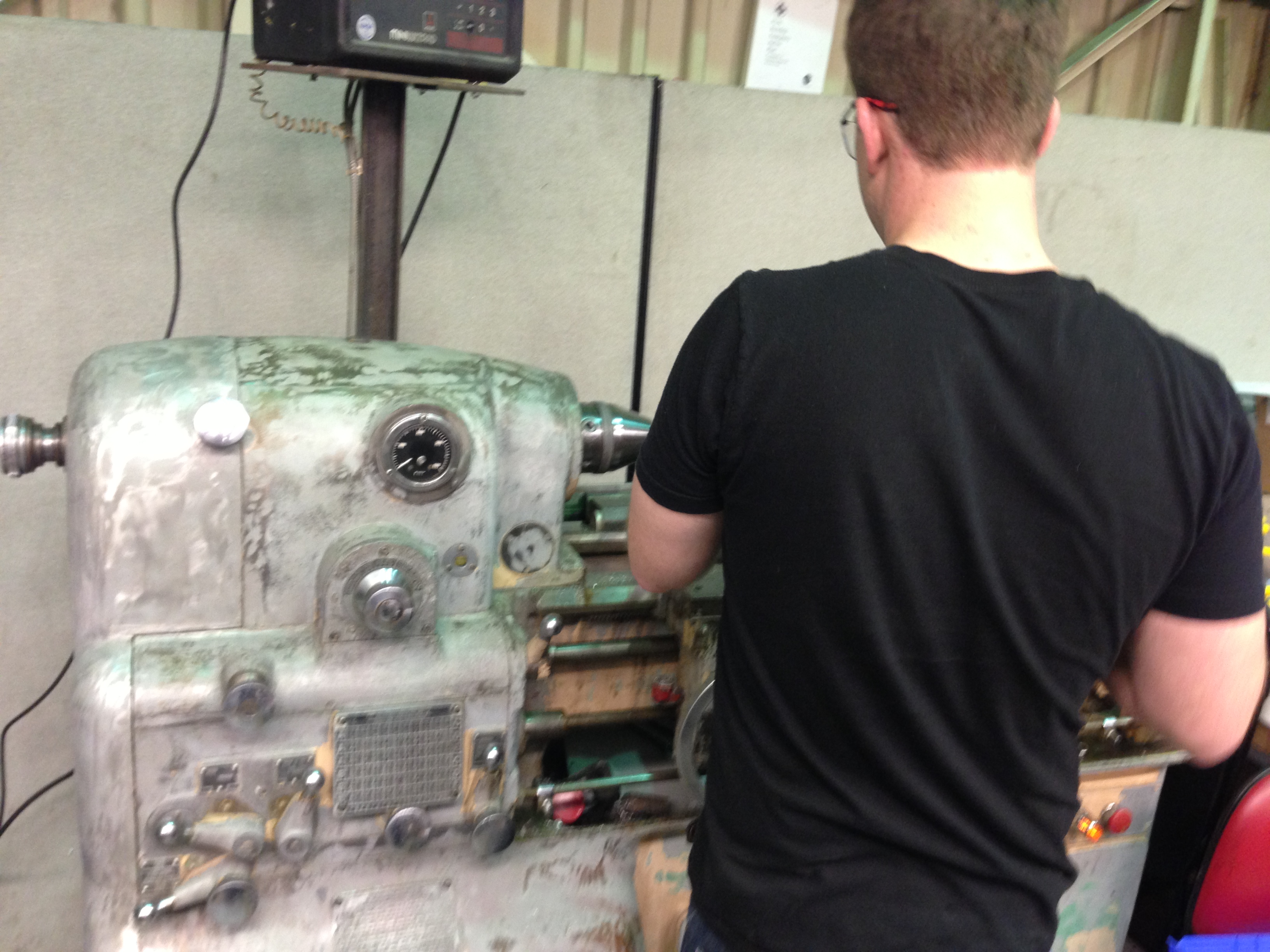
Student making parts on the lathe
Programming
Sensor Testing
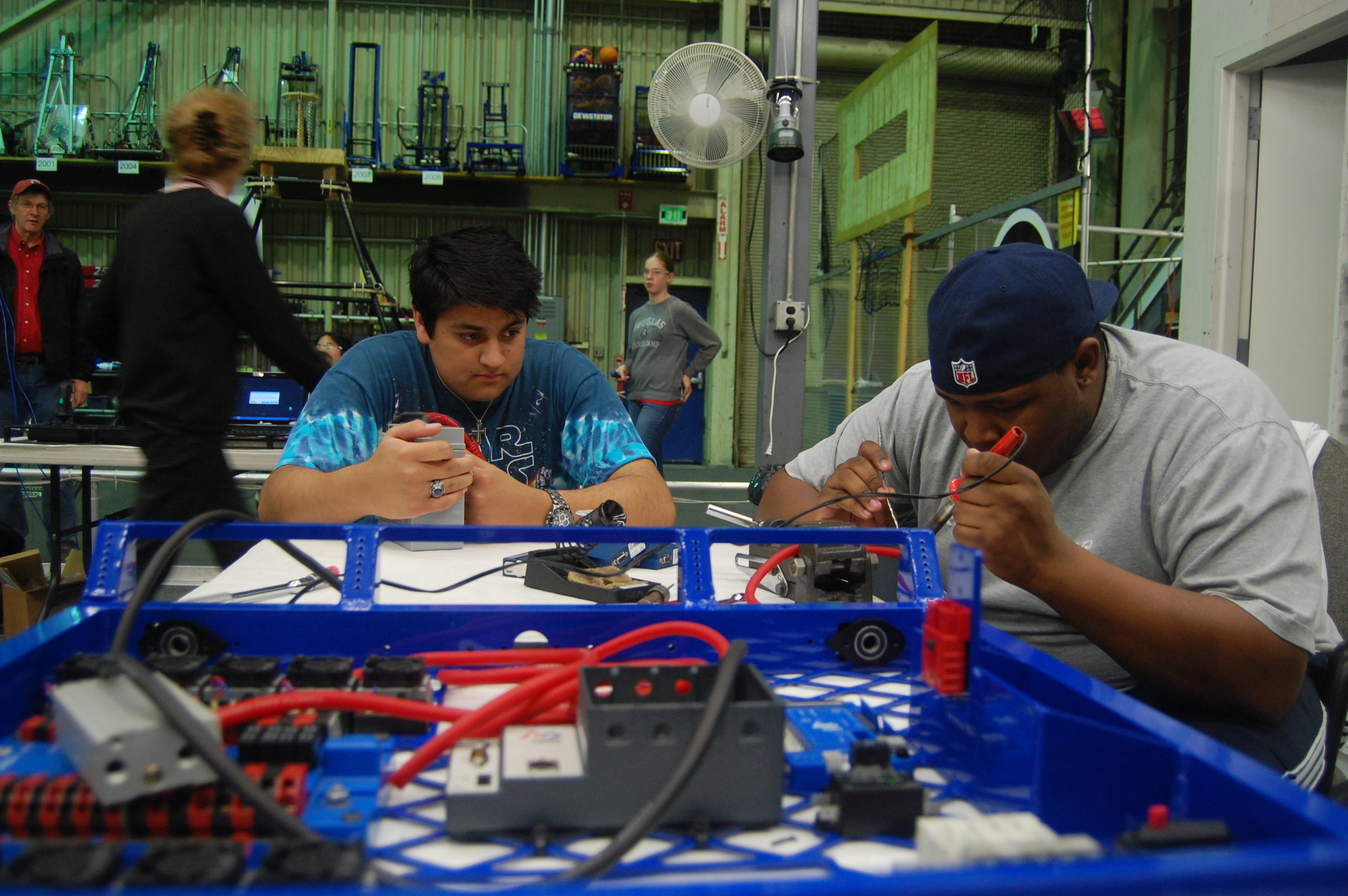
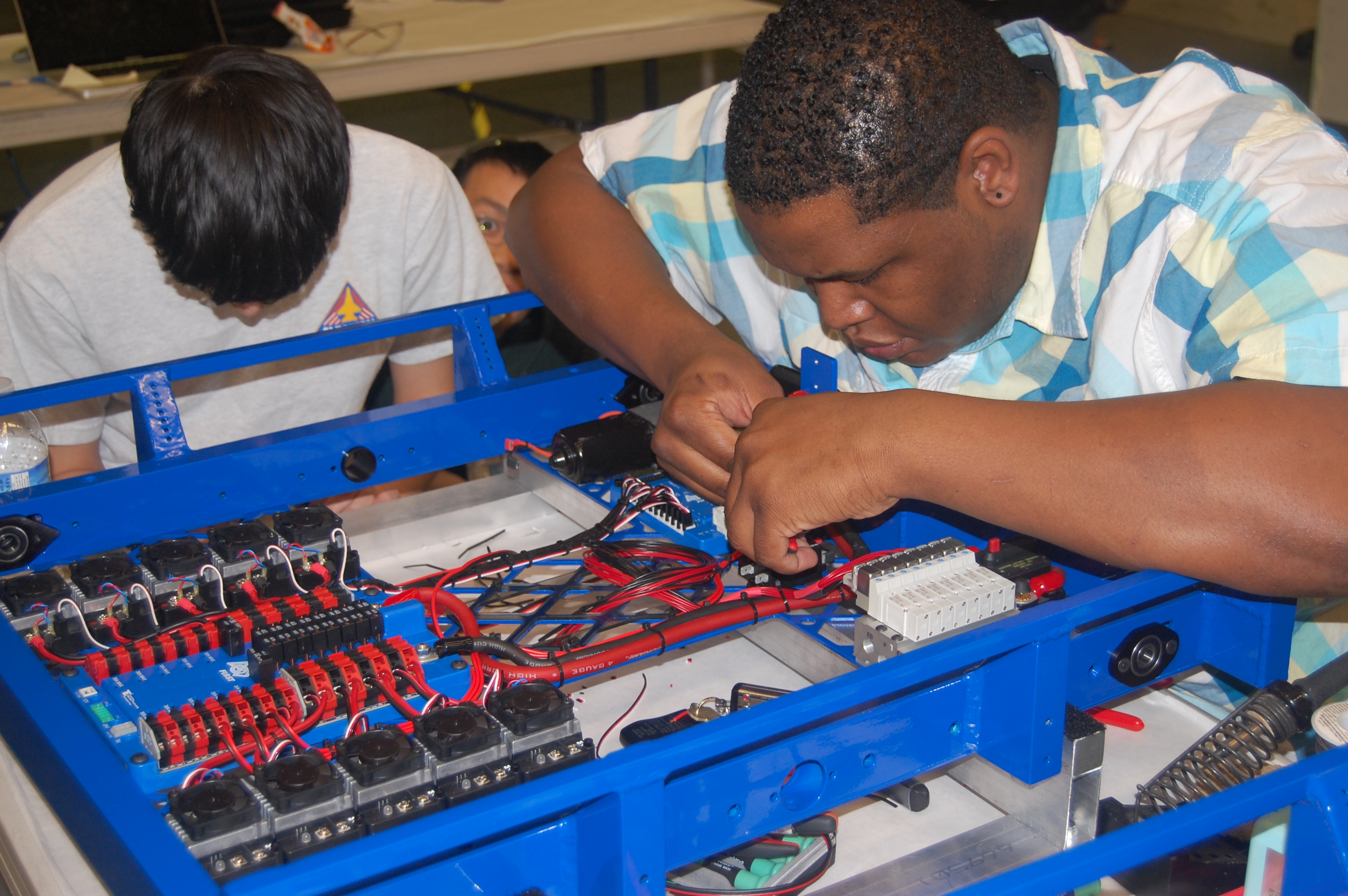
The programmers had a particularly productive day. First, they tested the S4 and S5 encoders. The team realized that the encoders or wiring appeared to be defective yesterday because the encoders kept returning 0. They finally realized that it was indeed a code problem, as they needed to call the start() function on the encoders to start recording clicks. After testing all the S4 and S5 encoders in the 254 electronics bin, all of the encoders were deemed as “functional”, with the exception of one S4 encoder. The broken encoder was promptly labeled as “bad” with the help of some blue duct tape.
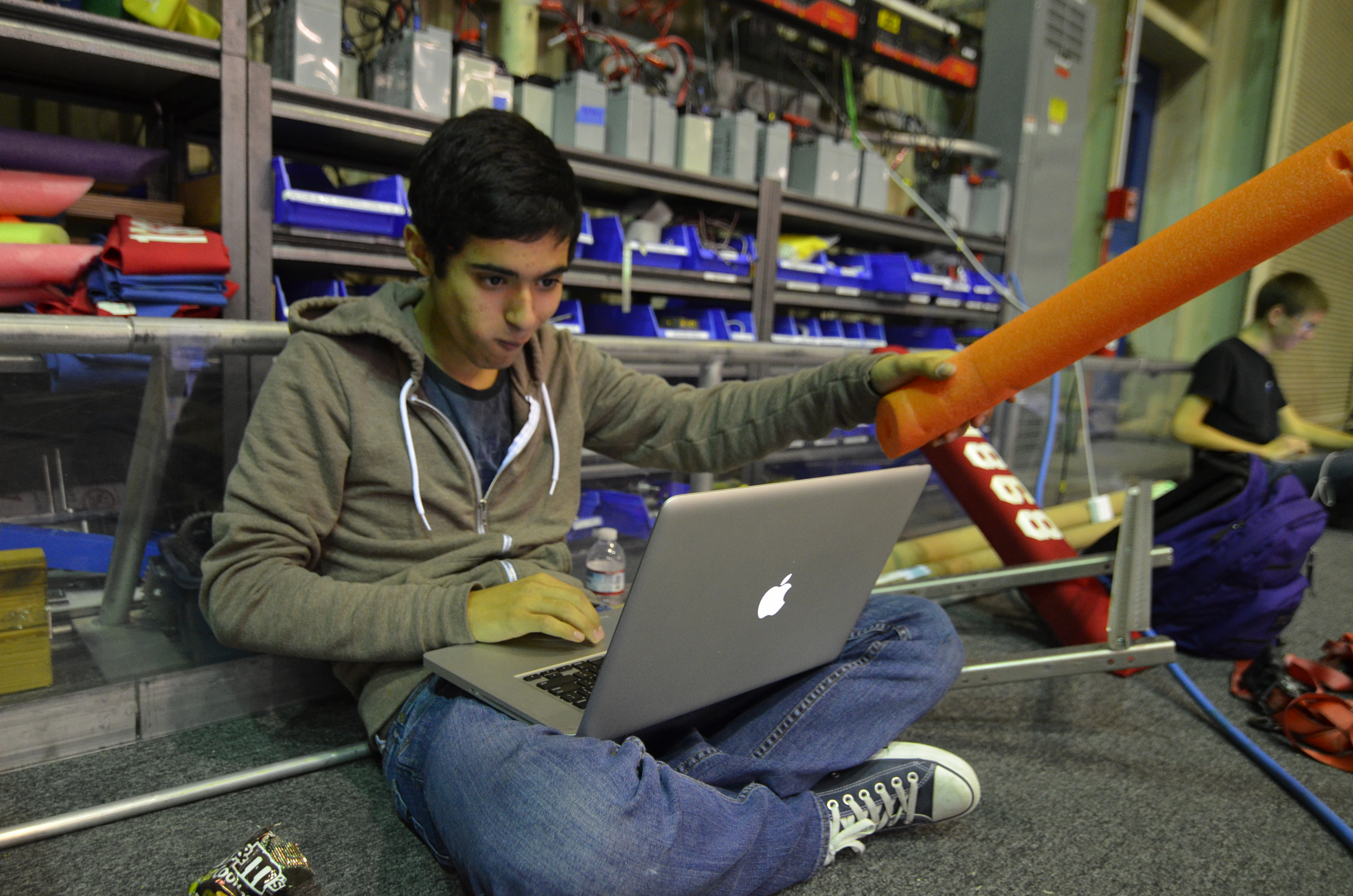
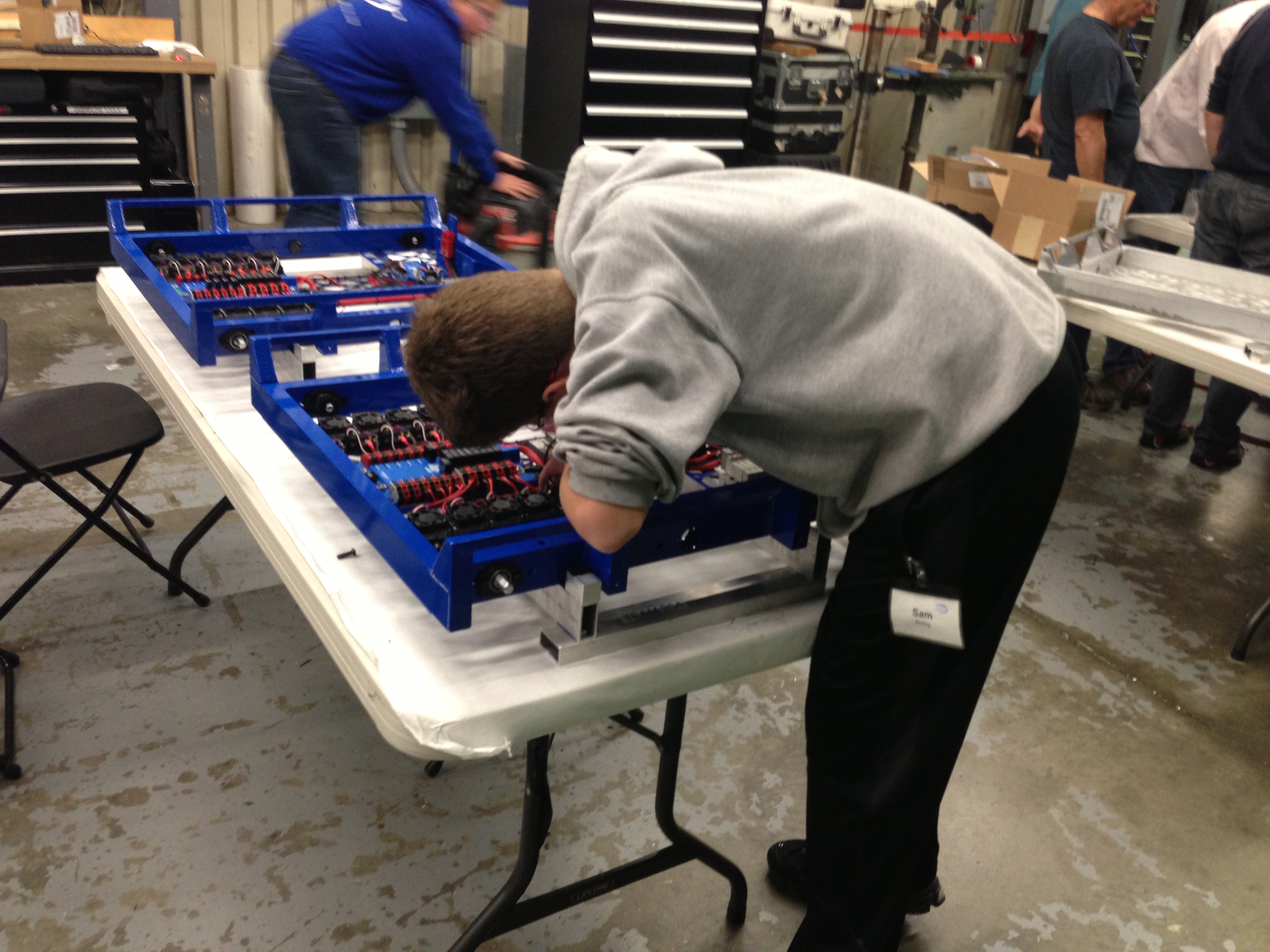
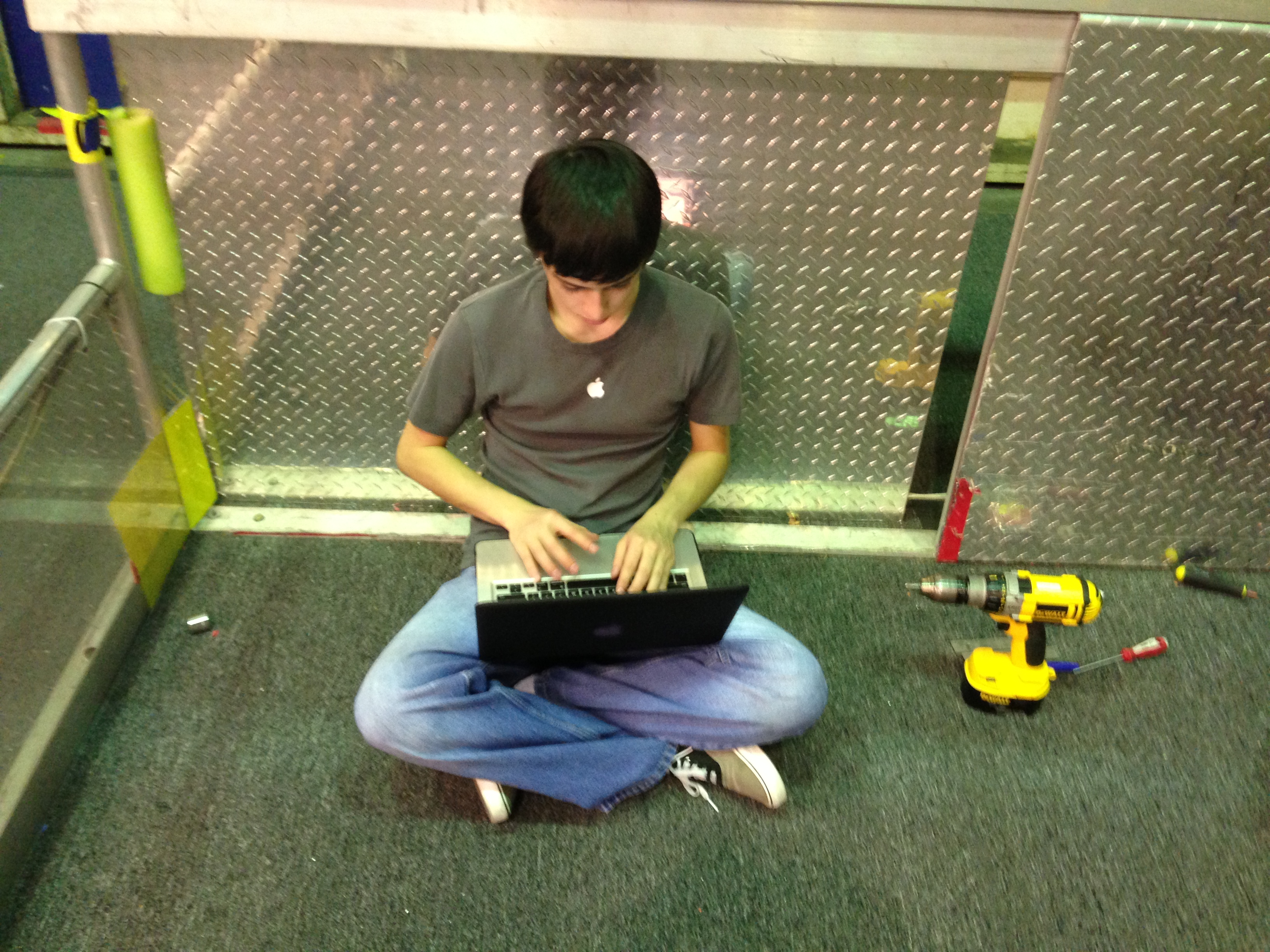
Programming the sensors while wielding pool noodles
Reading Constants
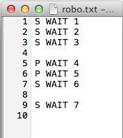
Meanwhile, the programmers tested out a method to read a text file from the robot (Constants.txt) and update the constants accordingly. At first, the team had problems with finding the text file on the robot. Previously, they had been using getResourceAsStream and InputStreams, but switching over to FileConnection and DataInputStream solved the null pointer exceptions. This was a major breakthrough for the programmers. Now, with a Smart Dashboard extension to send text files to the robot via FTP and a way to read and update constants from that text file, the programmers have achieved nirvana.
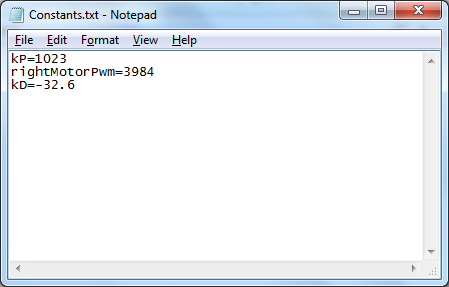
The Constants text file looks like this: a constant’s name = its updated value
CAD
Students began designing the intake mechanism in Solidworks. Though the intake prototype is not yet completed, this step is important because it helps to visually map out the prototype for future assembly.
Action Items
- Continue improving and testing shooter
- Reassemble and work on intake
FRC Day-Off, Week 2
Today was our second day off in the FRC season. We did meet for about an hour today to finish the chassis. The baseplates were picked up this morning from BAE Systems (who watterjetted them for us over the weekend). They were taken to the lab to be assembled with the rest of the chassis. The chassis were jigged up and sent to the welder. Hopefully they will be back in the next two or three days.

One of two chassis getting sent to the welder
Build Season Recipes: Week 2
These award-winning cookies fuelled our continued designing, prototyping and drivetrain-manufacturing activities this past weekend.
Chocolate Chip Cookies
-
1/2 cup butter
-
1/2 cup Crisco
-
1/2 cup sugar
-
1/2 cup brown sugar
-
1 tsp. vanilla extract
-
2 eggs
-
2 1/2 cups flour
-
1 tsp. baking soda
-
1/4 tsp. salt
-
1 handful rolled oats
-
1 cup chocolate chips
Cream shortening and sugar. Add vanilla and eggs; beat. Add flour, baking soda and salt and mix well. Add oats and chocolate chips, stirring slowly. Drop 1" balls onto a cookie sheet and press flat with a fork. Bake at 350°F for 8-10 minutes, until golden brown.
Day #16: Long Range Shooter
Author: Art Kalb
Prototyping
Shooter
After a morning discussion on the mailing list, students and mentors attempted to use the shooter to shoot from a longer range than before. The goal of these long range shots is to pickup discs by the human player and quickly shoot them across the field. In testing, the shooter wheels and guide rail were improved to reduce slippage in the wheels, improving the velocity and range of the shooter. The previous BaneBots wheels were replaced with BaneBots wheels of larger diameter, and more compression was added. By the end of the day, the shooter was able to shoot frisbees through the high goal from the far edge of the field.
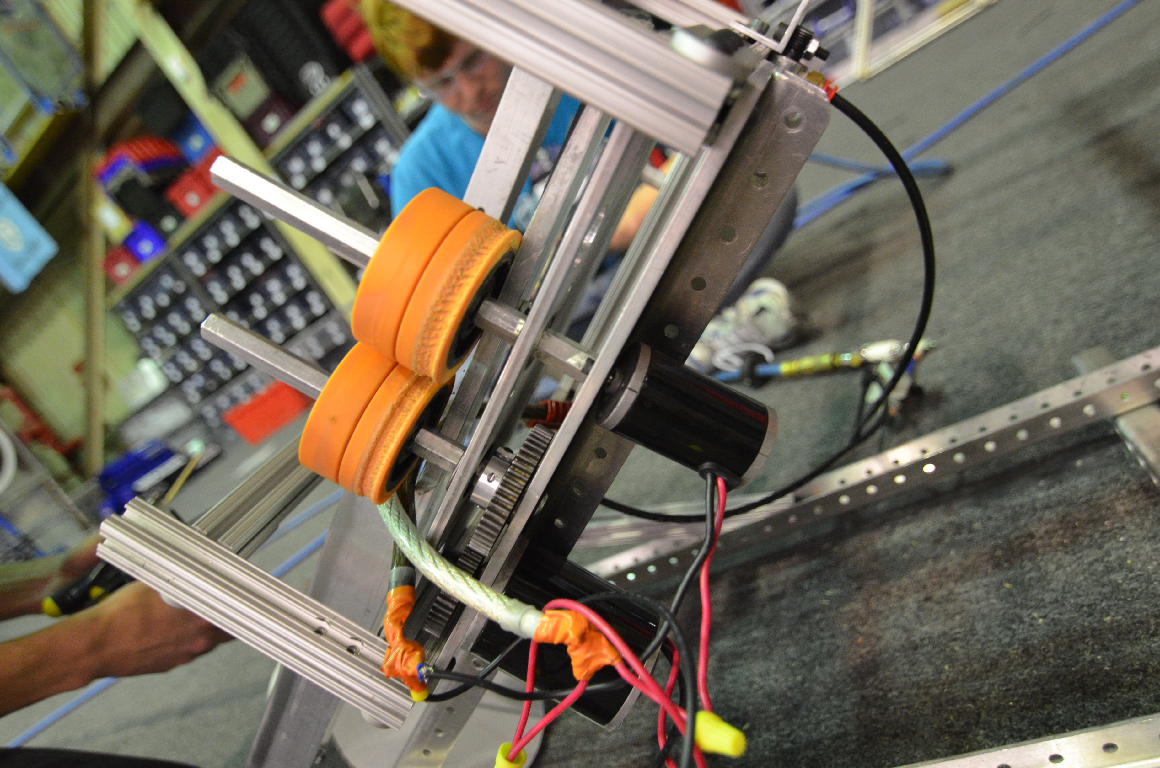
Close-up of updated shooter, with larger BaneBots wheels
Shooting frisbees from far edge of the field
Intake
Students started assembling a new intake, with a roller low to the ground to allow for easy pickup. Currently, this step is high priority, as the team needs a working and reliable intake mechanism for the overall robot design.
Students constructing new intake prototype
Manufacturing
Today, students worked on the lathe for various parts on the drive gearboxes.
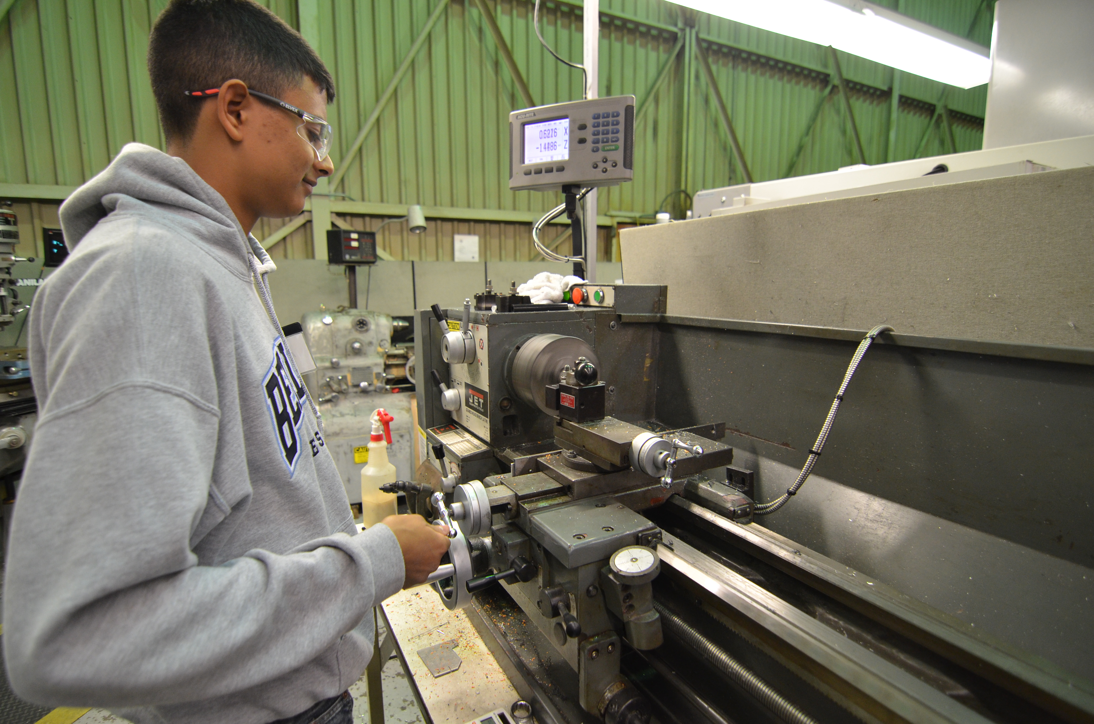
Manufacturing gearbox standoffs on the lathe
Programming
Running the 2010 Robot
Students worked on reviving the 2010 robot’s drivebase to have our drivers (Abhi Kumar and Chris Sides) driving as soon as possible to practice with the Logitech F310 controller. Tasks involved modifications to the CheesyDrive code from 2012 and mapping the gamepad axes to the drivetrain, and reimaging the cRIO to v47.
The 2010 robot, Onslaught
Matrix Math
As a part of the program, the robot will need to do some mathematics involving matrices. To allow for this, students translated and reimplemented code to create a Matrix class, which will do basic matrix math (addition, subtraction, scalar multiplication) and matrix mulitiplication. Due to some uncertaintity about matrix multiplication, the class is not completed.
The students also worked on translating the state space controller from last year’s C++ code, which requires a functional Matrix class.
Action Items
- Finish and test intake prototype
- Improve shooter for speed, distance, and accuracy
- Finish translating matrix/control code from 2012 to Java + test code
- Flash v47 image to Skyfire
Day #17: Chassis Arrives & Prototyping Continues
Prototyping
Intake
Students began building a new prototype intake. With four small, vertical, rollers and one large horizontal roller, the intake should work well once complete.
Working on the latest intake prototype
2010 Robot
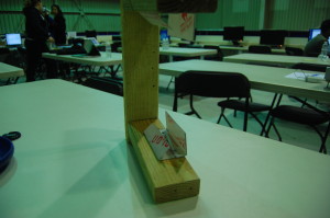
Students continued constructing a simple bumper onto the 2010 robot, Onslaught. Once complete, the new prototype intake will be attached to the bumper and tested for performance. Also, once the 2010 robot is operational, our driveteam can begin practicing. Currently, the left side bumper is placed on completely, but the wooden block on the right side is too short. Students will fix the right side bumper as soon as possible tomorrow.
Attaching wooden “bumpers” onto the 2010 robot
Manufacturing
Today, the team recieved the drivebase chassis back from S&S Welding after sending them out on Monday. Students brushed the drivebase chassis in order to get them ready to be power coated. They will be sent to Pacific Coast to be powder coated tomorrow. The team expects to get them back by Friday.
Scotch-briting the drivebase chassis
Students also used the lathe to machine spacers for gearboxes. These should be finished tonight or tomorrow morning. Once the plates and shafts are complete, the team will begin to assemble them.
Programming
The programmers continued to work on translating state space and matrix code from 2012’s C++ code to Java. Currently, they are trying to implement a function that multiplies two matrices together.
Meanwhile, the latest cRIO image (v47) was successfully flashed to the 2012 robot today. However, the students need to re-deploy the code onto the robot, as the code was erased in the process of re-imaging.
Action Items
- Continue machining the shafts and plates for the gearboxes
- Continue testing the 2010 robot and let drivers practice
- Continue designing the shooter, climbing mechanism, and intake
Day #18: Powder-Coated Parts
Prototyping
Intake & 2010 Robot
Students continued to develop an intake prototype, now attached to Onslaught, and the intake will be completed as soon as possible. However, due to the arrival of the chassis, students removed Talons from Onslaught to be placed on the new drive chassis. This transfer means that we do not know which robot (Onslaught or Skyfire) that the drivers will practice on, but Onslaught will still be used for testing sensors.
Manufacturing
Today, GIlbert Spray Coat returned the powdercoated chassis a day earlier than expected, and students began working on putting electronics onto the frame, such as the power distribution board, ten Talons each, digital sidecar, the Spike relay, the power switch, and solenoid. Additionally, Pacific Coast Metals returned other anodized parts, such as gearbox plates and spacers.
If the shafts are returned from Modern Machine Company tommorrow, work on assembling the gearboxes will begin. However, there are a few missing parts that still need to be aquired. The 40T gears, shifting dogs, shifter shafts, and a few other parts from West Coast Products are still missing.
The bearing housings were received from Pacific Coast. Mentors and students worked on pushing the bearings into these housings
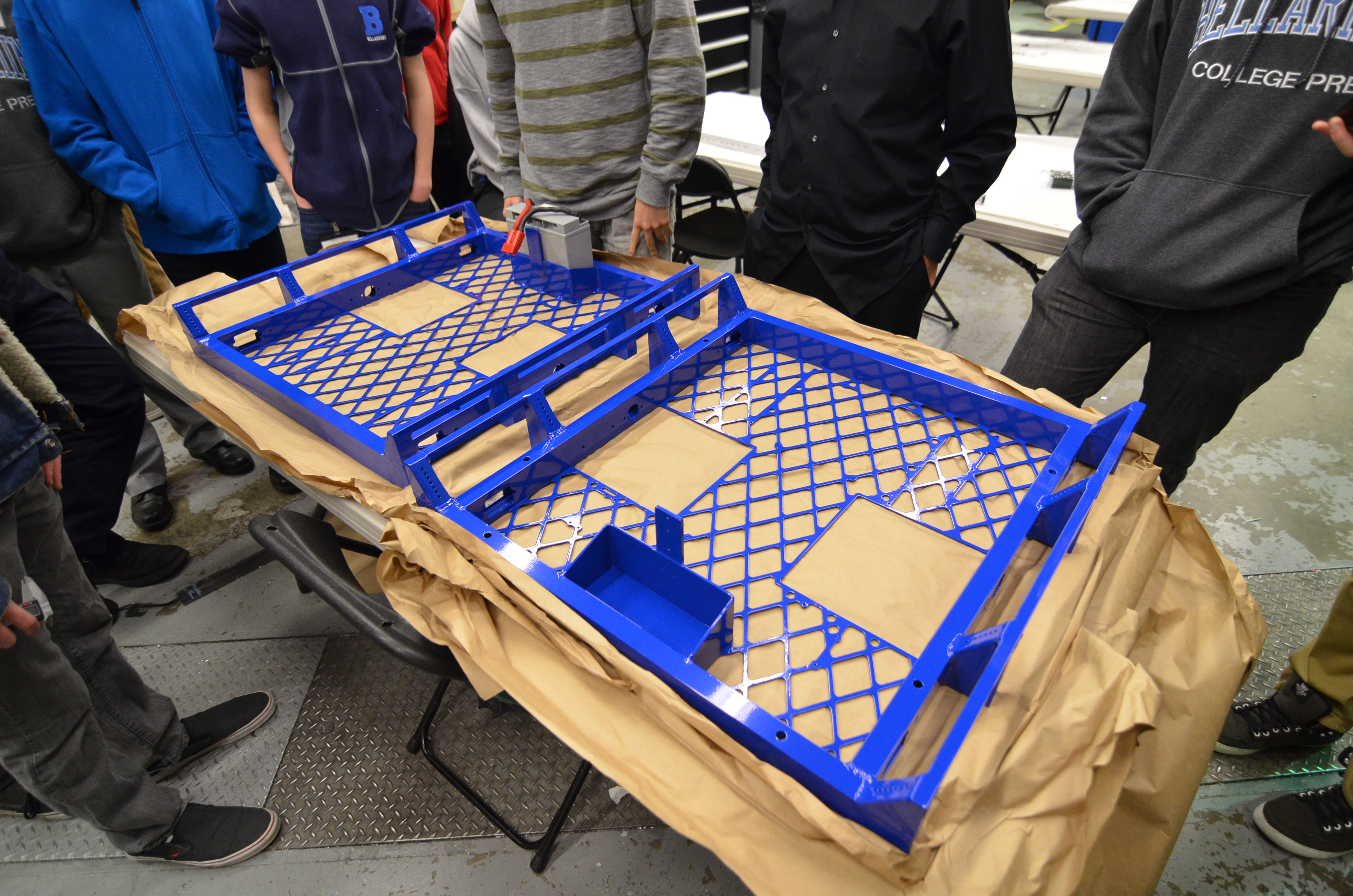
The two powdercoated chassis
Programming
Today, the students spent most of the time trying to make a VEX ultrasonic sensor work on an FRC robot, in order to determine the orientation of a Frisbee. Most of the time was spent debugging the sensor, as the sensor was returning arbitrary and random values. The programmers discovered that the two port numbers should be switched in the code, which made the ultrasonic sensor work. However, during testing, the sensor seemed to be able to detect surfaces a maximum distance of around 3 inches away. This is a problem, as the VEX ultrasonic sensors are designed to be able to detect distances of up to 115 inches away. The team thinks that interference from the surroundings could possibly affect the sensor’s abilities, but more tests and debugging will be done tomorrow to get to the root of the problem.
In addition, a couple of the robotics laptops were transfered to the lab for programming use; however, the nature of the Bellarmine servers prevented work from being done on the laptop. Currently, the team needs to reinstall the wireless card driver on the laptop.
Action Items
- Debug and test ultrasonic sensor
- Continue working on the intake
- Continue adding electronics to the chassis
- Continue designing the shooter, climbing mechanism, and intake
- Start wiring
Day #19: Reconstructed Intake
Prototyping
Intake
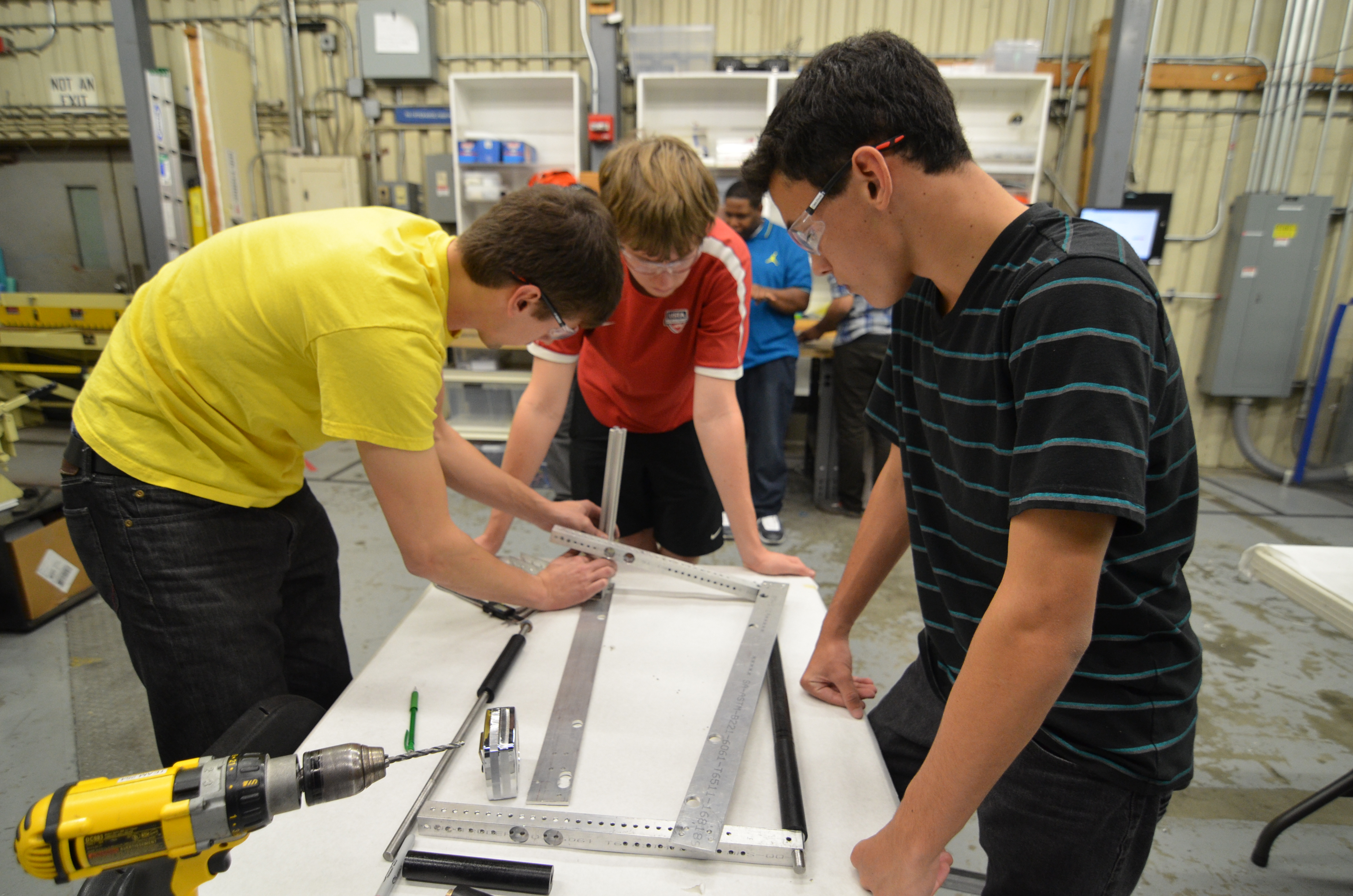
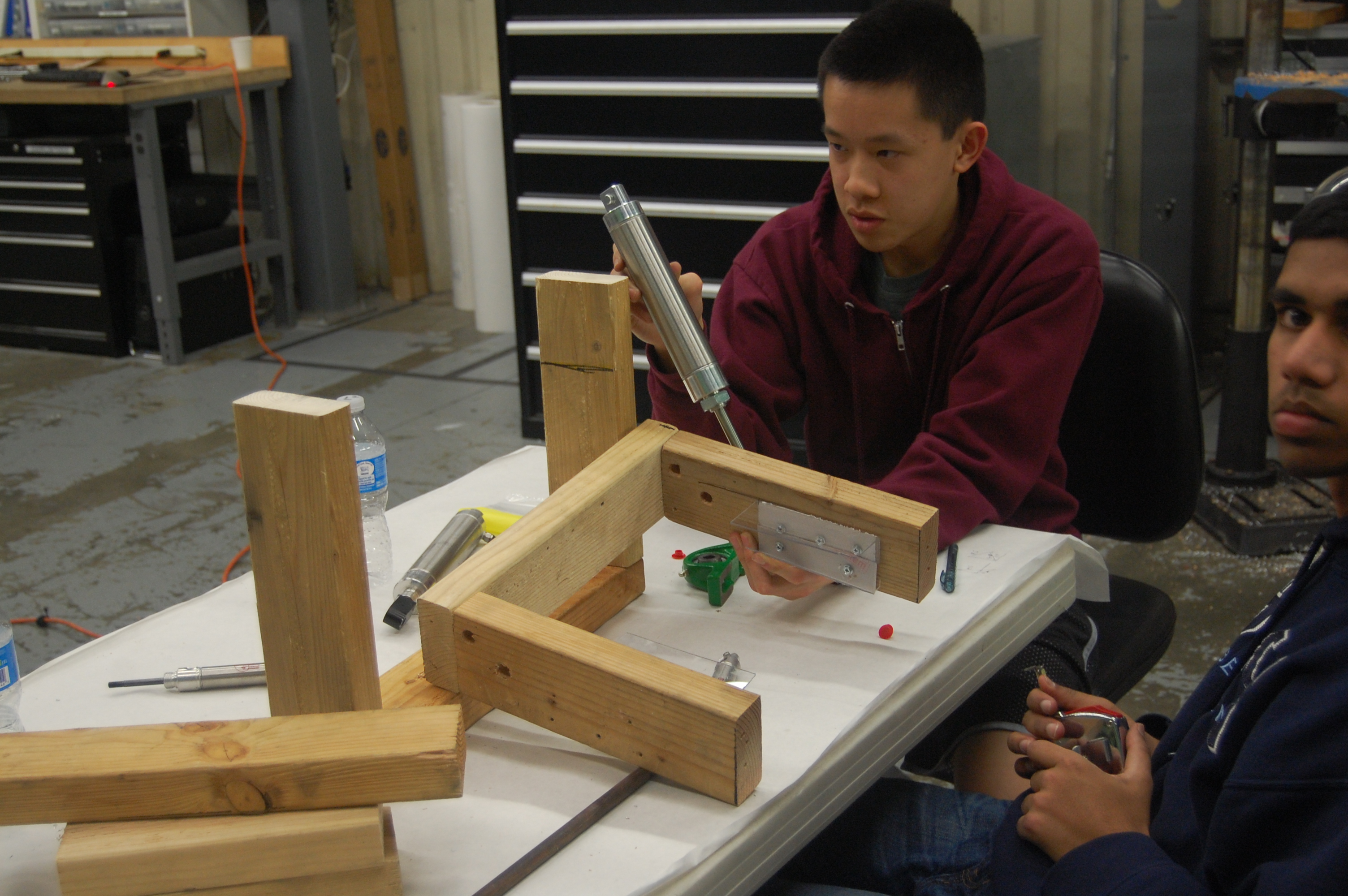
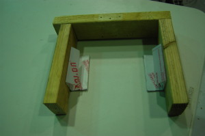
Students continued to make modifications to the intake prototype. They scrapped the entire aluminum model because they decided it would be too time inefficient to drill and redrill holes into metal. Instead, the team constructed the front of the robot frame and the intake prototype with wood. A life-size drawing of the intake arms was printed out and glued onto a wooden block. Then, the intake arms were cut out with the vertical bandsaw along the traces.
In addition, shafts were manufactured on the lathe for the intake prototype. The team plans to have the intake mechanism fully designed and tested by Saturday, or Sunday at the latest.
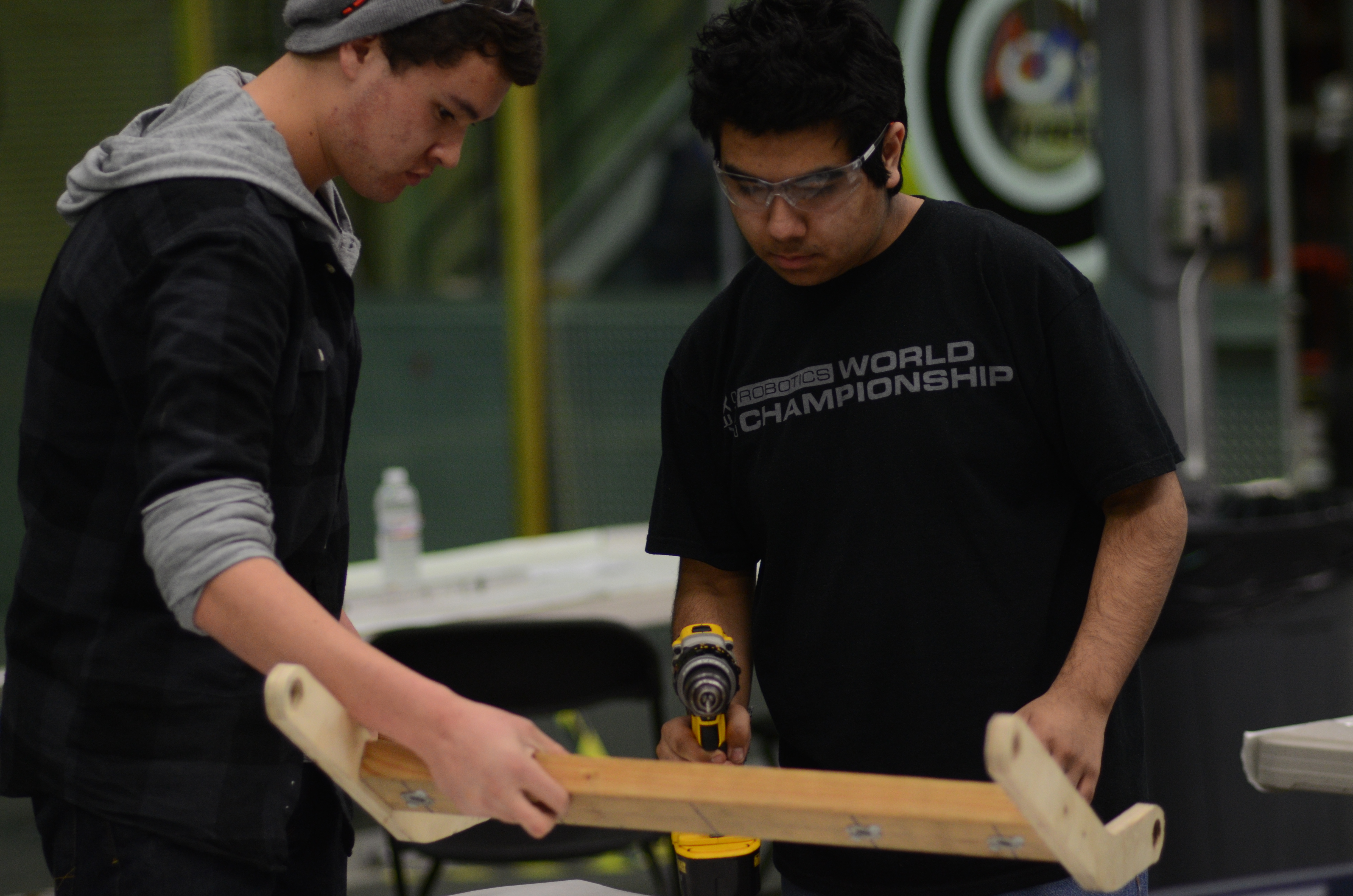
Students assembling an intake prototype with wood
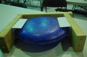
At around midnight last night, the team decided to remove the vertical rollers and add a bottom roller. This resulted in a much simpler two roller design which worked really well. The front roller is still 25″ long, while the back roller is 12″ long. Students also added passive polycarbonate funnels on each side so that the frisbee is in the center by the time it hits the roller.
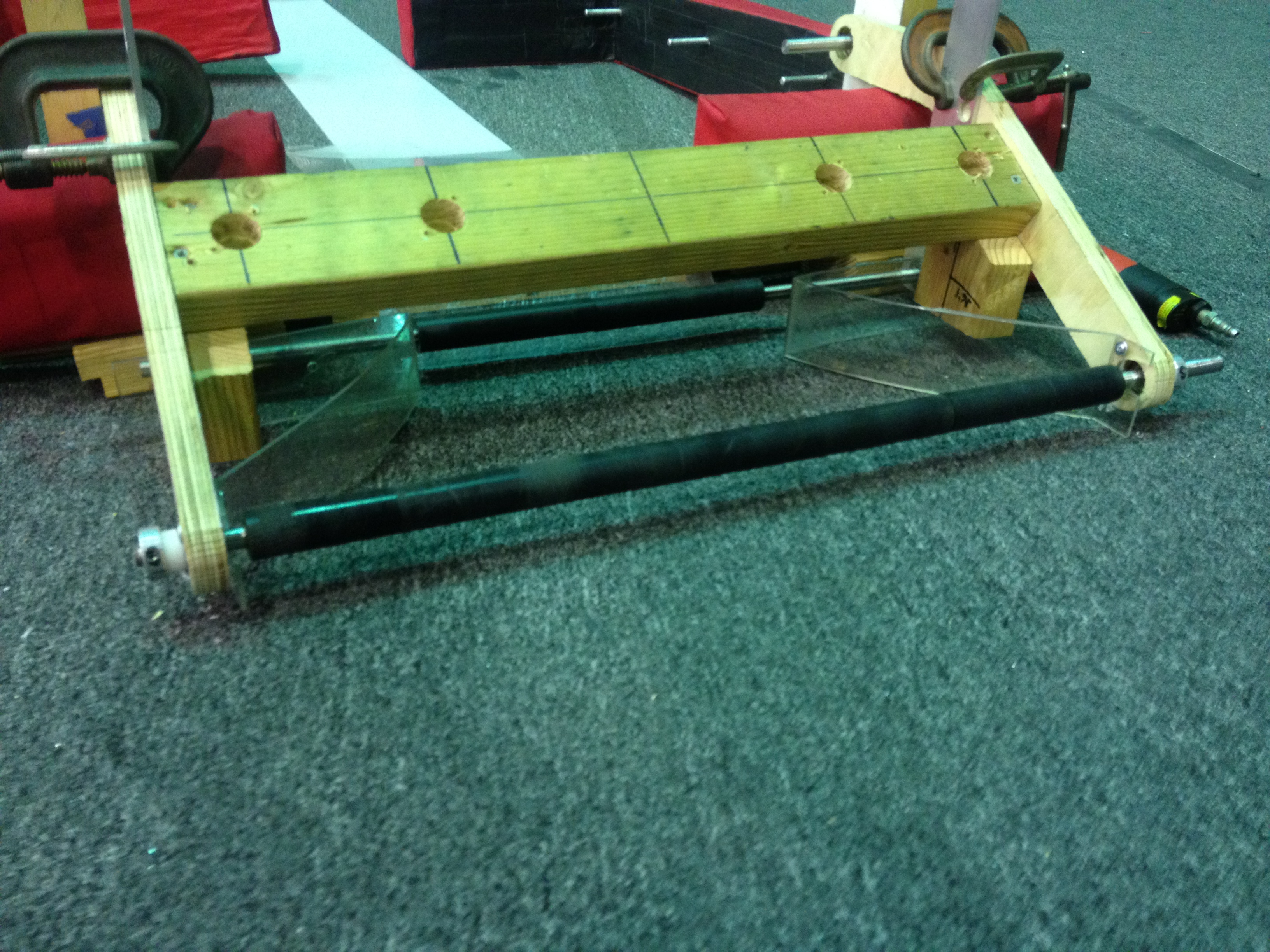
Intake with bottom horizontal roller
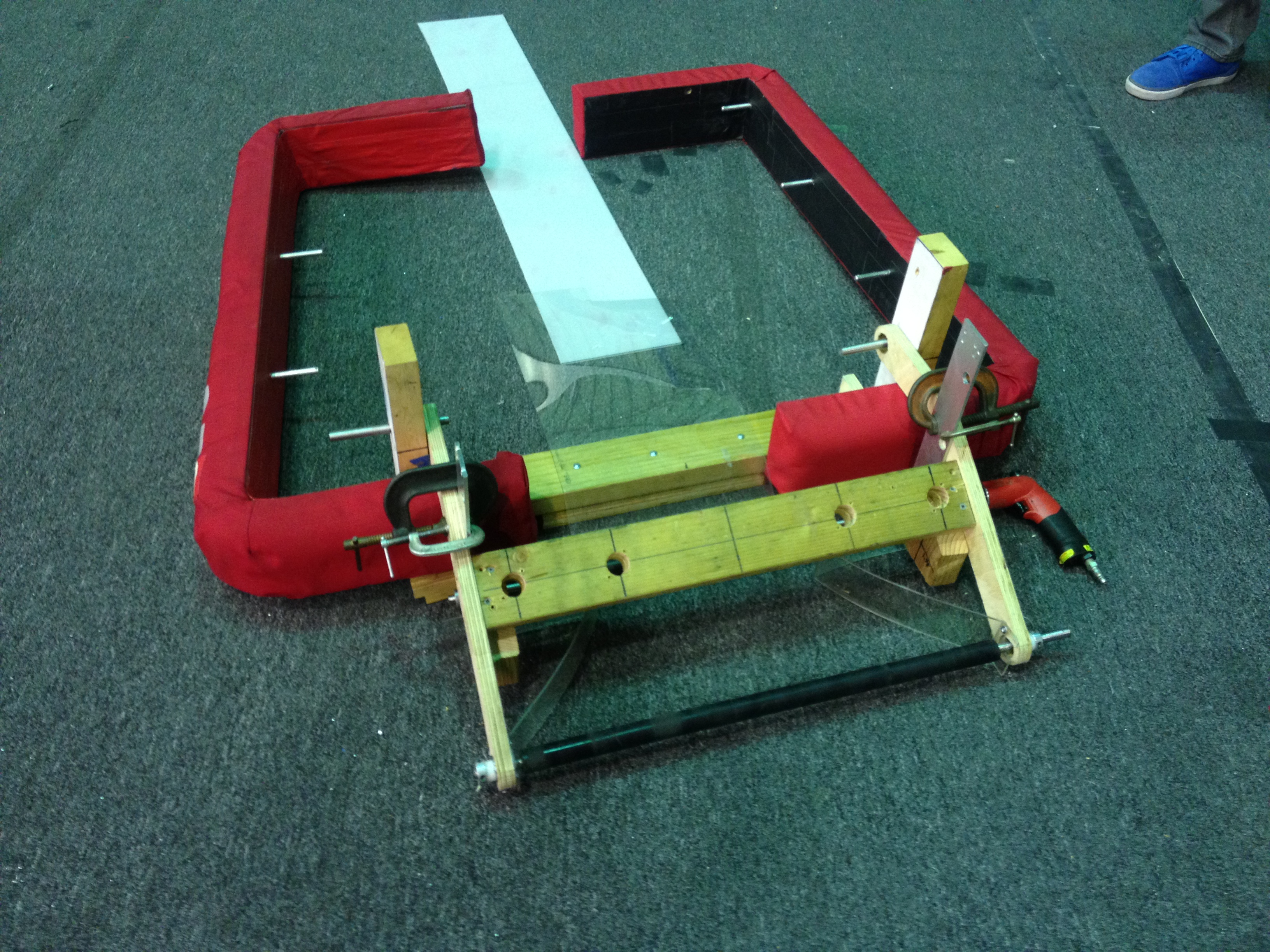
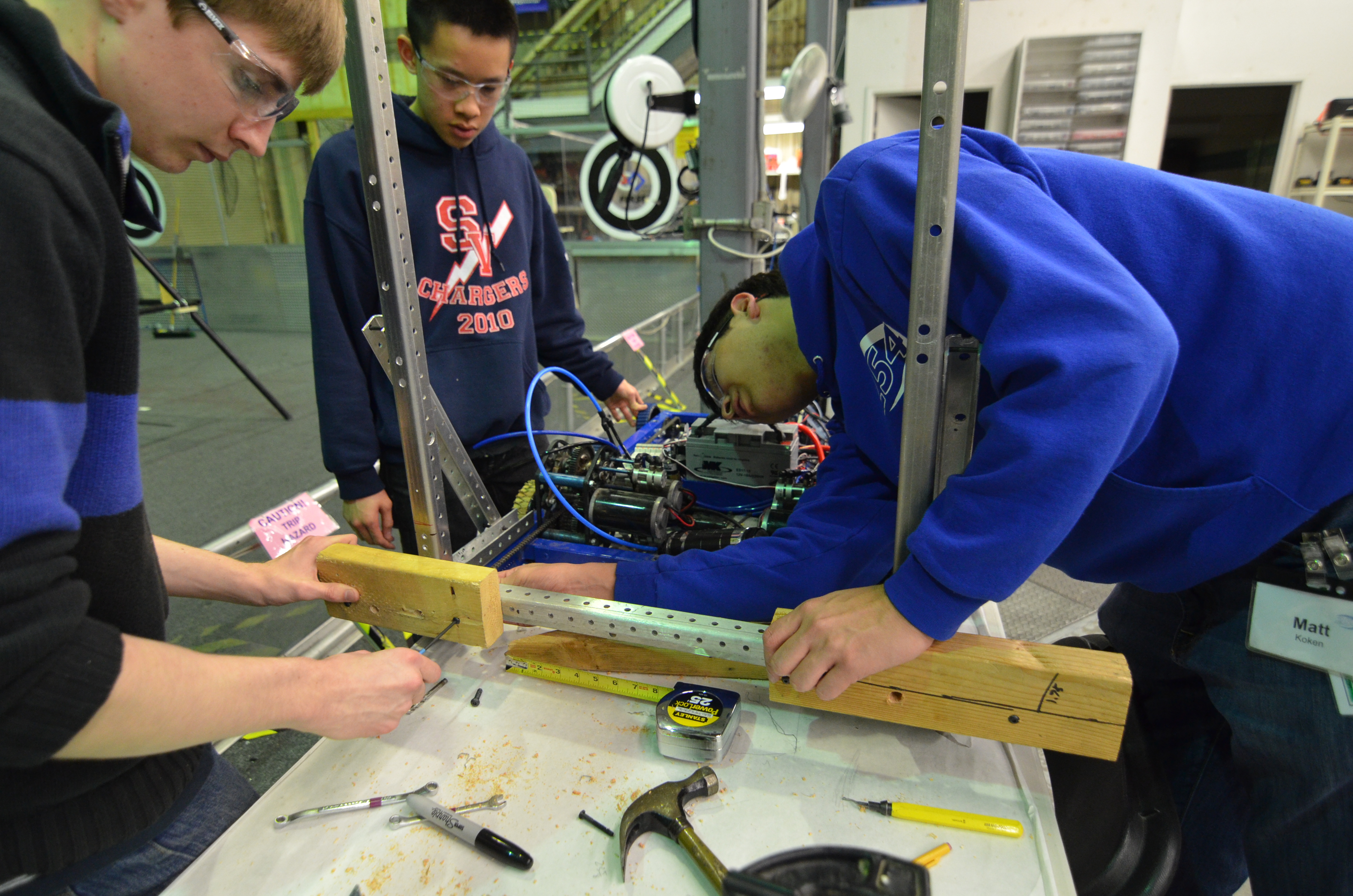
Intake attached to wooden bumper frame
Meanwhile, students also created a wooden bumper frame out of wood to mount the intake mechanism. Like the new wooden intake, a wooden frame would allow the team to more easily drill and make modifications to the prototype.
Creating wooden bumper frame
Programming
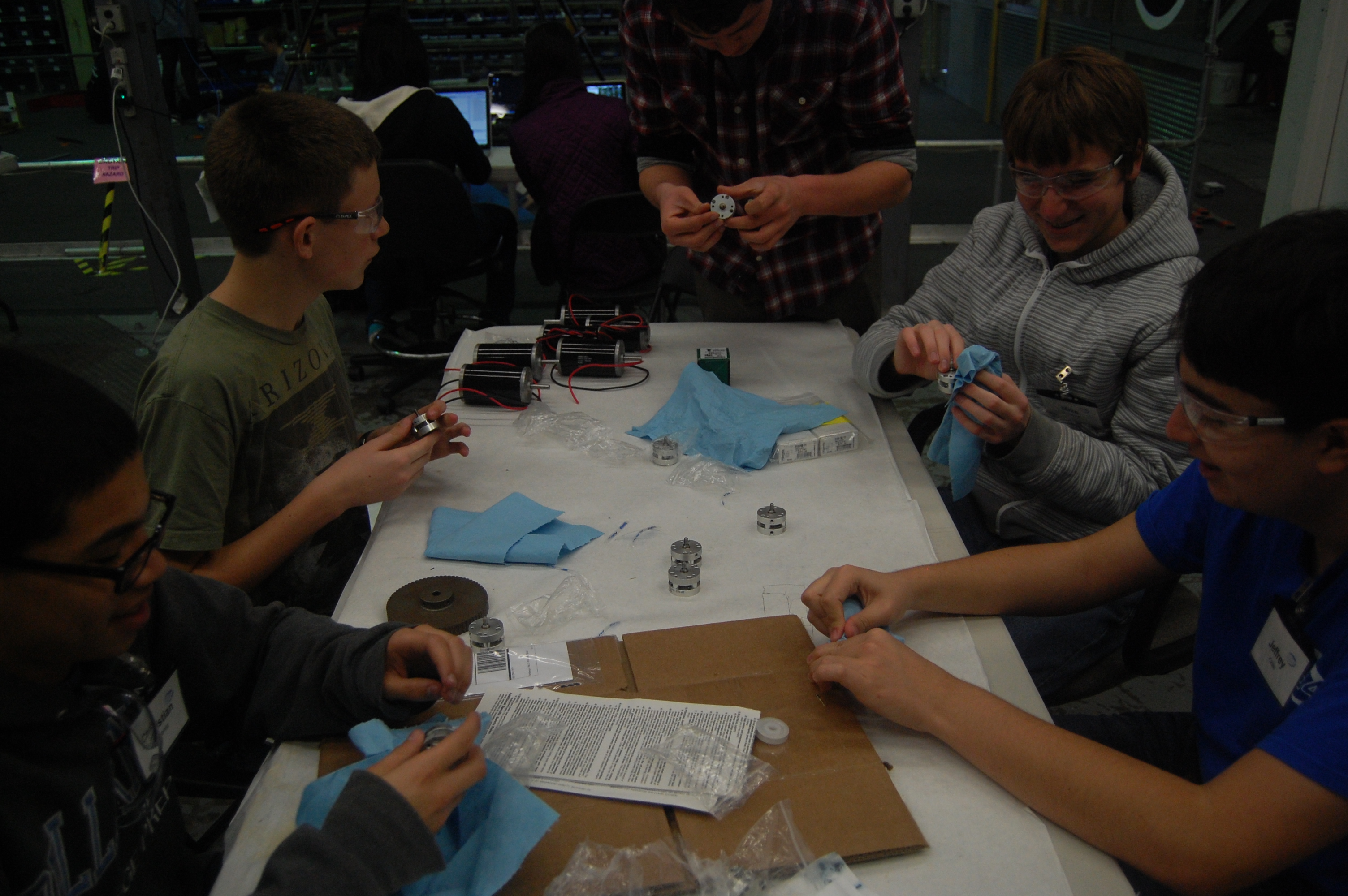
Sensor Testing
The programmers had a very successful day. They began by bringing in and testing two additional VEX ultrasonic sensors from the VEX lab. Upon testing, the students found that one of the additional sensors was significantly better than the previous single ultrasonic sensor. The better sensor can detect surfaces of a distance greater than 12 inches, whereas the old sensor could only detect up to 3 inches. Though the VEX ultrasonic sensor works when tested with the shooter prototype, the team is still exploring other sensors as ways of detecting the orientation of the frisbee.
Testing the three VEX ultrasonic sensors
Control
The programming team traveled upstairs for a group programming session, using one single laptop and a projector. The students worked together to implement a Controller class and reimplement WPILib’s PIDController. Instead of having multiple threads for each of the controllers, the team created a way to update each controller in one thread. This was done by making the Controller class and abstract class that held onto a static Vector of Controller objects. Then, in the constructor of the Controller class, “this” controller would be added to the Vector. Finally, a method called updateAll() would iterate through the Vector to update all of the controllers. This was a breakthrough moment for the programmers, as a solution utilizing fewer threads would make the whole process more light-weight.
When this new code was deployed to the 2012 robot Skyfire, no exceptions were thrown and no errors seemed to pop up. Miraculously, the code worked flawlessly on the first try!
Action Items
- Continue assembling intake prototype
- Reimplement and commit state space controller class
- Add conveyor to intake prototype for the purpose of constraining the frisbee in all directions.
- Prevent frisbees from getting stacked once they were through the intake
- Turn down front roller to 3/8″ so that it can be driven with the pneumatic drill
- Model new intake in Solidworks
Lab closing time for the night was 2:30 AM
Day #20: Funneling Intake and Wiring
Intake
Today, many students worked on the funneling intake. We tested many angles, and elevations, to account for the robot in motion. This funneling intake works through 3 steps. First, the frisbee is sucked in to the intake assembly by a roller that spins over/on top of the frisbee. From there, the frisbee is funnelled by two plastic angled “walls” into a smaller chute. From here, a last conveyor moves the frisbee into the conveyor. Today the students worked on varying the distances the rollers were offset from the ground in addition to the angle/placement of the intake funnels. In addition a team branched off and worked on the CAD for a “real life” model, similar to one that would go on the robot with all variables accounted for.
The final decisions for the intake:
- Funneling walls would be at a 45 degree angle
- The intake will be symmetrical (no staggering of walls to let one frisbee go in ahead of another)
- The funnelling walls and extra lexan pieces would all be made out of one piece of lexan (using bends)
- The back of the intake would rest on the bumpers (students: refer to current CAD in the Sandbox)
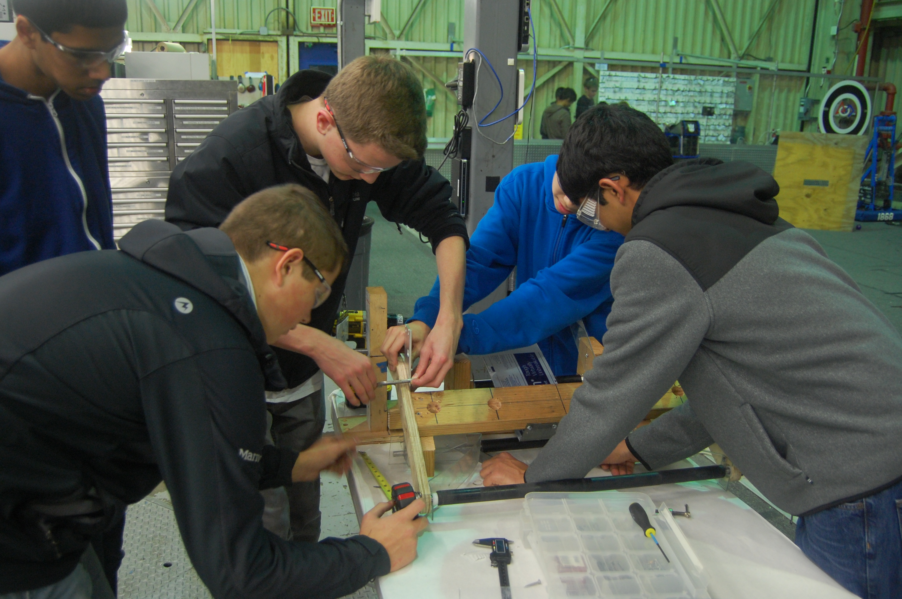
Students test different angles and heights using the wooden prototype
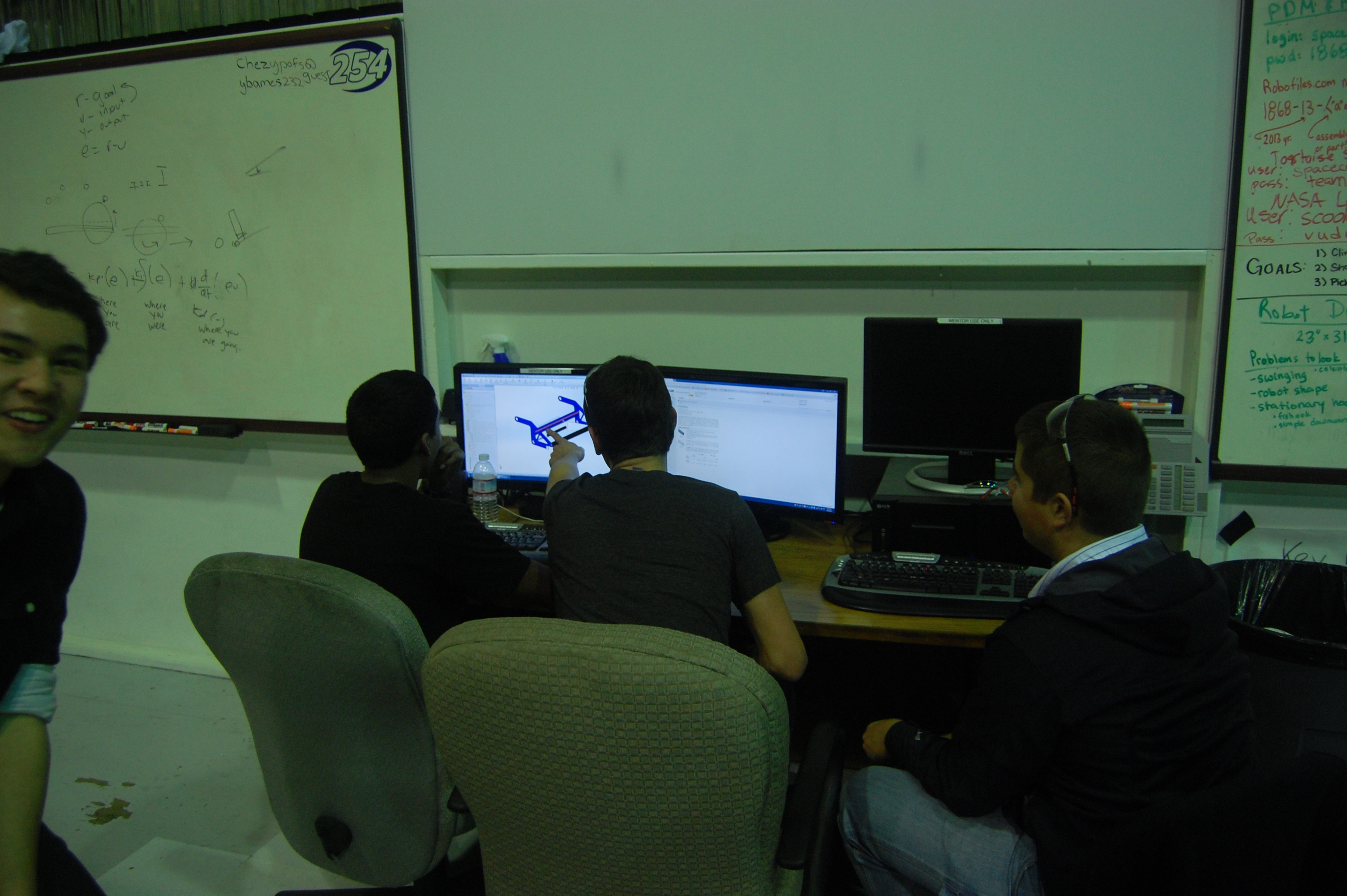
Students model the intake in Solidworks
Wiring
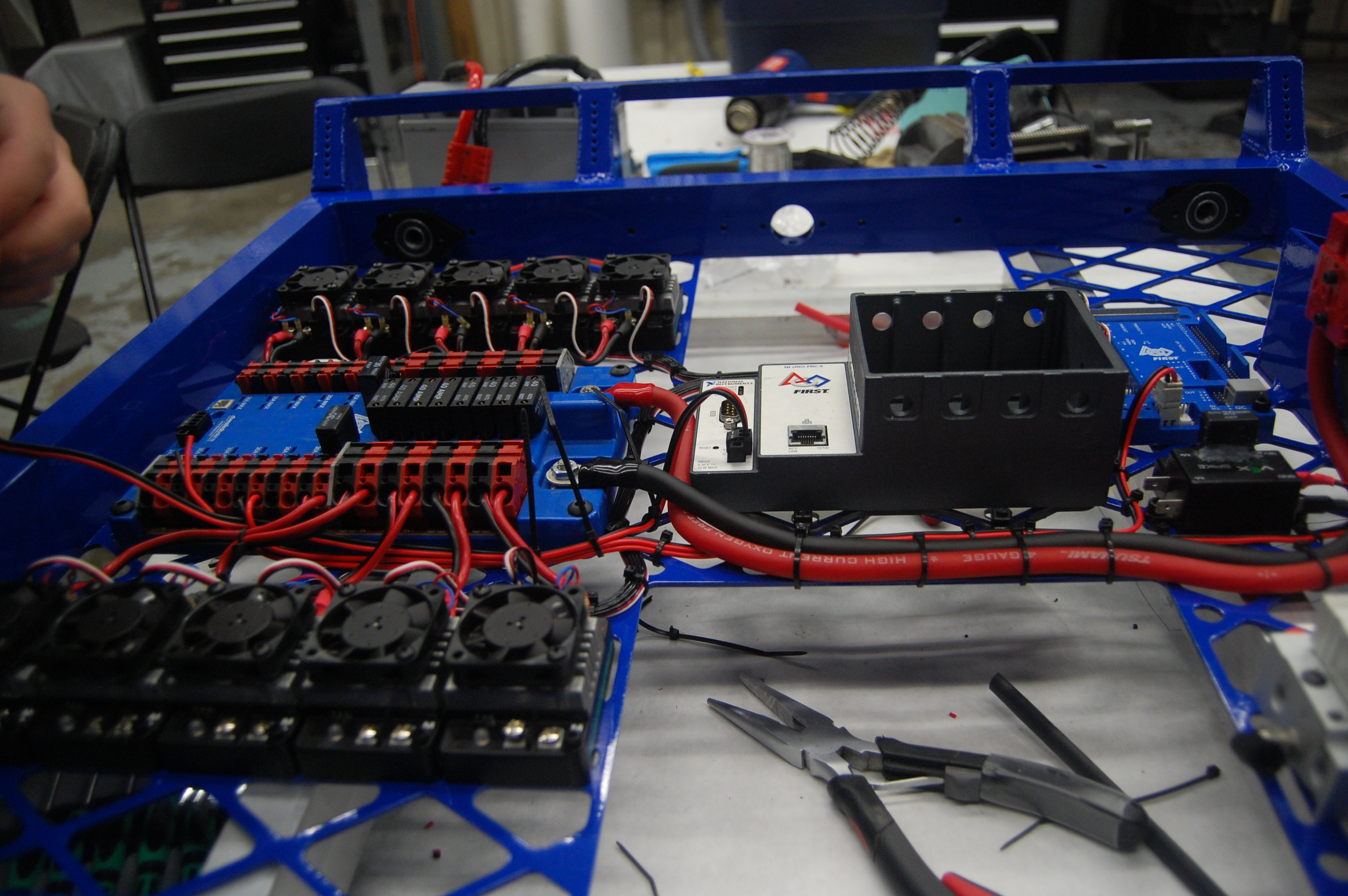
The students and mentors today worked on the electronics for the two chassis we got back from powdercoating. Currently on both the “practice” and “competition” robots, there are Power Distribution Boards, On/Off switches, Talons (speed controllers) and battery boxes. The team began wiring the Talons to the power distribution board.
Chassis with electronics
Programming
The programmers began the day by creating a command to shift the drivebase gearbox from high gear to low gear. This was done by creating a Solenoid object and switching it on or off with the press of a button. In addition, the students mapped four buttons on the gamepad (A, B ,X, Y) to the 2012 robot’s shooter. Each of the four buttons, when pressed, sets the shooter wheel at a predetermined speed. This implementation will be helpful for adjusting shooter wheel speeds on the actual robot this year.
Next, the programmers tried to come up with ways to display a graph of values from a Controller (speed, distance, etc) versus time. They brainstormed ideas on how to implement this, such as using the Smart Dashboard or a webpage. Students are looking into Flot, a jQuery library for plotting values on a dynamic graph. This graph will help with PID tuning and other testing.
Action Items
- Continue Wiring Robot Chassis
- Take steps toward a moving drivebase
- Continue on intake CAD/prototyping – Finalize dimensions
Lab closing time for the night was: 11:59 pm
Day #21: Prototyping & Wiring
Prototyping
Indexing
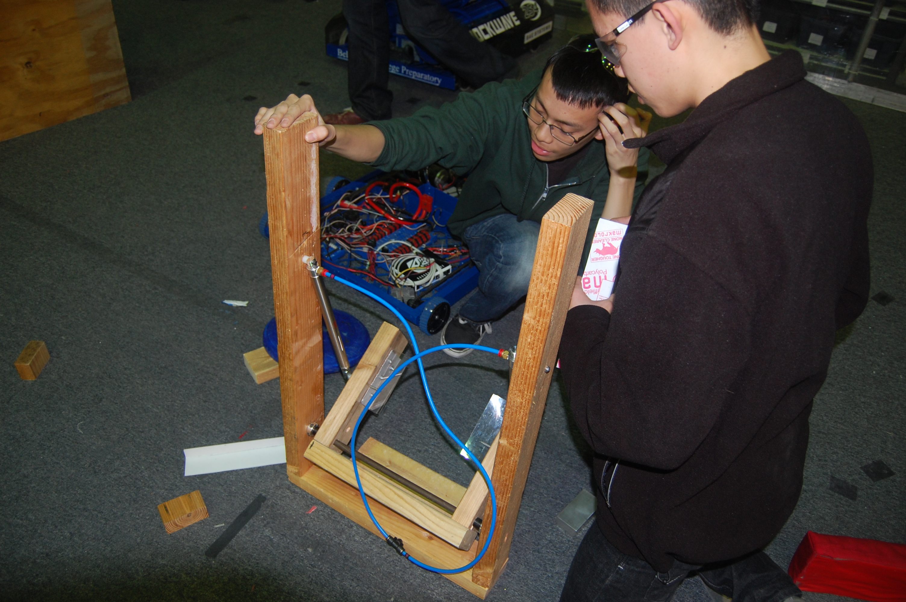
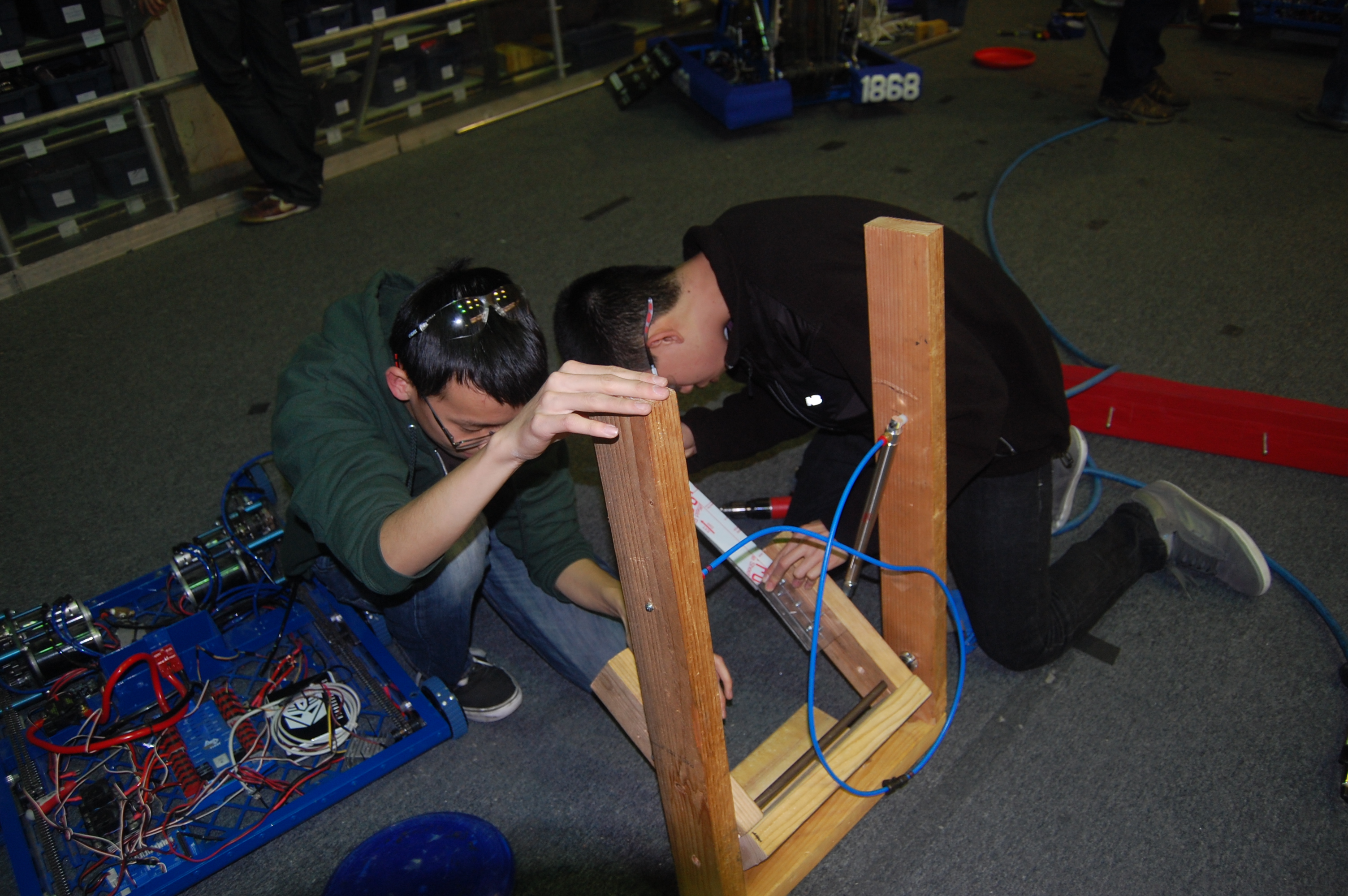
The intake prototype is taking shape. It is now at a point where it's working and we are almost ready to begin manufacturing. Along with the intake, the mechanism for transferring frisbees to the shooter is also in the process of being prototyped. This indexing mechanism will transfer frisbees from the intake and conveyor to load them up in the shooter. The prototype will use two pneumatic pistons to accomplish this. It doesn't yet work fully, but in terms of a proof of concept, in works fairly well.
Students building the indexing prototype
Wiring
The robot wiring was worked on today on both the practice bot and the competeition bot. The PWM cables from the Talons were wired and put in place and the relays were wired to the power distribution board.
Wiring on the drive chassis
Programming
The programmers did more work on control and filters. They created a "bang-bang" controller; unlike the PID contoller, the bang-bang controller runs the control source until it reaches it goal, and stops once the goal is reached. They used the control scheme to control the shooter wheel, which worked fairly well (aside from the funny noises of the motors going on and off). The students also used a Counter instead of an Encoder to represent the encoder sensor, as the period of the encoder can be retrieved to calculate the RPM of the shooter wheel. Next, they also wrote a moving average filter, which takes in a double as an input and stores it in an array. The filter would return the average of the inputs as a single output. This has not yet been used, but it is a good utility to have.
Finally, the programmers prettified the code significantly. Many Javadoc comments and style-guide-cohering formatting fixes were included in the prettification process.
Action Items
-
Finish and test indexing prototype
Lab closing time for the night was 10:00 PM
Day #21: Conveyor and Stuff
Conveyor
Today, students worked on the conveyor system. This is the part that will transfer the frisbee from the conveyor to the shooter. The frisbee is pressed into the polycarb, where it gets stuck due to two 30-degree hinges. Students first created an 11 x 11 inch box, then labored over the polycarb to get it just right, and finally unscrewed one of the sides of the square, creating a U shape.
. 
Week #3, Day Off
 Today was a good day, as far as Mondays go. The parts for our drive gearbox were picked up from Modern Machine Company. The PTO Shafts, Output Shafts, Intermediate Shafts, and Wheel Shafts (small and medium) were returned. They turned out great! All that is needed to finish assembling the gearboxes are the parts from West Coast Products. Once those parts are received and the gearboxes are assembled, the drivebase will be driveable for the first time.
Cory and Pat worked on getting the new lathe working, which is running, but not currently useable as a main machine.
The season is going well and manufacturing is ahead of schedule. Design, on the other hand, is behind schedule. There will be a design freeze and a Order freeze on Friday. That means the design will be completed by the end of the week and all the known parts needed will be ordered by Friday.
Build Season Recipes: Week 3
The nutritional benefits from the intake of these brownies helped us finalize our intake geometry over the weekend.
Non-Strategy Brownies
-
1 cup butter, melted
-
1 cup sugar
-
1 cup brown sugar
-
3/4 cup cocoa powder
-
1 1/2 tsp. vanilla extract
-
3 eggs
-
1 cup flour
-
1 1/2 tsp. baking powder
Mix melted butter, sugars and cocoa. Add vanilla and eggs; beat. Add flour and baking powder and mix well. Pour into a greased 9"x13" pan and bake at 350°F for 20-25 minutes, or until an inserted toothpick comes out with fudgey crumbs. Best enjoyed served warm with vanilla ice cream.
Day #22: Prototyping & Intermediate Shaft Spacers
Machining
The students and mentors finished machining the intermediate shaft spacers. After ordering gear box shafts from a sponsor, the team decided to manufacture twice as many to take the PTO into account. Because we are not able to manufacture a hex into the round part of a shaft with the tools at the lab, students are instead making our own out of a hex shaft and placing a spacer on one end to prevent the gear from moving. Members also unsuccessfully searched for hex bearings from the storage crates.
![IMG_20130129_220806[1]](http://media.team254.com/2013/01/1d5c0478-IMG_20130129_2208061.jpg)
The newly manufactured shaft spacers
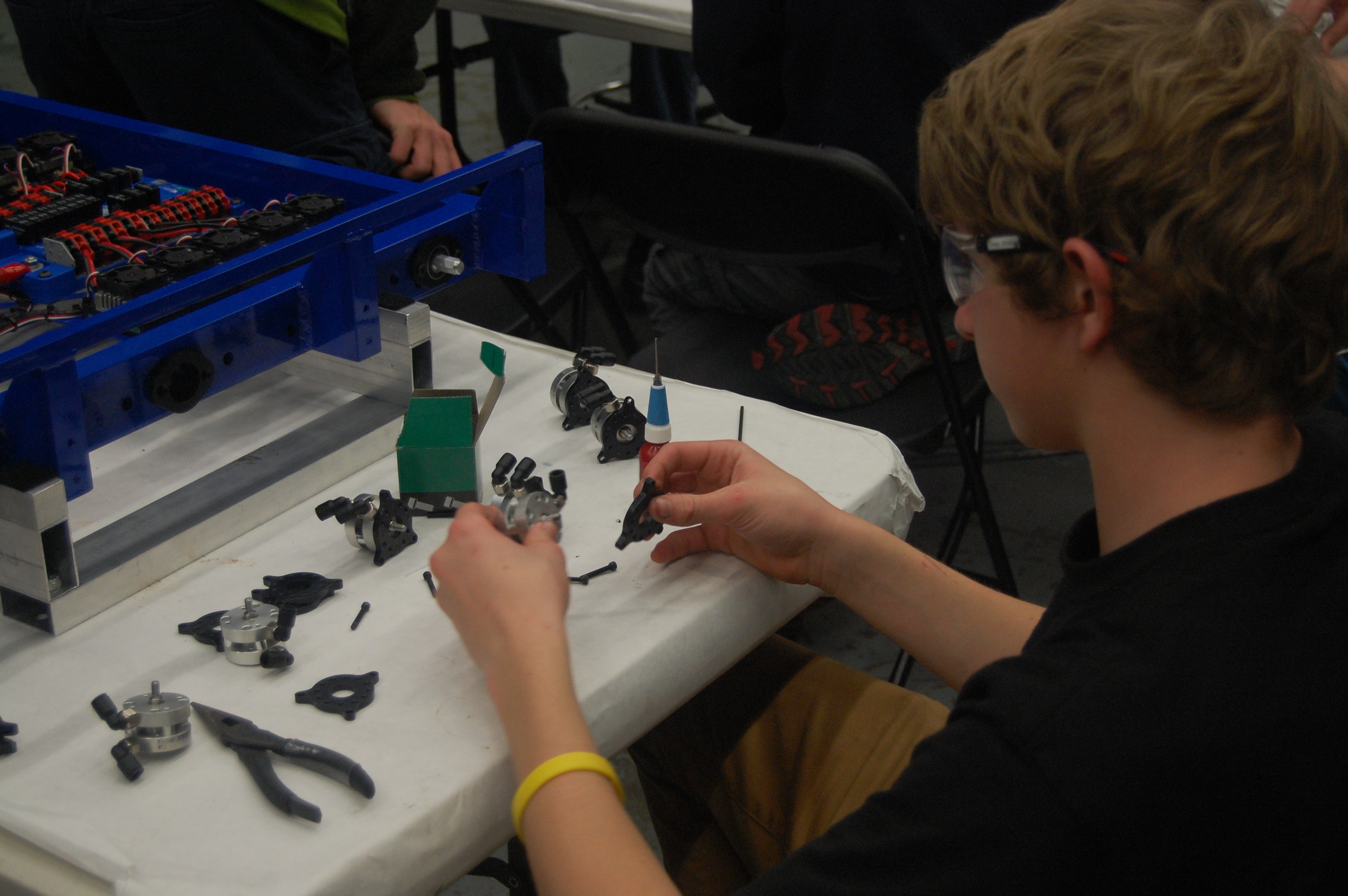
Prototyping
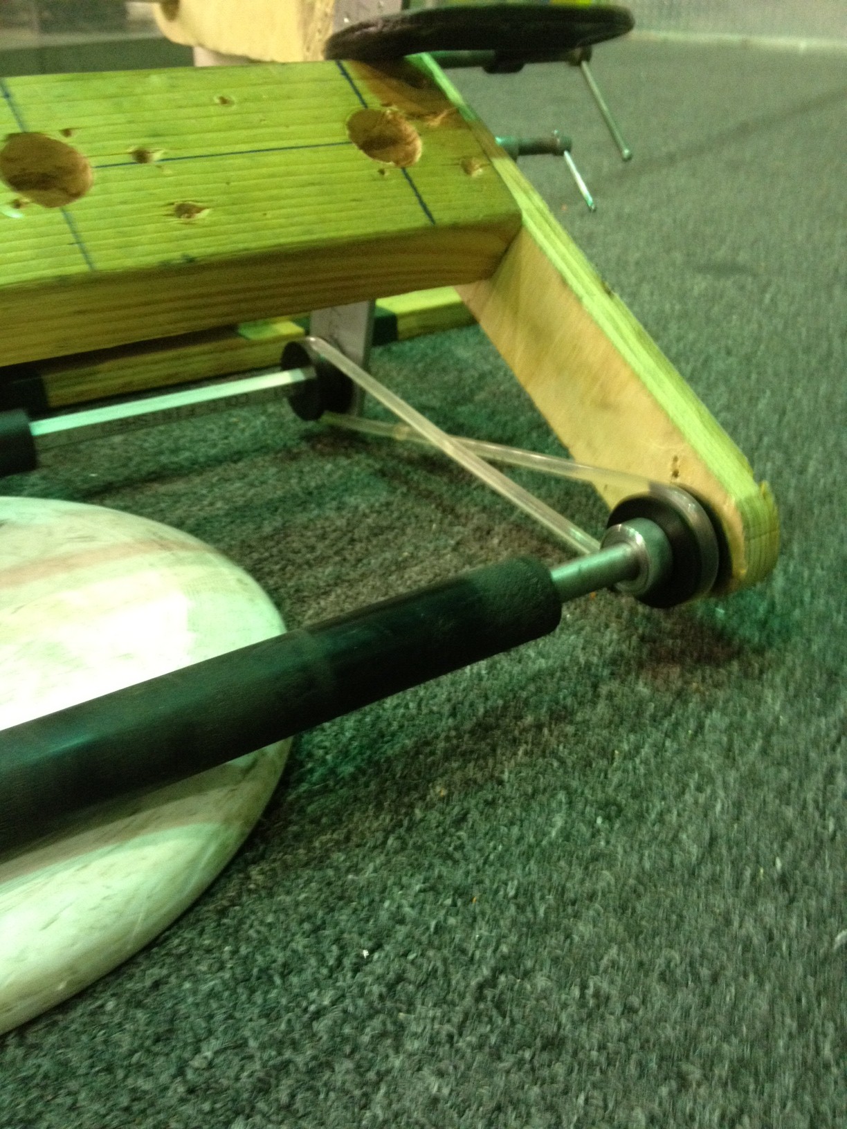
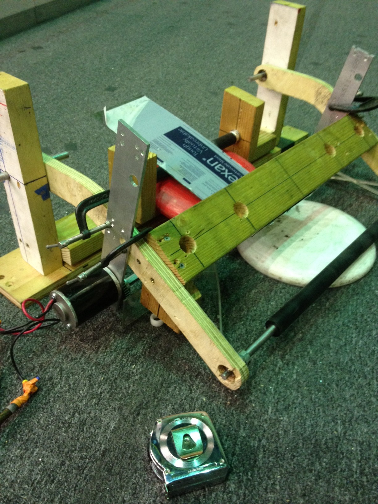
Students also worked on the shooter indexer. The two side blocks for the outer indexer had to be replaced, as the previous wooden blocks were not long enough. Students successfully got the shaft through both parts of the prototype, such that the smaller one can pivot. The next step for this project is to attach the pneumatic pistons to the main frame of the prototype.
![IMG_20130129_220706[1]](http://media.team254.com/2013/01/23d204cd-IMG_20130129_2207061.jpg)
Students assembling the shooter indexing prototype
![IMG_20130129_220720[1]](http://media.team254.com/2013/01/1faf04f9-IMG_20130129_2207201.jpg)
The intake prototype
Programming
The programmers tested the gyro and were able to get accurate results from it. They also retrieved the two S4 drive encoders from Skyfire for future use and storage. In addition, they finished translating the state space controller from C++ to Java. Though the new code has not yet been explicitly tested, it compiles fine. More tests will be done at a later time.
Next, the programming team tested out the bang-bang controller, which controls the 2012 robot’s shooter wheel. They also tested the graphing tool within the Smart Dashboard and made it display the velocity of the shooter wheel versus time.
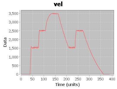
Velocity (rpm) of the shooter wheel vs. time
Action Items
- Finish constructing shooter indexing prototype
Day #23: Wiring and Prototyping
Wiring
Wiring the main robot chassis was continued today, as students and mentors mounted and wired 8 port solenoids. As well, the spike was wired and progress was made in the decision on how to mount the compressor. With majority of the base wiring complete, the team is currently waiting on new cRIO modules to arrive so that they can be mounted and wired as well.
Wiring the solenoids
Prototyping
Prototyping was divided into multiple subgroups today, with students working on the loading mechanism, the conveyor, as well as mounting a mini CIM motor to power the intake prototype.
Loading Mechanism
A select group of students decided to prototype the loading mechanism which transfers the frisbee from the conveyor to the shooter. Using polycarb, wood, and pistons, they were able to manufacture a working prototype to serve as a successful proof-of-concept reinforcing designs already implemented into CAD.
Conveyor
Students worked to make a conveyor out of wood to use as a proof-of-concept with using 3/8″ hex shafts versus the previously favoured 1/2″. It is still a work in progress and is currently being assembled.
Intake
It was decided that to optimize the speed of rollers used in the intake, it is neccessary to modify the current intake design which had previously been powered solely by pneumatic drills to operate using a single mini CIM motor. To do so, students created 2 pulleys to direct power to the front rollers using polycord while the back rollers will be powered by gears at a 3:1 ratio. There was minor setbacks in the broaching of a 1/2″ gear, and as such the project was slowed. The modifications are still currently underway and will be documented in depth once they are completed.
Last night the intake prototype was modified to have both rollers powered by a mini-CIM, as shown in the photos below. The gears mentione above were used to power the bottom roller. This resulted in a theoretical max surface speed of 9.8 ft/s. When the frisbees were put through, there was virtually no observed speed reduction in the CIM due to the load. Because of this, it is alright to gear the intake for 18 ft/s theoretical surface speed, so this design will be proceeded with.
The front intake roller, connected with polycord
Both rollers powered by a mini-CIM
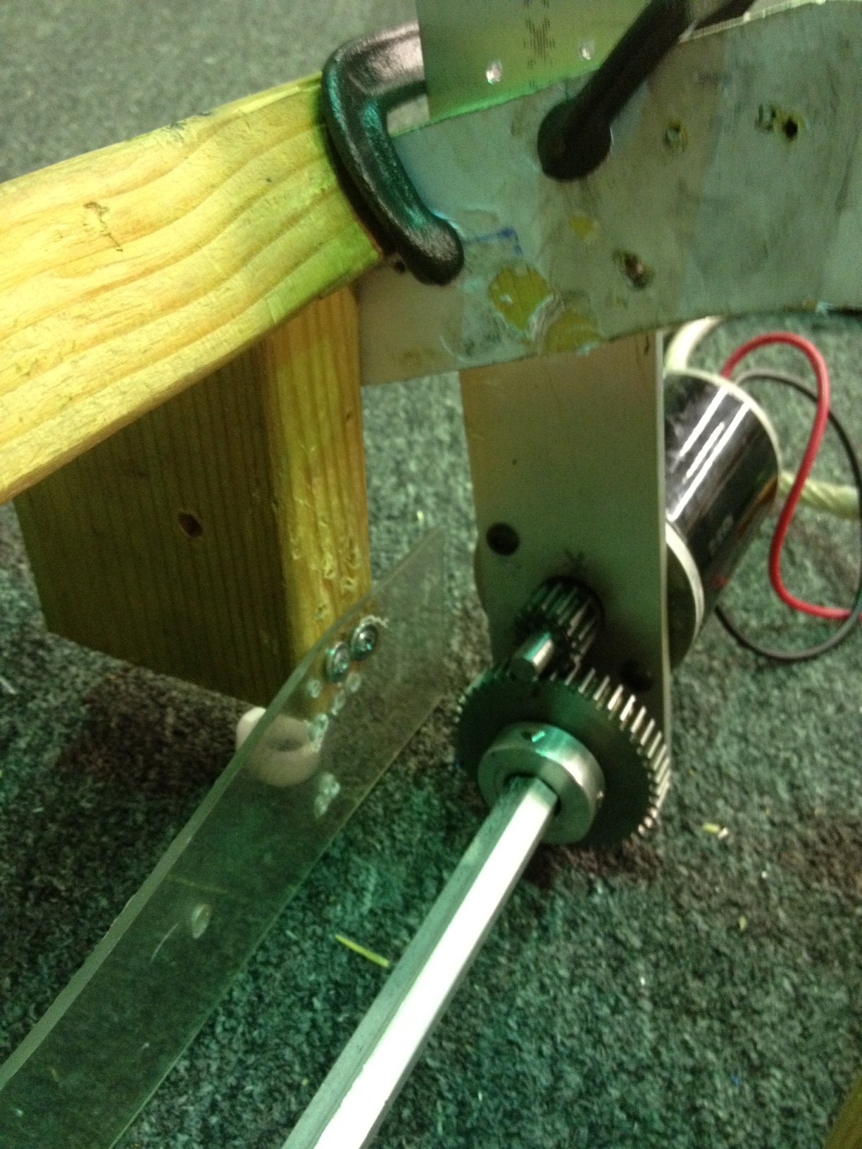
Bottom roller, with 3:1 reduction
Brogramming
The programmers continued graphing the 2012 robot’s shooter wheel RPM versus time. They experimented with both the bang-bang controller and a PID controller, as well as with and without a moving average filter. When using the bang-bang controller to control the shooter wheel, students found that using a moving average filter to filter the motor outputs produced smoother and more consistent results. The programmers spent a lot of time adjusting the P, I, and D terms of the PID controller. Though the PID controller’s graphs are relatively more stable and smoother than the graphs of the bang-bang controller, the PID controller either tends to overshoot its goal or to not reach it at all (mostly at 3500 rpm).
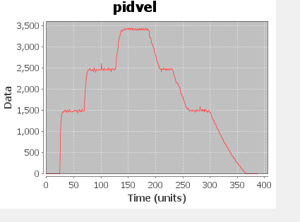
Graph of a PID-controlled shooter wheel (P = 0.007, I = 0.0, D = 0.003)
Action Items
- Get a quote on wood for bumper assembly
- Buy wood/cordura for bumper assembly
- Finish design changes on conveyor and intake assemblies
- Finish prototyping conveyor
- Start designing control board
- Start manufacturing bumper components
- Hook up a speed controller to the intake to figure out the minimum required torque.
- Measure the current draw with the ammeter.
Day #24: Bumpers, Wiring, and Continued Prototyping
CAD
Students made some of the drawings for the conveyor shafts. The shafts with finished drawings should be finished tonight.
Manufacturing
Students manufactured a few of the shafts for the conveyor assembly. These hex shafts will used with the polyurethane rollers to move the frisbees from the intake to the piston-powered loader.
Manufactuing parts on the lathe
Bumpers
Students began measuring the dimensions of the bumper cordura based on the measurements of the robot bumper assembly in Solidworks. They will order 4 yd x 60 in cordura material from Seattle Fabrics for the red and blue bumpers. Particular effort will be spent making sure that the colors are according to the team standards. After confirmation of all details, they will place the order.
Wiring
Wiring today consisted of soldering connectors onto a mini CIM motor and another set of connnectors for the speed controller to test out the intake prototype. The students discovered that the motor’s shaft was spinning, while the gear was not. After some modificaitons, the team was able to successfully control the speed of the intake with the speed controller, which was mapped to the Logitech gamepad.
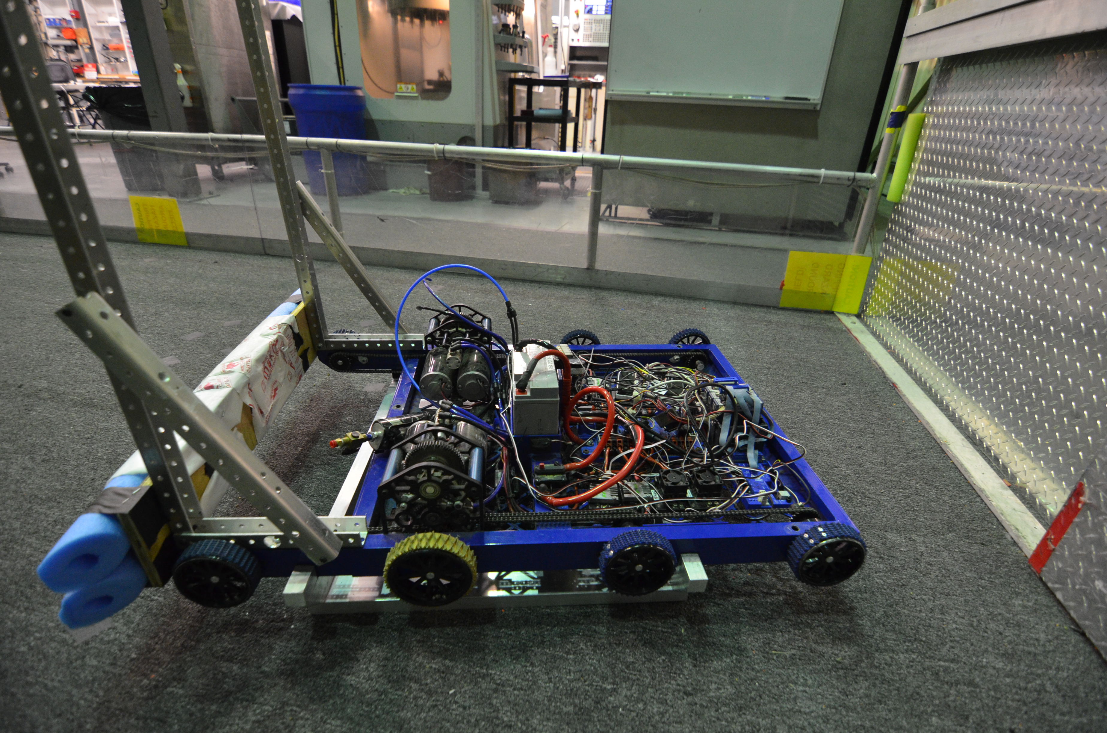
The current drivebase chassis
Prototyping
Students continued design on the intake, revising the polyurethane rollers as well as the polycarb on top. This wasn’t worked on much today, but the improvements drastically increased efficiency.
Student making adjustments to the intake
PR
Students continued to revise Chairman’s as well as work on various sponsor things. Awards will be delivered later this week, and prospective sponsors are being contacted.
Programming
Today, the programmers continued work on tuning the PID controller for the shooter wheel. The results were roughly about the same as yesterday’s results. When the actual shooter is built, the team will spend a great deal of time to tune the shooter controller very nicely and accurately. But for now, this was a good exercise and experience the team can learn from. The programmers are currently experimenting with a mix of filters, different controllers (bang-bang vs. PID), and feed-forward.
Meanwhile, other programmers wrote code for the intake prototype. They mapped it to the Logitech gamepad, so that the shoulder buttons would increment or decrement the speed controller output by 0.005, the start button would set it to 0.0, and the back button would set it to +1.0. This functionality was requested by the students working on the intake prototype, since they want to find the minimum required torque to intake a frisbee smoothly. Tests are currently being conducted on this.
Programmers intently programming
Day #25: Manufacture of Conveyor and Shooter Begins
Drive Gearbox
The bulk of the remaining parts ordered from West Coast Products arrived today, including gears, shifting dogs, and shifter shafts. Students assembled the piston blocks for the bimba pistons. This will actuate the dog shifters, which will control the 2-speed transmission and PTO. The dog shifters were modified to prevent interferences and fit inside the gearbox.

Machined Shifting Dogs
Shooter and Conveyor
Students made drawings for shafts and spacers that will later be used on the shooter and conveyor. The raw materials for these parts were cut, and later manufactured by students with assistance from the mentors.

Makin the Pahts

Finished Parts
Programming
Students worked on the code for the intake. They also tested all the subsystems of code to make sure that they functioned properly.
Visitors!
Team 100 from Woodside, Carlmont, and Sequoia High Schools visited the lab today. They stopped by for a couple of hours to borrow the use of the lab’s hex broach.
Action Items:
- Assemble Drive Gearbox
- Continue manufacturing Shooter and Conveyor shafts
- Release more parts for manufacture
- Further develop code
- Wire Pneumatics
Lab Closing Time: 12:30
Day #26: Practice Robot is Driving
Much progress today was made in manufacturing and assembly, and near the end of the evening the practice robot was driving for the first time.
CAD
Abhi and Richard M worked on detailing the intake assembly, with the goal of releasing all parts for manufacture by the end of the weekend. The gearbox design is still in progress, but gear ratios have been finalized and gears and timing belt pulleys selected to yield surface speeds of 17 fps on the first (top) roller, and 18 fps on the second (bottom) roller and conveyor. The higher second roller speed is necessary to clear discs from the intake more quickly when multiple discs enter simultaneously, and the conveyor must move discs back through the robot as fast as the second roller feeds them in.
Manufacturing
Students and mentors continued working on the shooter and conveyor parts that were released to manufacturing yesterday. Josh finished the conveyor frisbee back stop pins by adding a radius using the “CNC lathe file” technique. Connor, Chris and others started the conveyor middle hex shafts and conveyor bottom standoffs. Many other students cut stock material to rough lengths on the horizontal bandsaw throughout the day to keep the lathes and CNC supplied. Pat made the two different shooter shafts on the newly-functioning Monarch lathe, while Cory manufactured square plugs on the CNC to be inserted and welded into the square tubes that span the width of the intake.
An issue was discovered with the VEX ½” and ⅜” hex shafts received near the start of build season; many of them are visibly crooked, which is causing runout on the machined parts. E-mails exchanged about the issue with the President of VEX Robotics led to the conclusion that this was possibly an isolated incident due to the way the shafts were shipped (in a flat package instead of a round tube). More shafts are already incoming from VEX and the existing ones can be sent back for exchange. Hex shaft held against a flat surface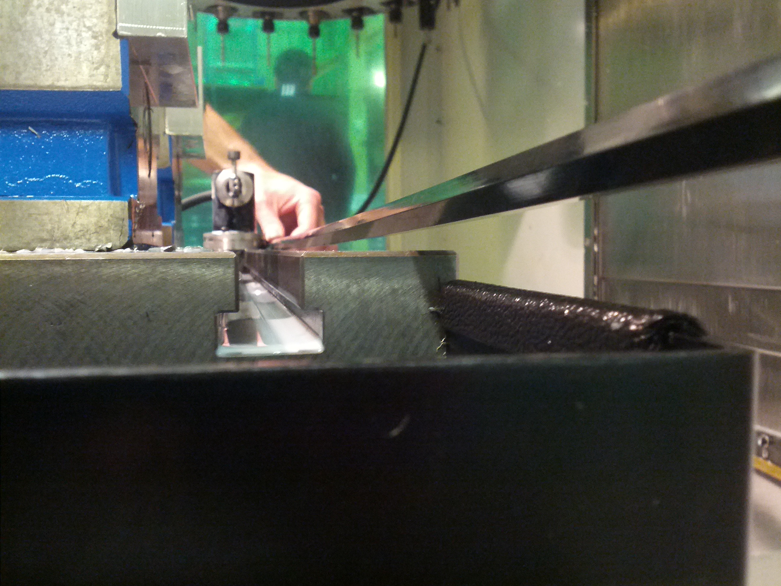
Assembly
Although not all the parts that will be used in the competition gearboxes have been received yet (a few anodized gears are still missing), a few gearboxes were partially or fully assembled using substitute parts. It was discovered that the CIM output shaft spacers already made were not long enough as the WCP pinions do not have hubs like the steel pinions used in previous years, so new spacers were made.
Robert and EJ assembling the gearboxes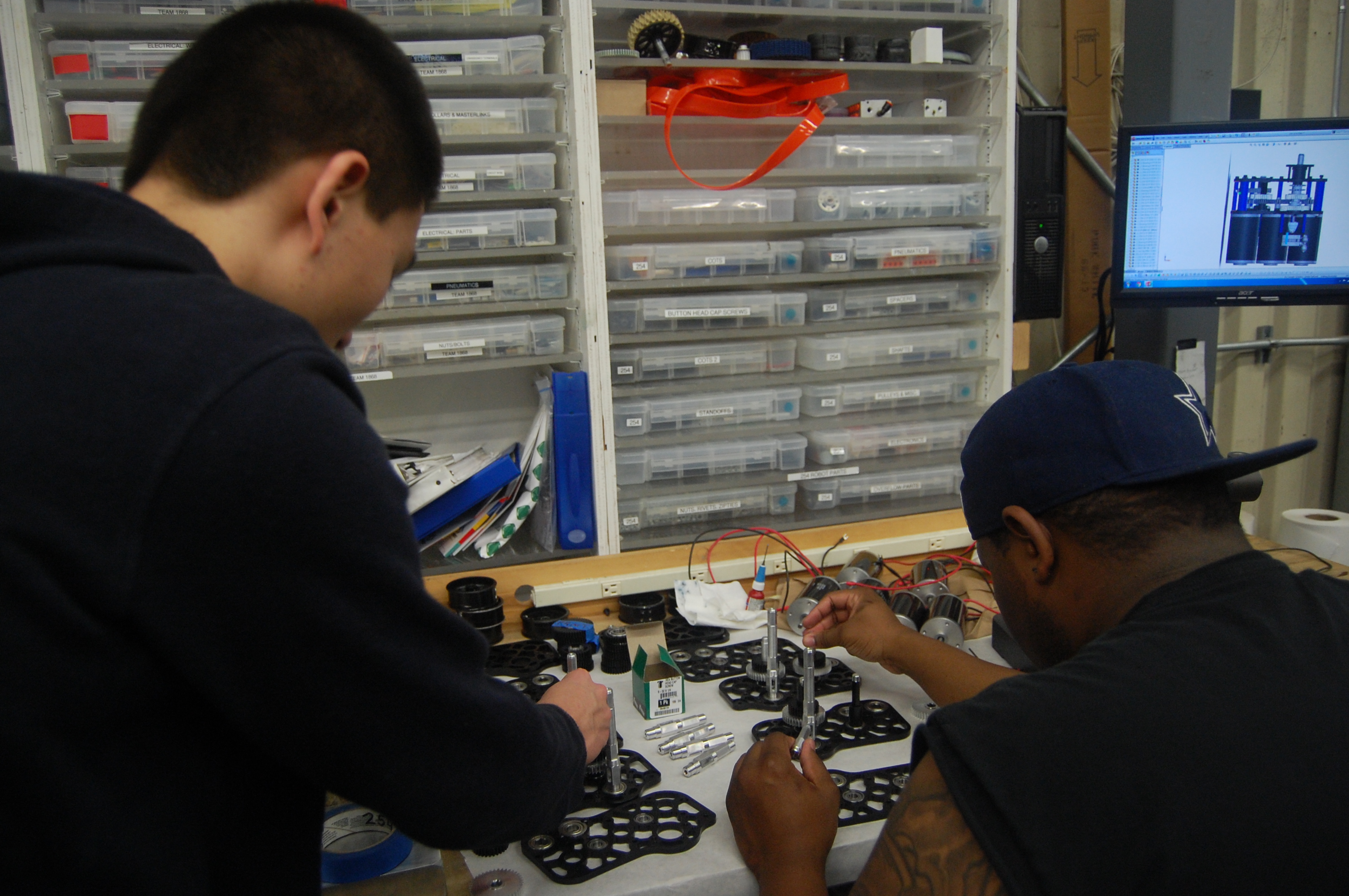
Wiring
Not much wiring work was done on the competition robot as some parts (new cRIO, ribbon cables) are still missing, but enough was done on the practice robot to enable it to run. The ribbon cable going between the digital sidecar and the cRIO was added, and power was run to the analog breakout. Additionally, to enable testing, a D-Link radio and 12V-5V converter were hacked on (but will likely be moved to different locations later). Nagy and Francisco also crimped and soldered terminals to all the CIM motors.
Terminating the CIMs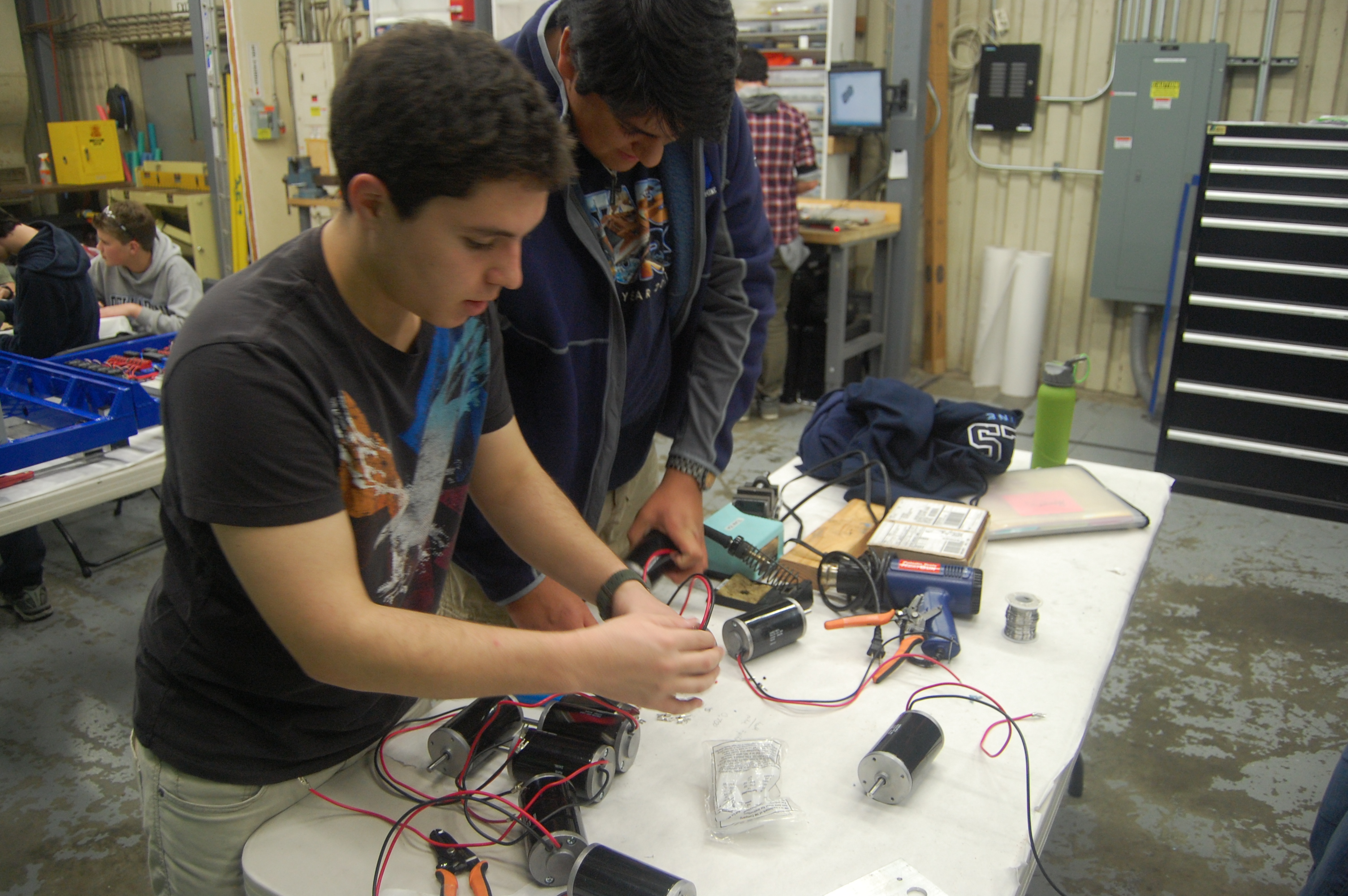
The team received a visit today from Matt Pasienski, who works at one of the team’s sponsors, Ooyala, and has coached Ultimate Frisbee at the national college level in addition to holding a PhD in Physics. He spent time with the primary and backup human players, Aaron and Nagy, and helped them refine their hammer-throwing technique.
Matt coaching Aaron on how to throw a hammer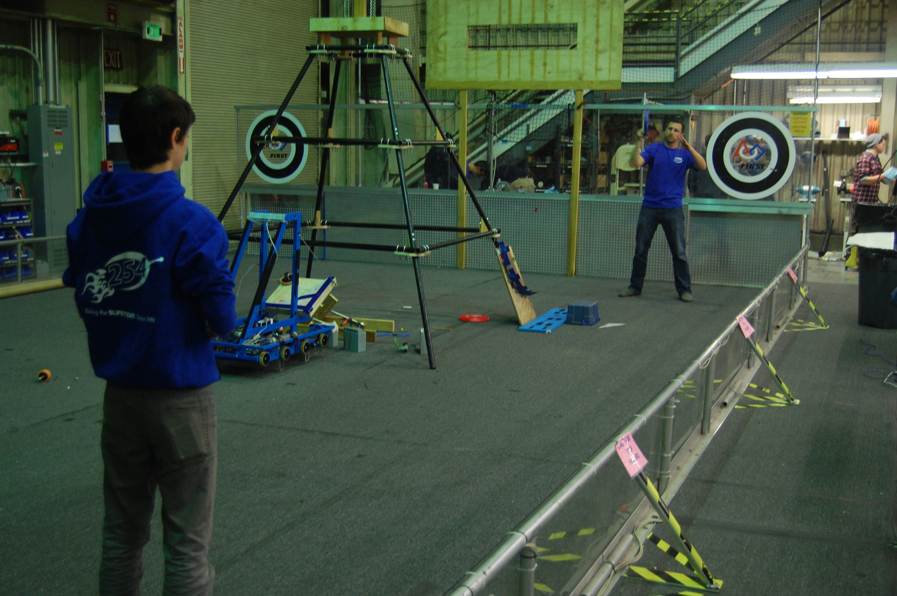
Robot driving
Final assembly and wiring of the drivebase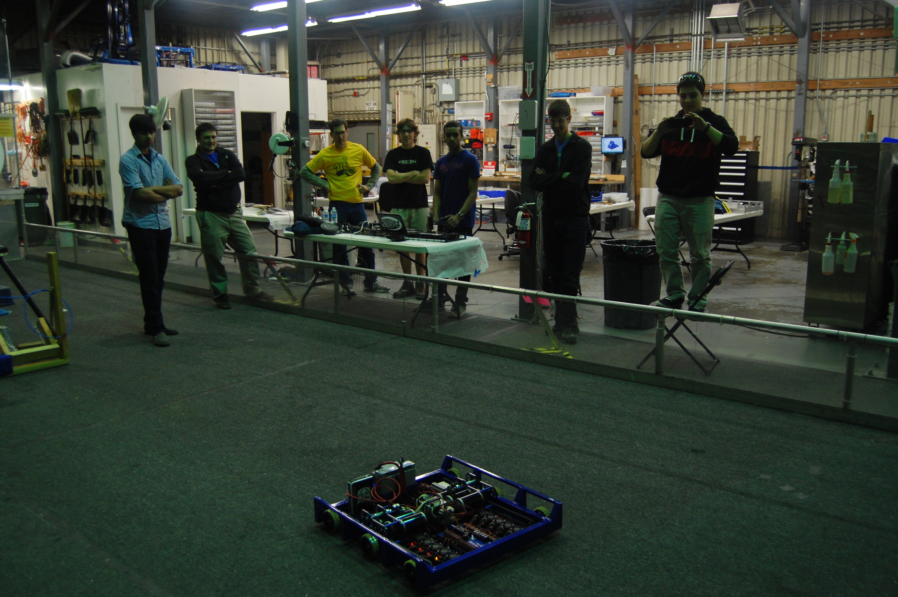
As the pneumatics are not yet plumbed or wired, the shifters were locked into high gear with a couple of zip-ties each. After a few false starts (the cRIO was wired to a 12V power source instead of the 24V, the analog breakout wasn’t receiving power properly, and the joystick trim tabs weren’t centered), the programming team quickly got the drivetrain running with the robot in its stand on top of a table. After calibrating the Talons, the robot was put down on the field at about 11:15pm and taken for a test drive by Abhi and a few others. The practice robot’s maiden voyage
Action items
-
Complete manufacturing conveyor middle roller shafts and bottom standoffs
-
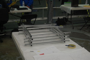
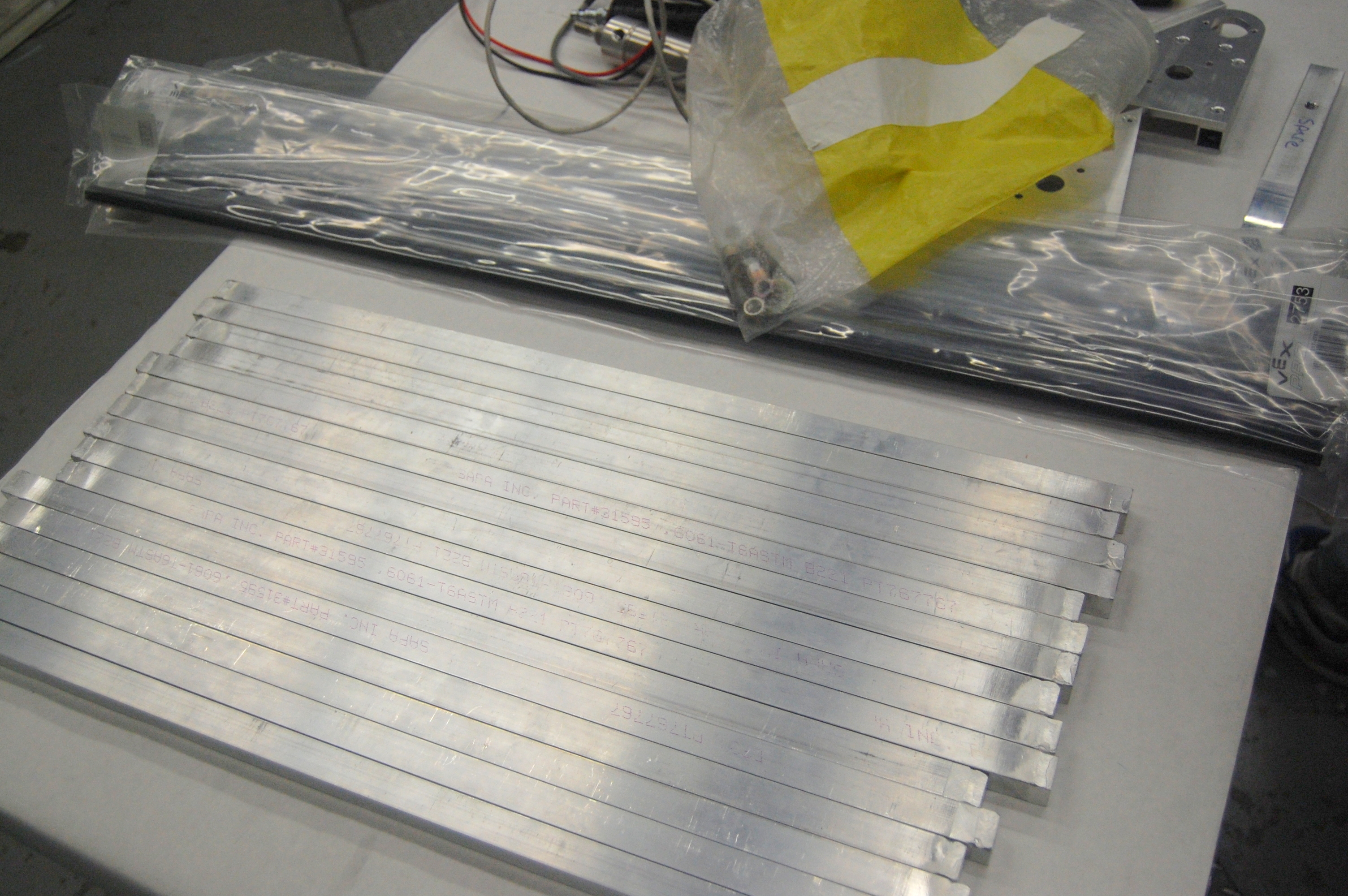
Cut all aluminum tubing needed to be sent out for superstructure/subsystem welding on Monday
-
Make drawing for superstructure plugs and machine them on the manual mill
-
Begin driver drills with the practice robot
-
Wire and plumb pneumatics on both robots
-
Continue competition robot wiring
-
build
Lab closing time: 2:00am
Day #27: Superstructure
Wiring
The wiring on the practice bot was fixed because it was routed incorrectly and they were in the wrong ports.
Manufacturing
A large portion of the raw material for the superstructure was cut today. Some of the actual machining started which included drilling holes and tapping them so that they would be ready to attatch to the superstructer once it is ready. Some of the superstructure parts are being milled to length.


Completed super structure parts
Programming
Today, the programmers made miscellaneous changes and fixes to the 2013 code. The commands’ timeout functionality was changed to use the built-in setTimeout and isTimedOut functions, rather than creating an instance of a Timer and calling get(). This was tested and worked quite nicely and as expected. Additionally, the code was edited greatly to adhere to the style guide.
Build Season Recipes: Week 4
Our robot this year is looking like it will be very short — much like these shortbread cookies we snacked on while assembling the drivetrain and manufacturing parts for the intake.
Chocolate Chip Shortbread Cookies
-
1 cup butter, at room temperature
-
2/3 cup icing sugar
-
1/2 tsp. vanilla extract
-
2 cups flour
-
3/4 cup mini chocolate chips
Beat butter, icing sugar and vanilla until very smooth. Slowly add flour, mixing only until it disappears into the dough. Stir in chocolate chips by hand. Roll out dough between two sheets of parchment paper into a 1/4" thick rectangle. Refrigerate until solidified (about 2 hours). Cut dough into 1 1/2" squares and place on cookie sheet. Bake at 325°F for 18-20 minutes until golden brown around the edges.
Day #28: Auto Scripting and Bumpers
Bumper fabric
A few members measured fabric for the bumpers and measured where to properly place the team logo on them. They were careful with measurements because the ideal bumpers are more compressed than actual ones that will be.
Measuring the cordura
Wiring
Members starting wiring the cRIO on the competition robot. They also started wiring the encoders on the practice robot.
CAD
Members and mentors looked through all parts in the CAD and placed the rest of the part orders.
Parts
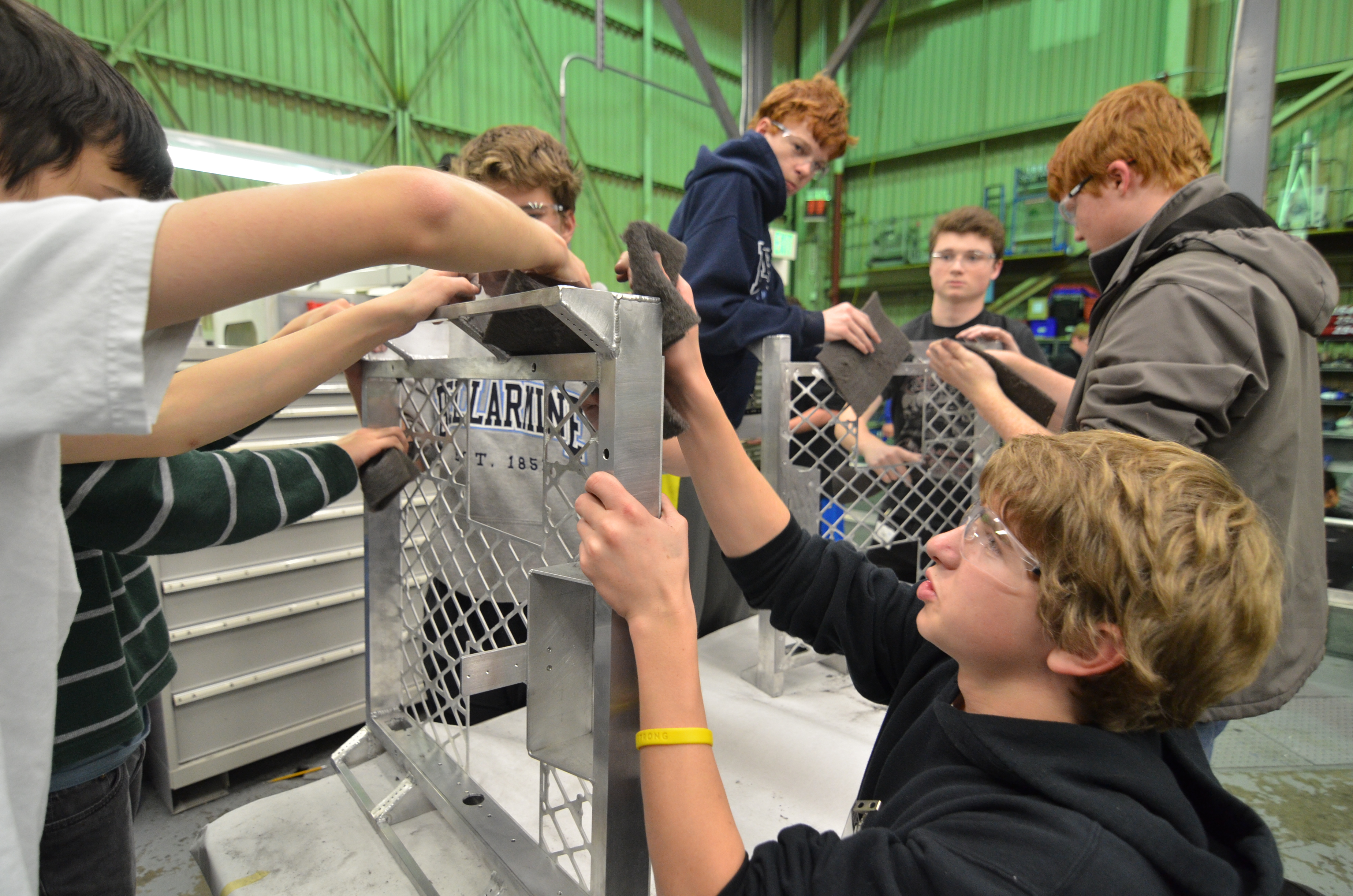
The team received the welded intake mounts and crossbars from sponsor Central Concrete. The welding left some rough edges, so some members and mentors used the pneumatic grinder to smoothen sections on the intake mounts. Overall, the welds turned out great and the assembies seem to be extremely strong. The team was a little disappointed in the welding on the intake mounts. It was very “globby” and had a lot of excess metal that didn’t seem necessary. After a bit of cleanup, it looked better. Hopefully the intake mounts will maintain their structural integrity throughout the competitions.
Crossbars
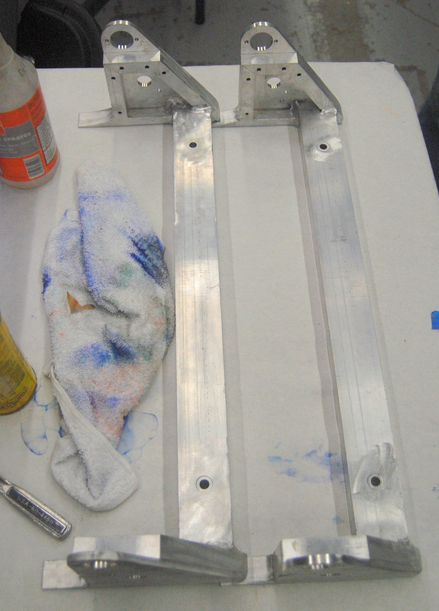
Intake mounts
Programming
The programmers worked more on the autonomous scripting. They added a feature to the auto command file reader that allows the user to denote whether commands should be executed sequentially or in parallel.
They also began work on a testing system that cycles through and briefly runs each of the six drive CIMs of the robot. The purpose of this is to test these motors of the robot and isolate problems before competing, allowing the team to diagnose and act on the problem. For example, the pit crew could activate this to verify that the drive motors function properly before matches.
Action items
- Finish wiring the competition robot
- Finish wiring encoders on the practice robot
- Cut bumper fabric
- Document auto script file format
- Finish code to cycle through subsystems
