FIRST Robotics Blog
FRC Day 15 Build Blog
Day 15: Drivebase, Prototypes, and Program
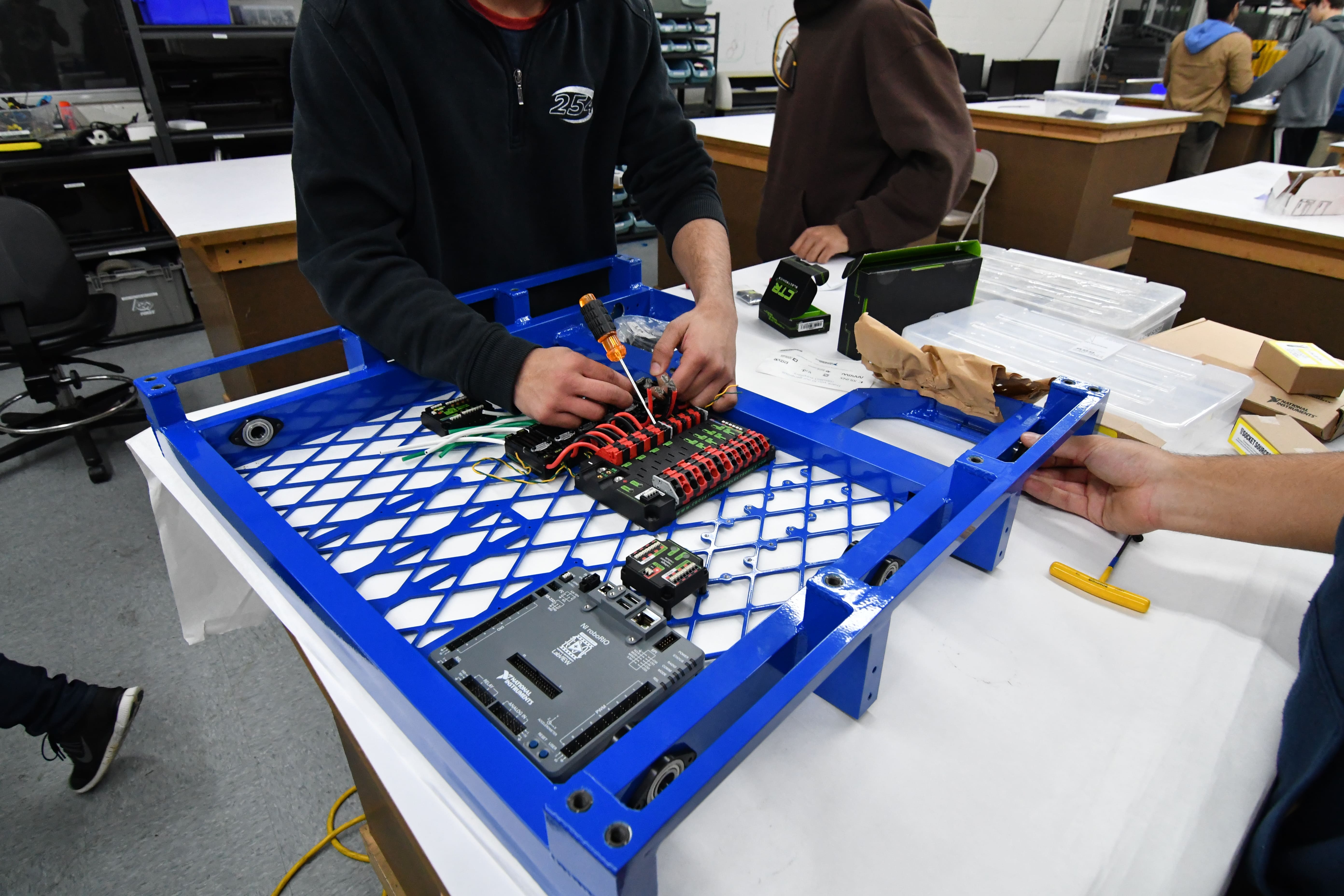
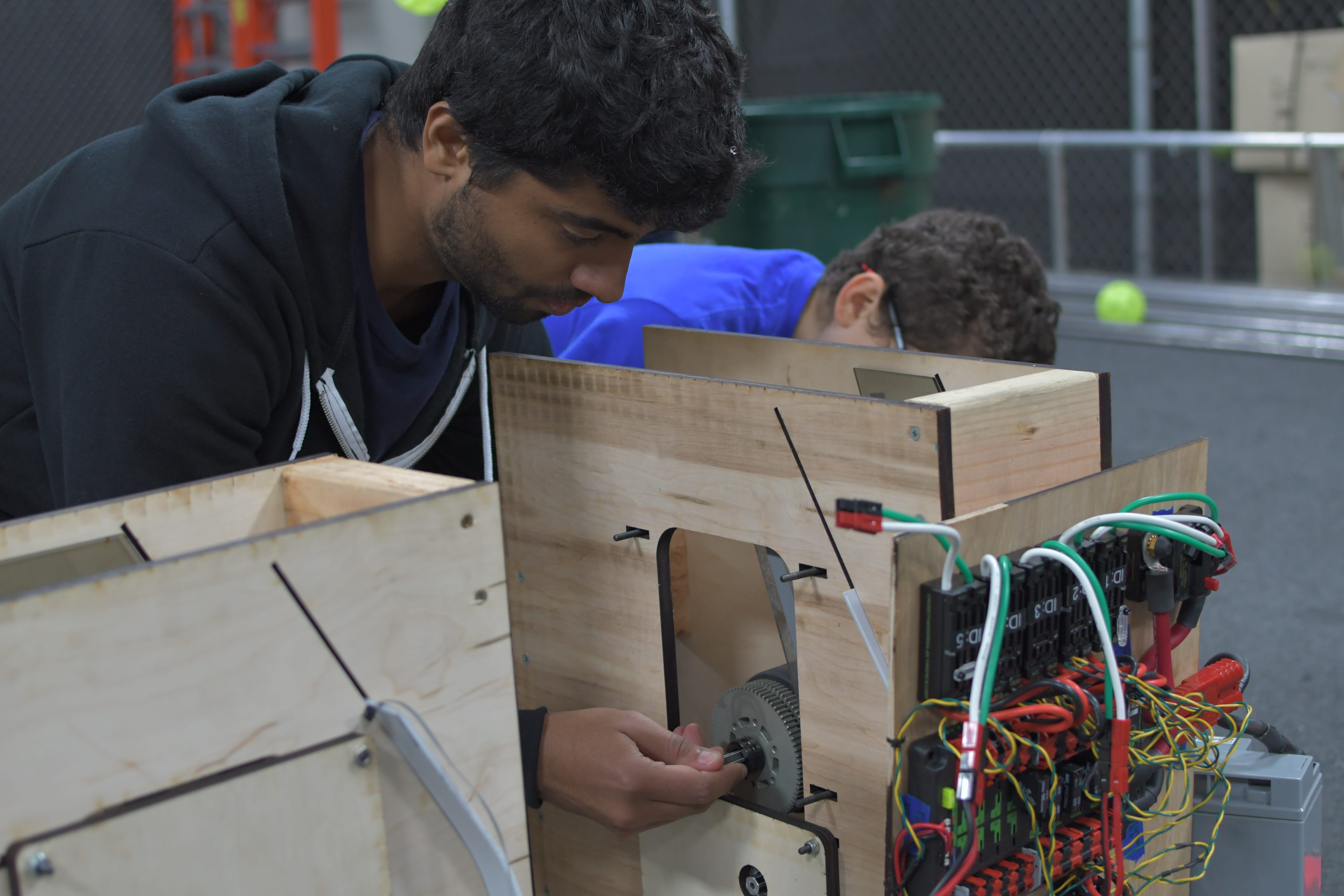
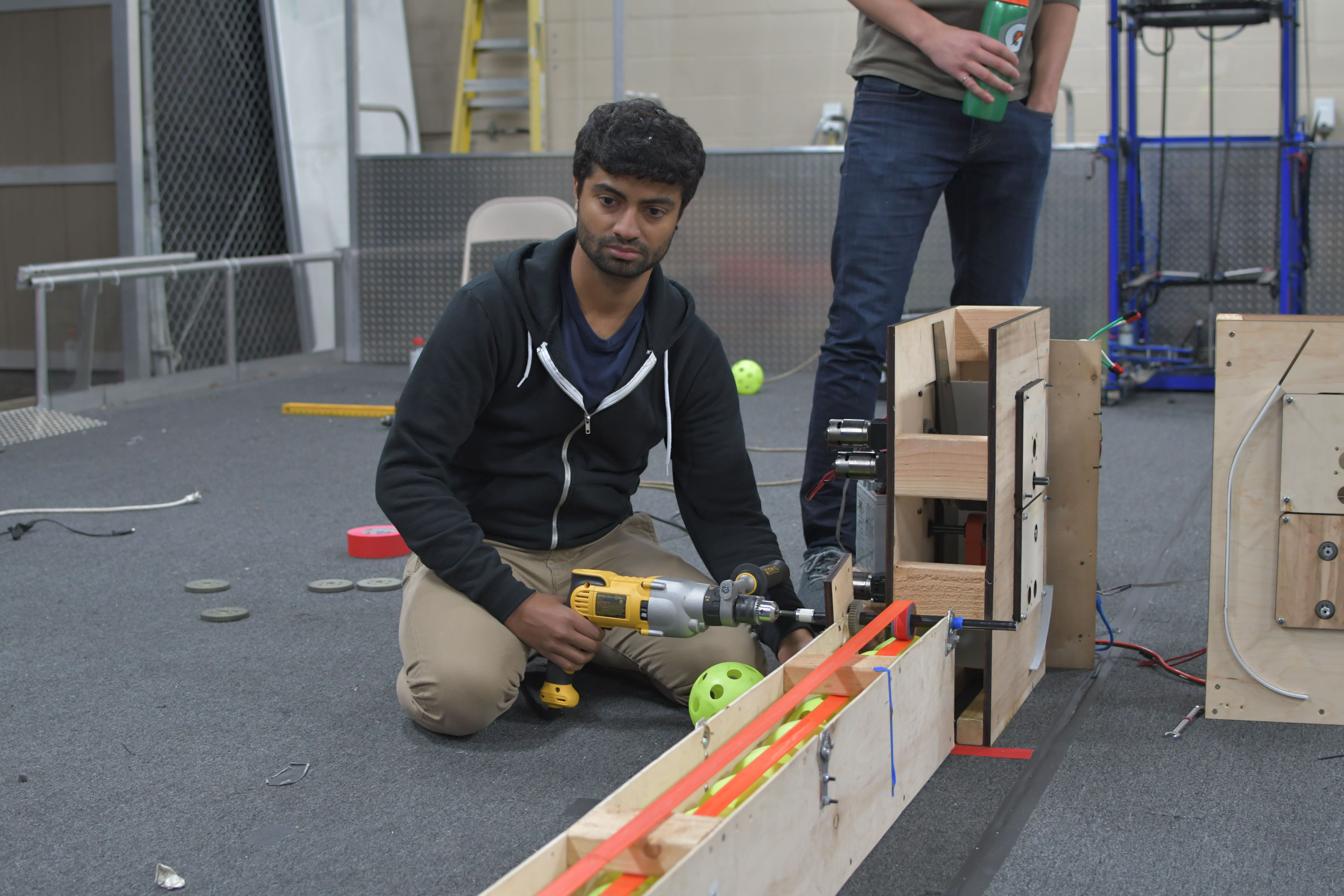
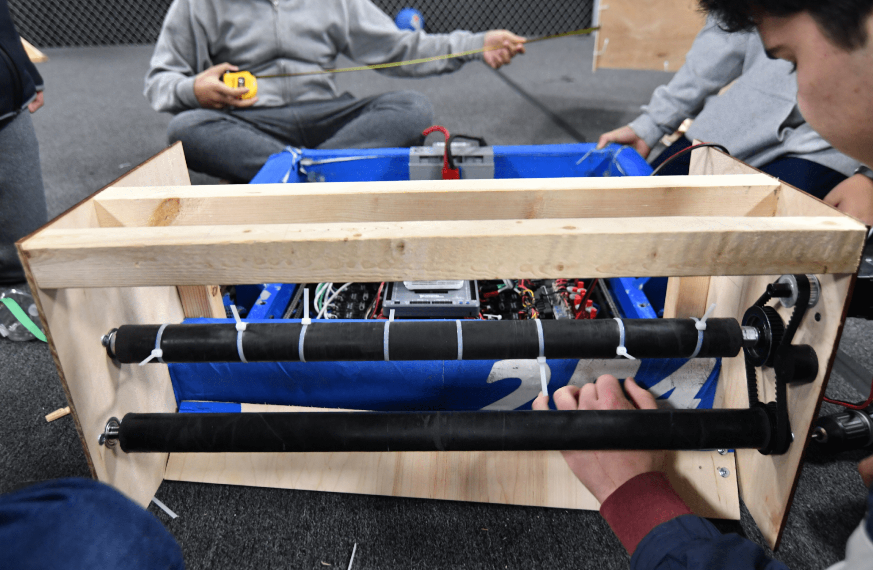
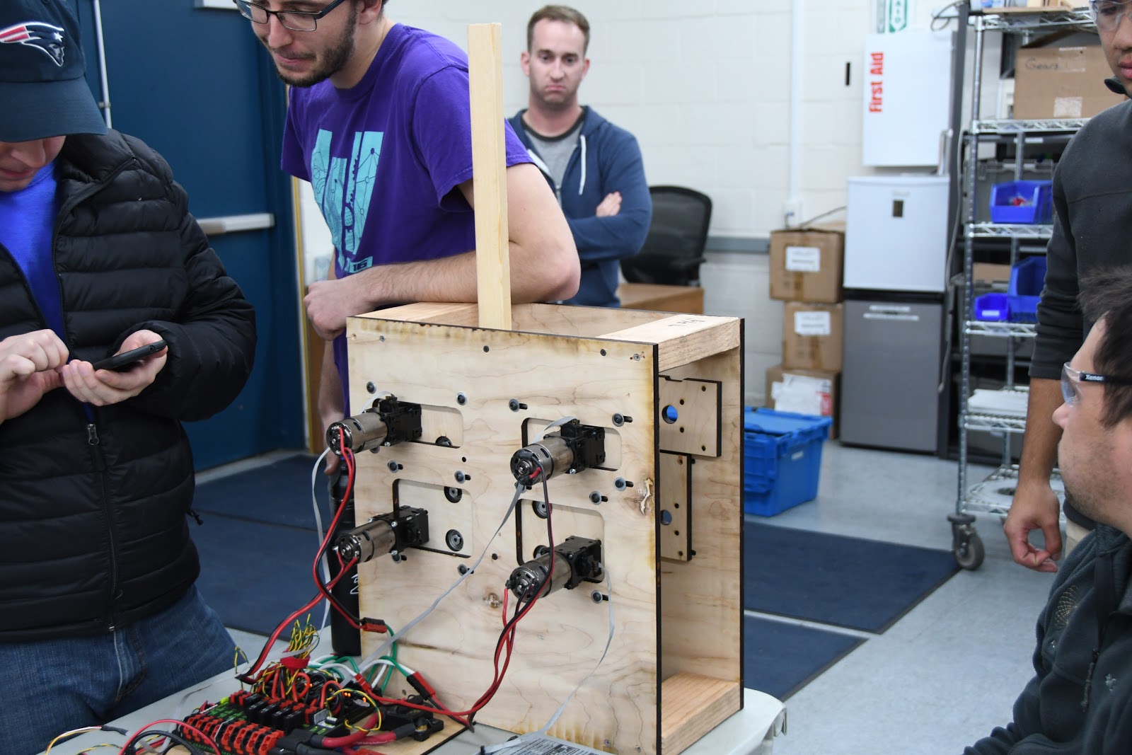
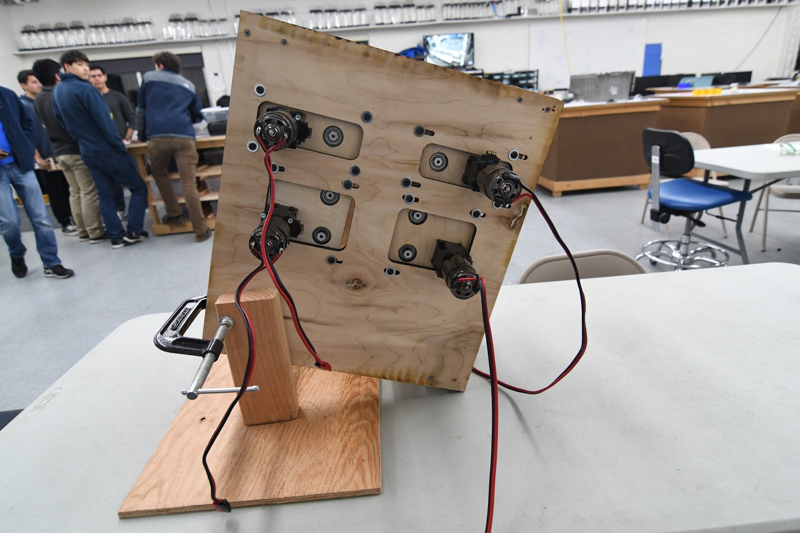
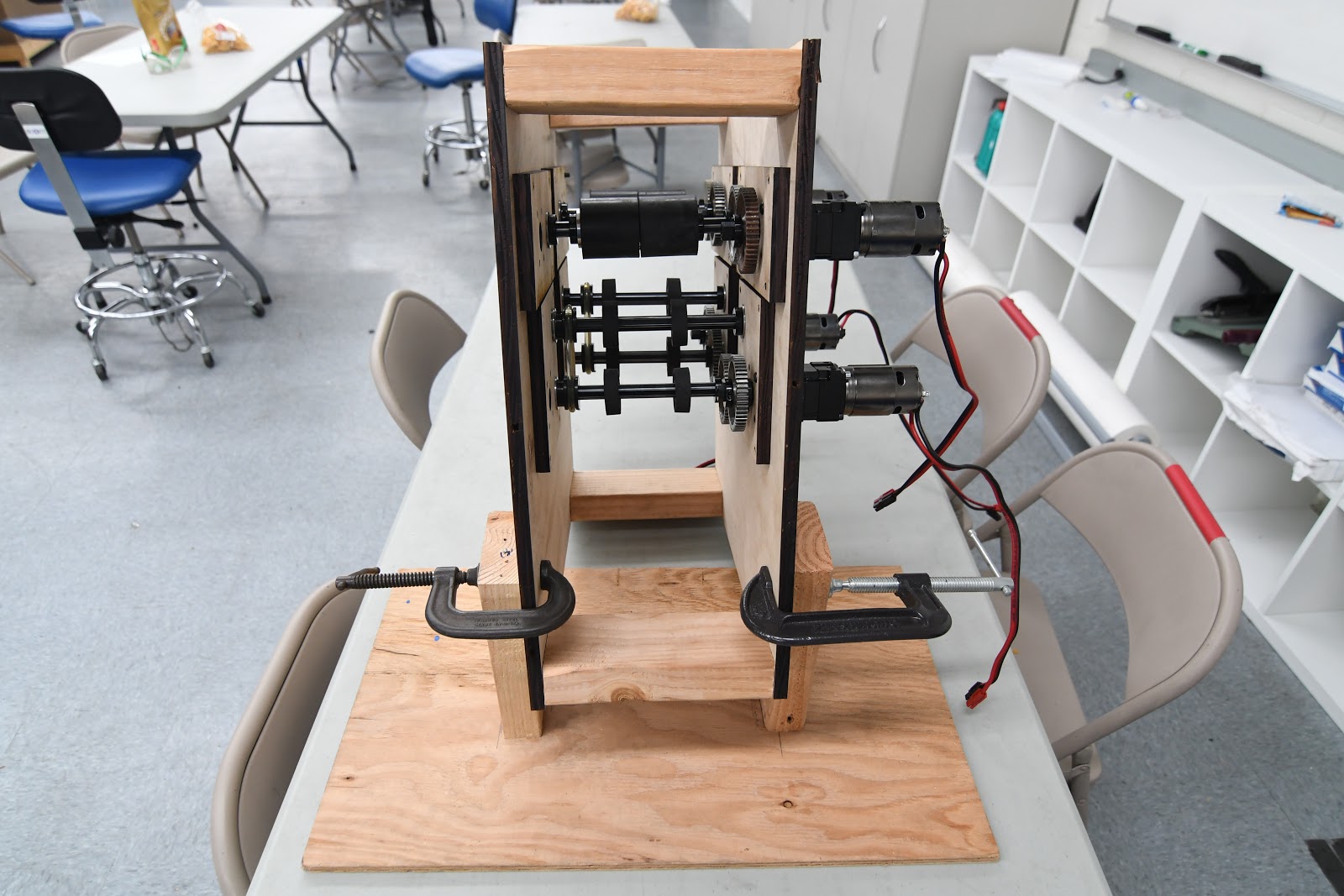
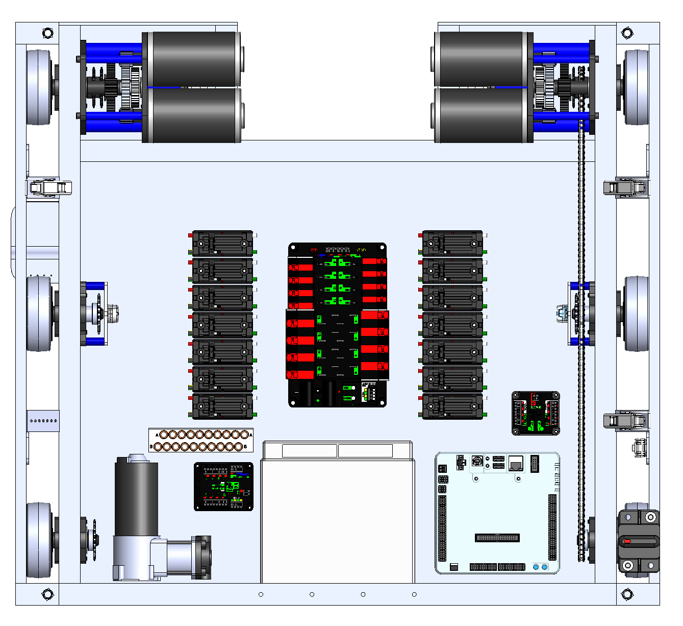
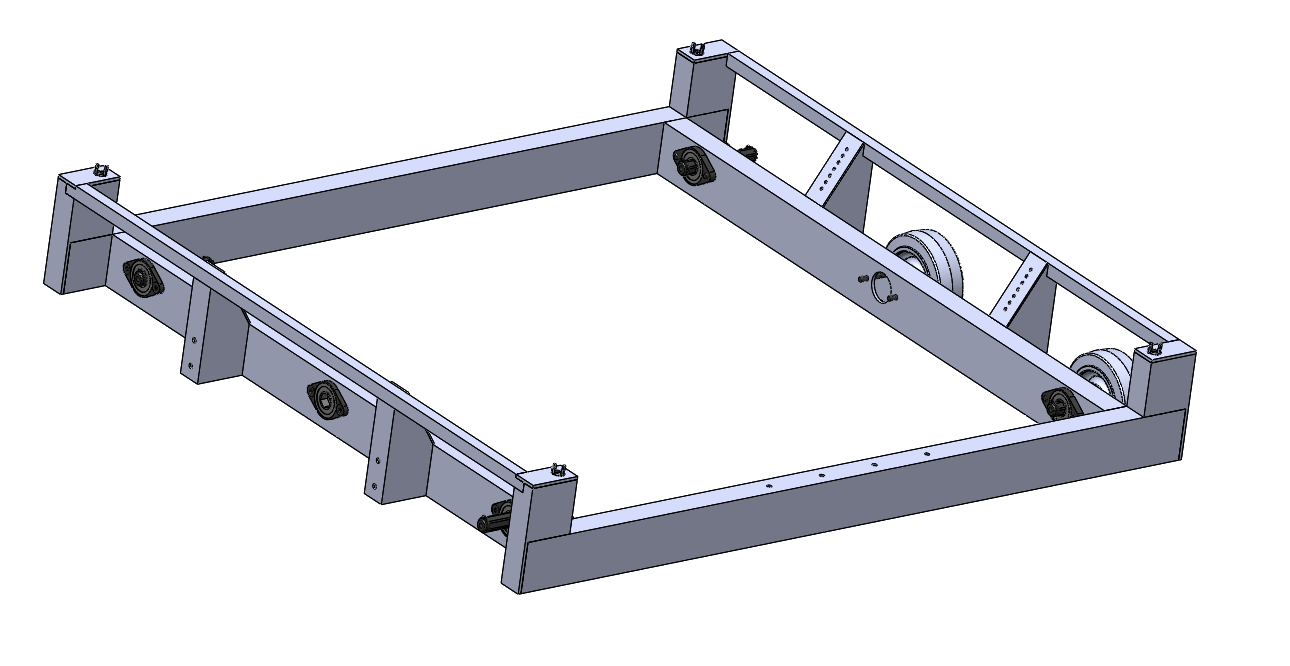
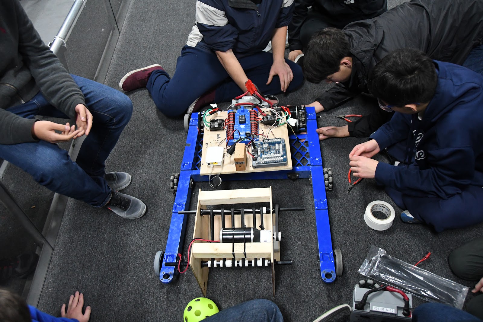
Wiring for Drivebase
Today we began wiring the drivebases. We have all of the Talon SRXs done and we have installed most of the components. We have a lot more work to do, and we will be working hard to get it done as soon as possible.
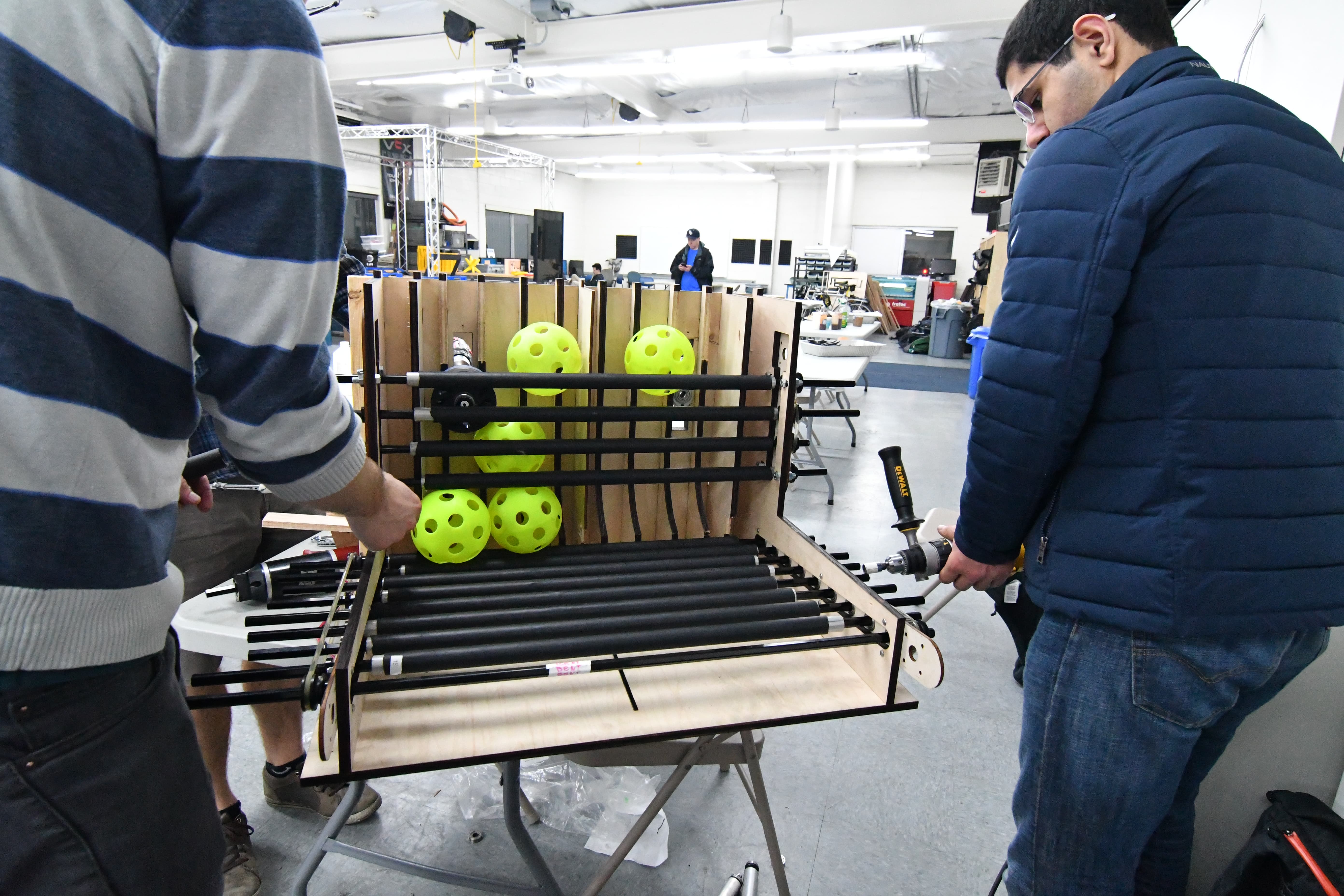
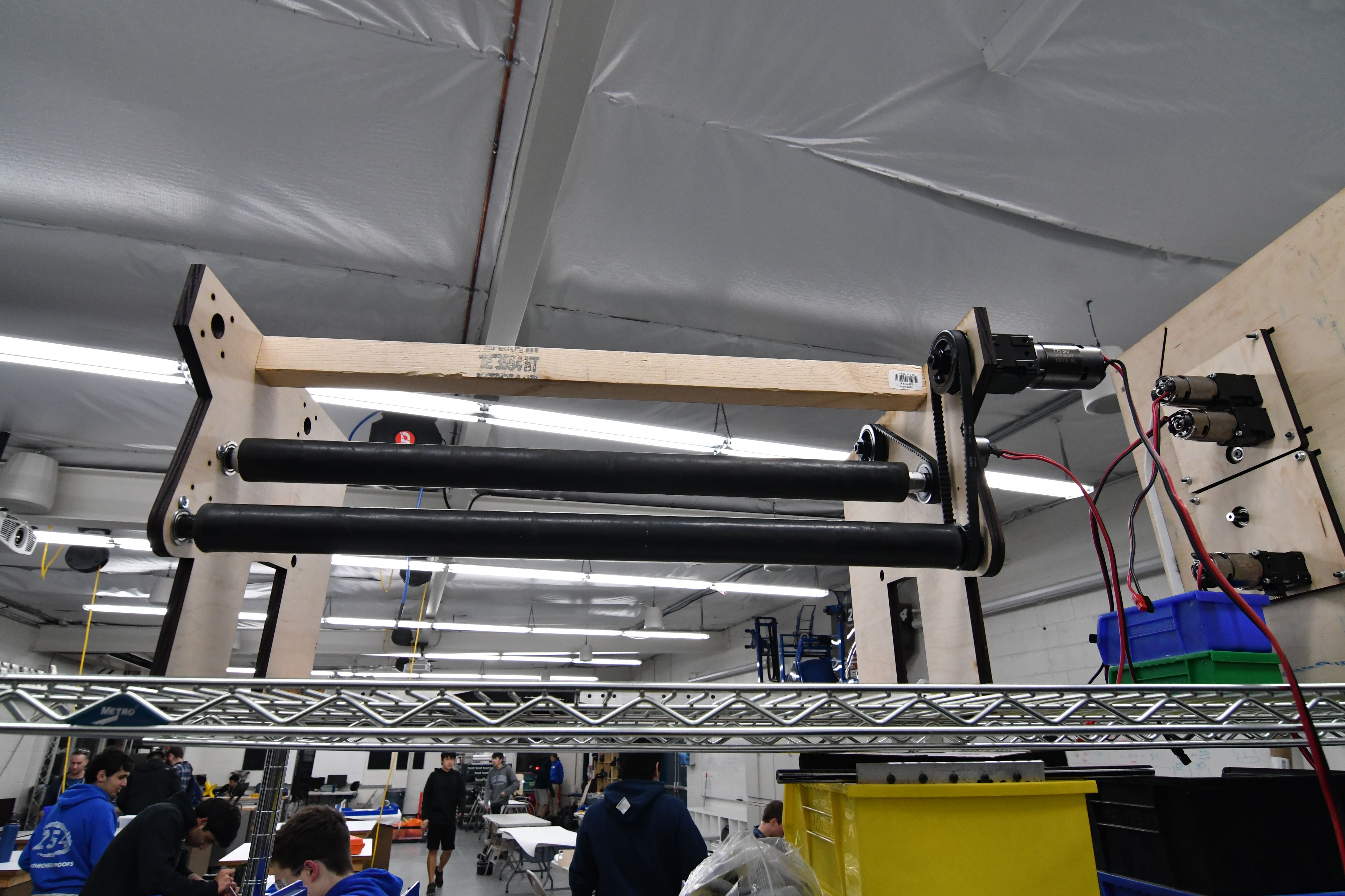
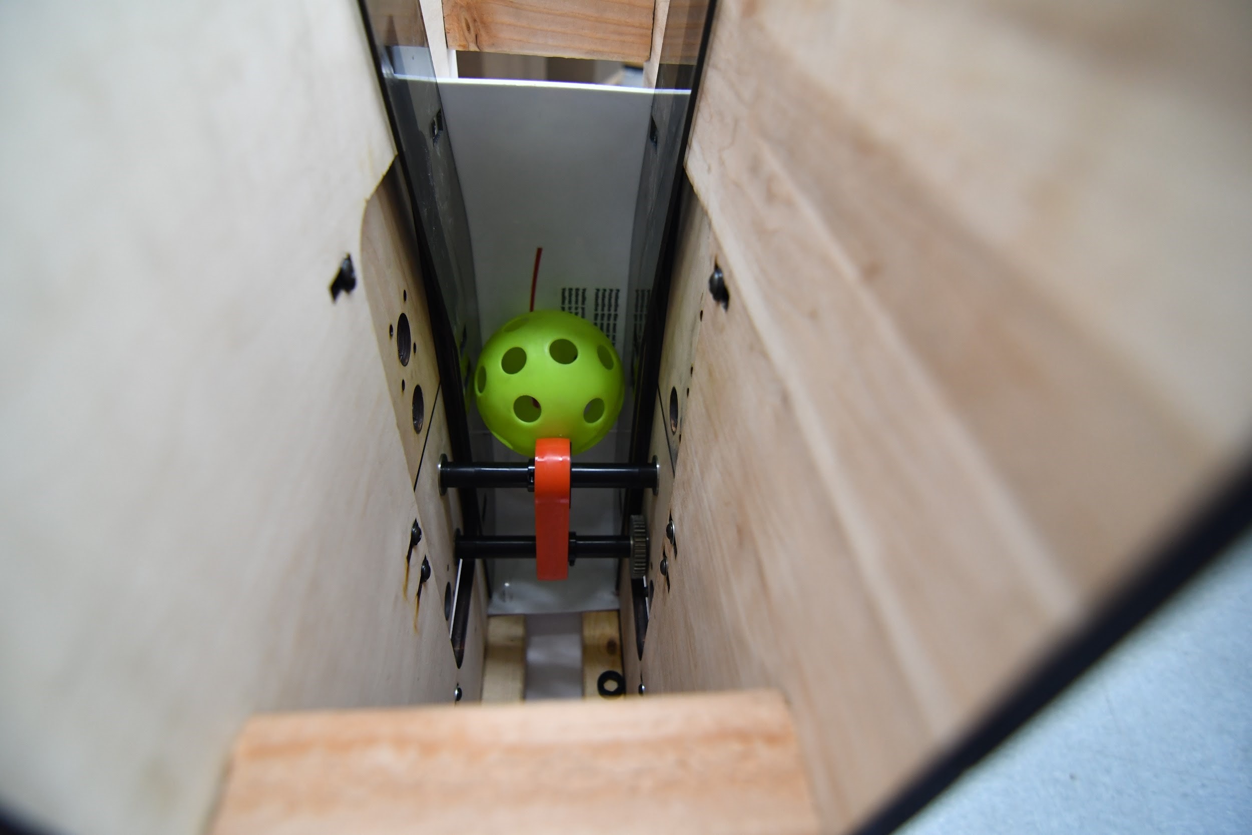
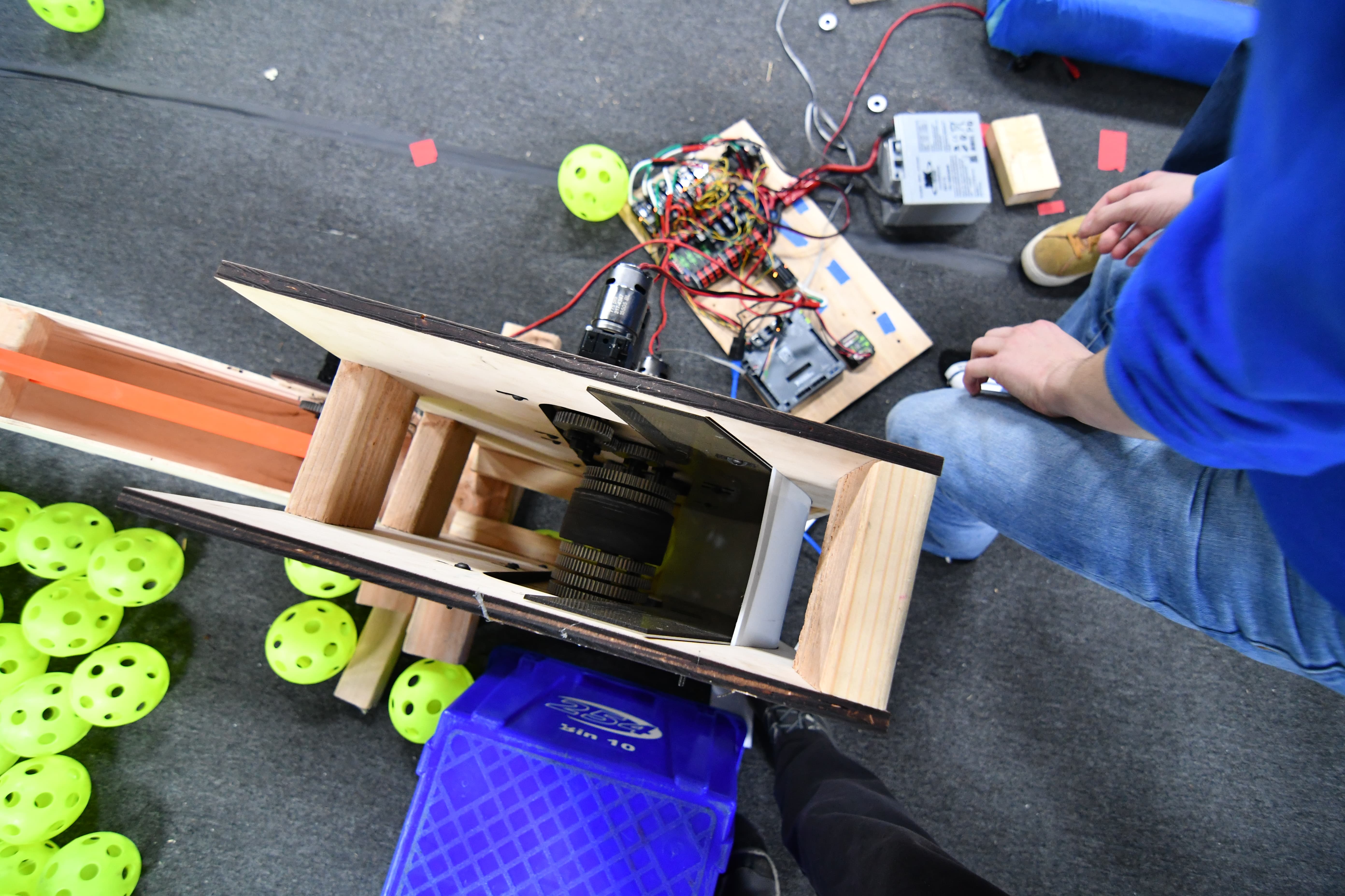
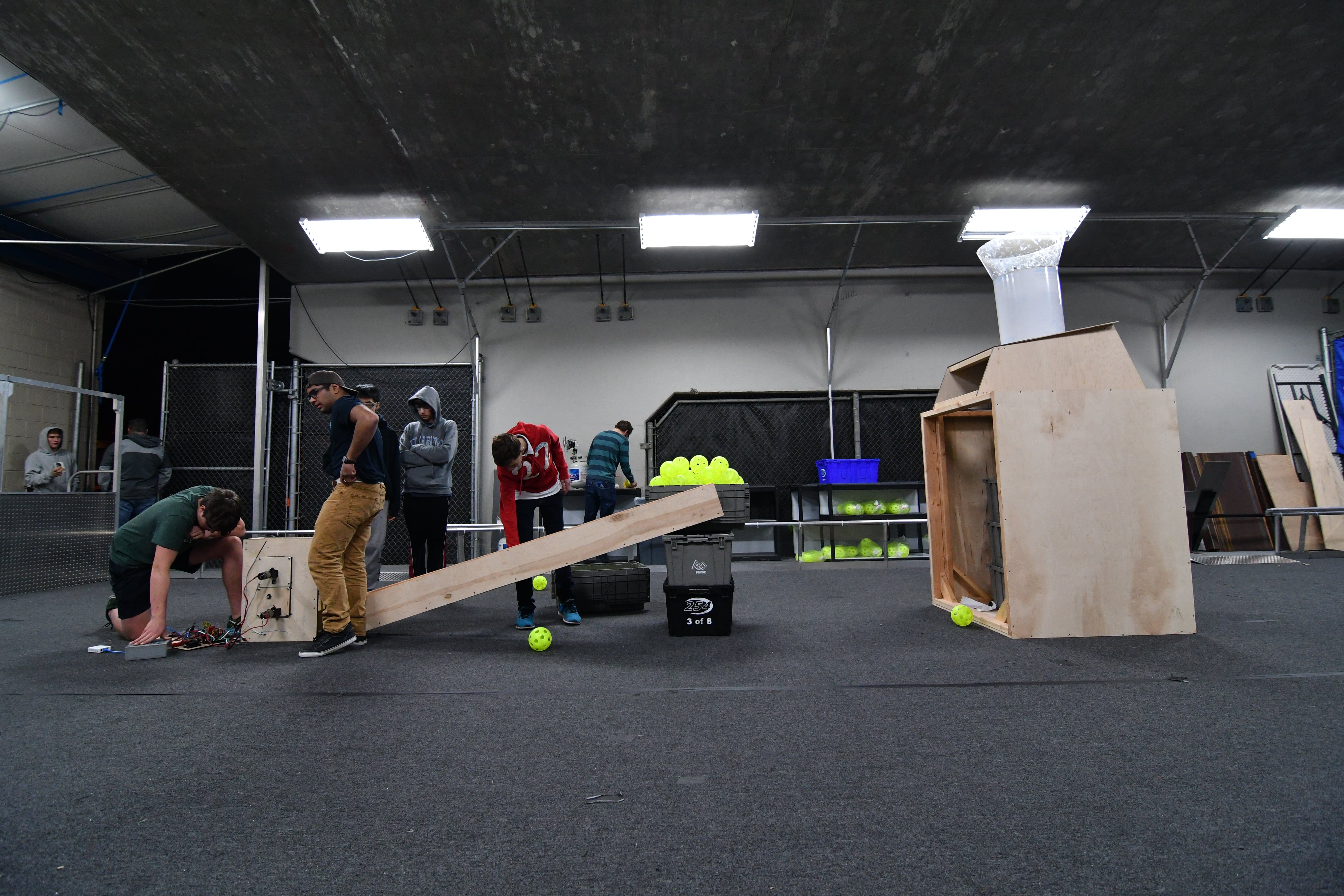
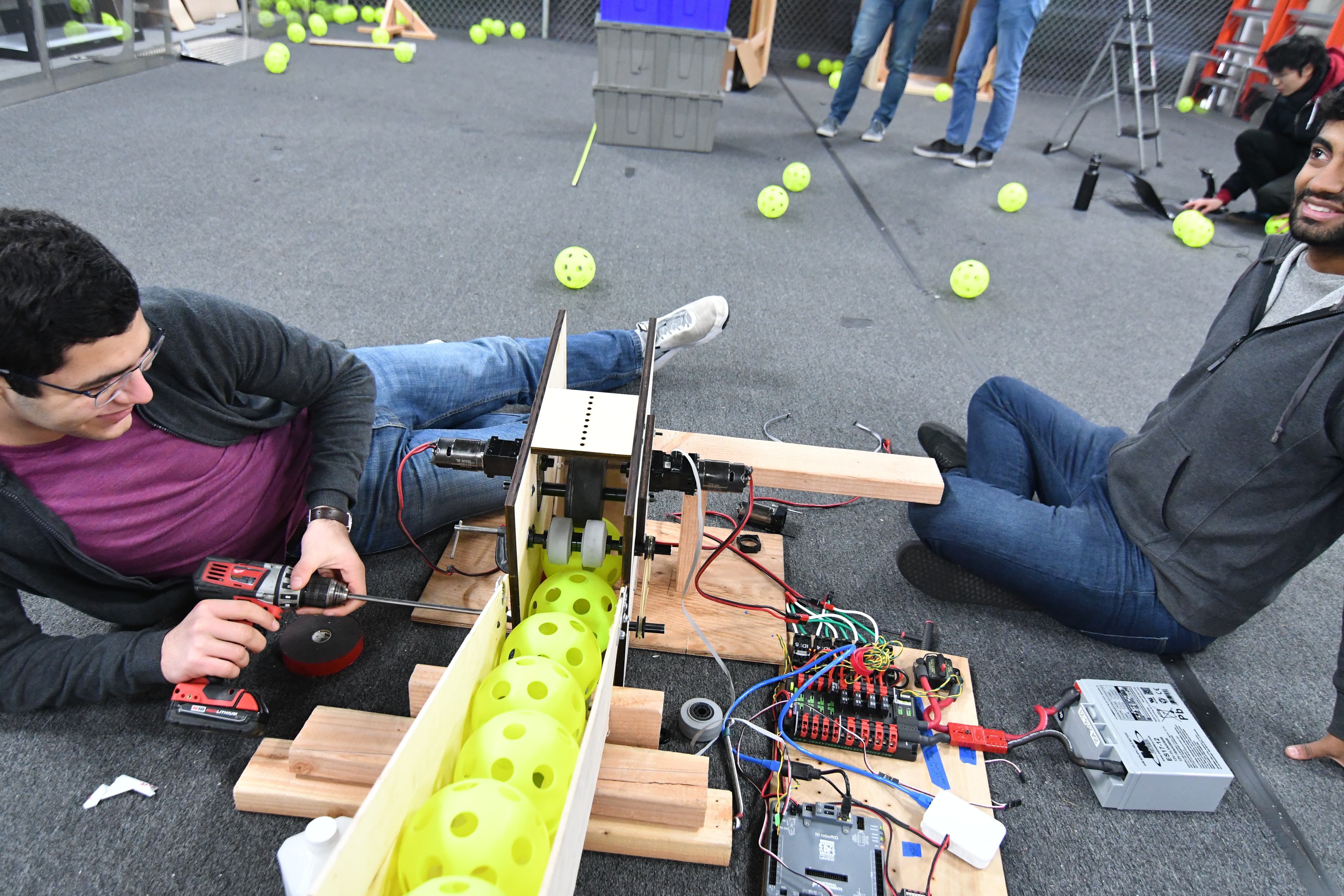
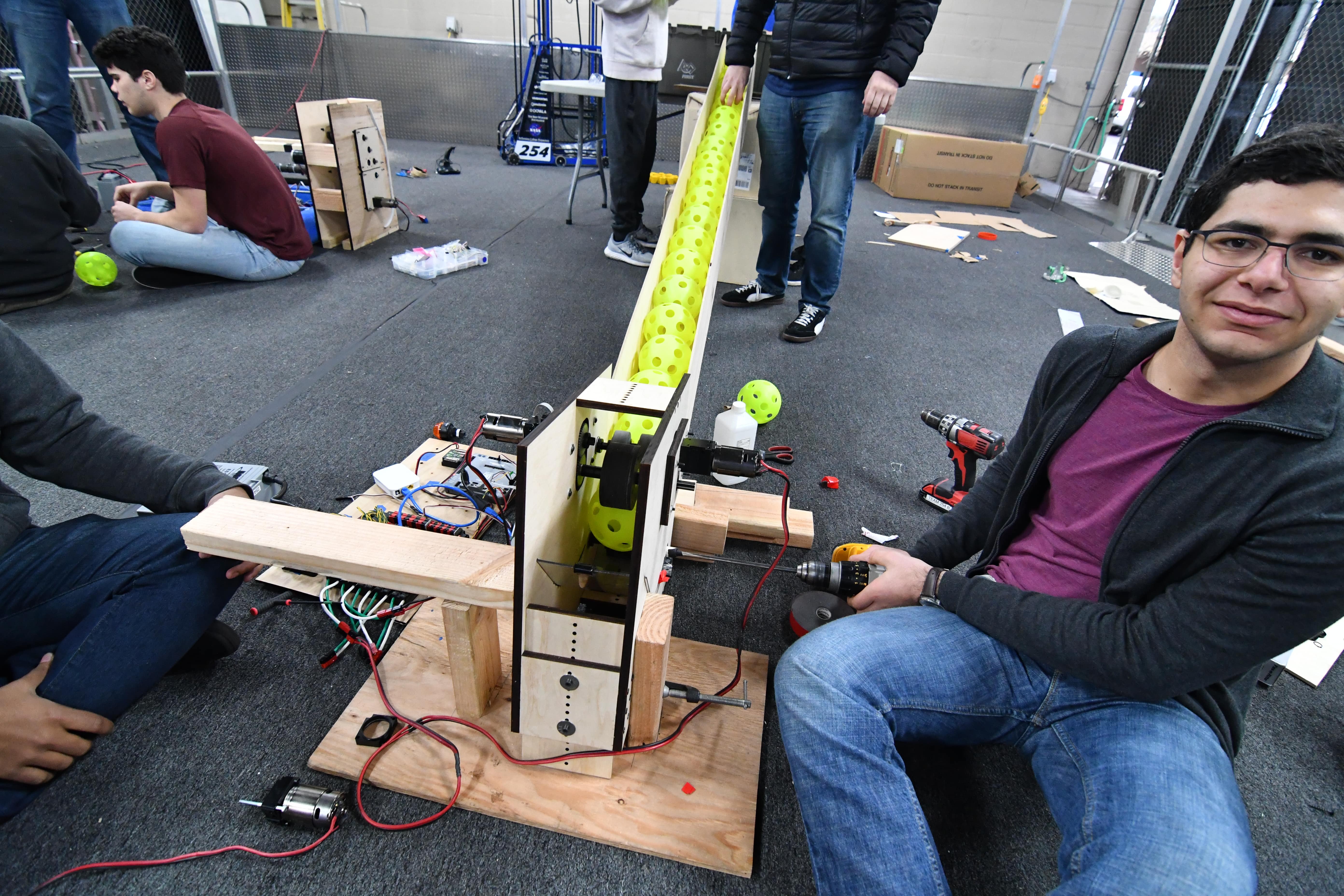
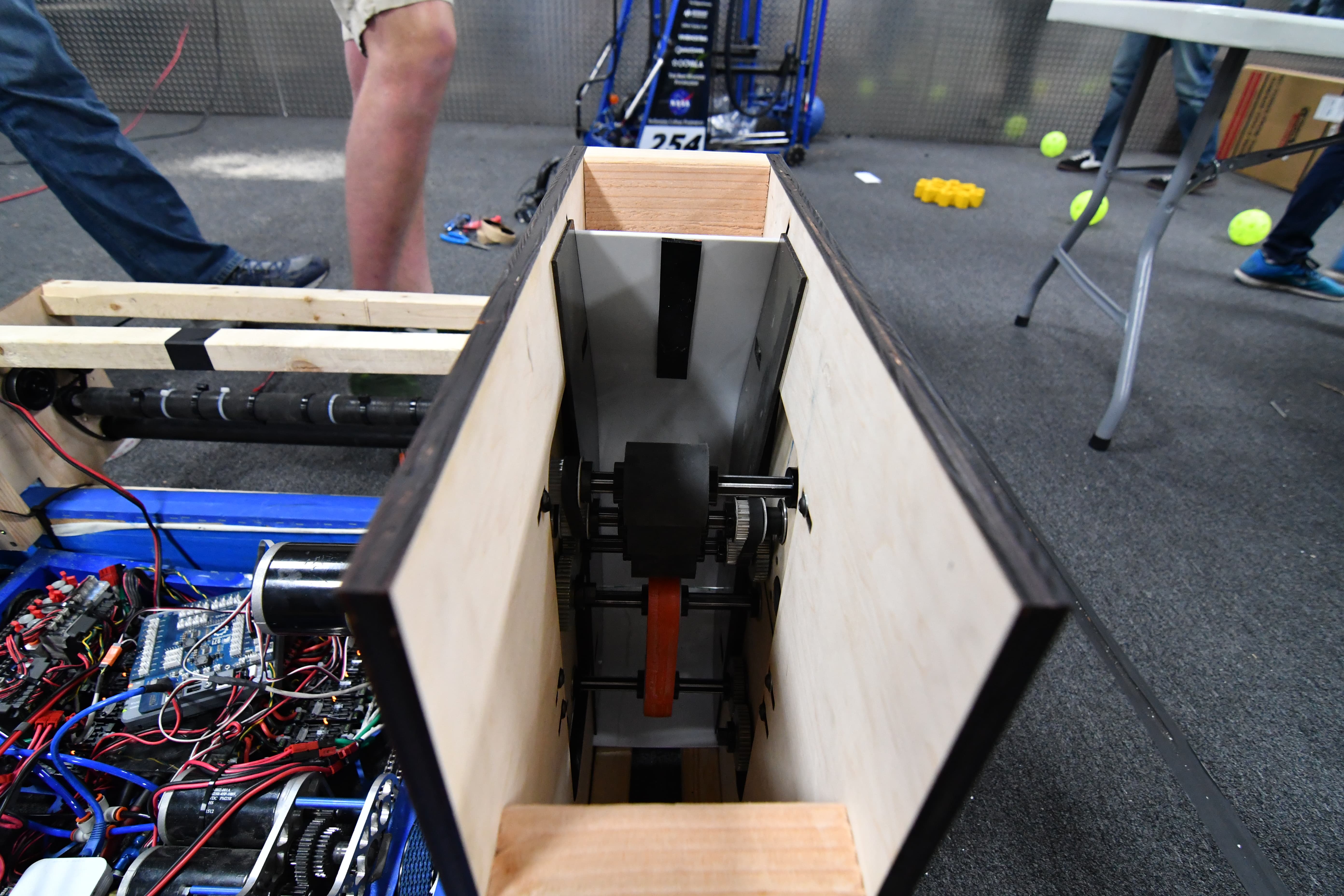
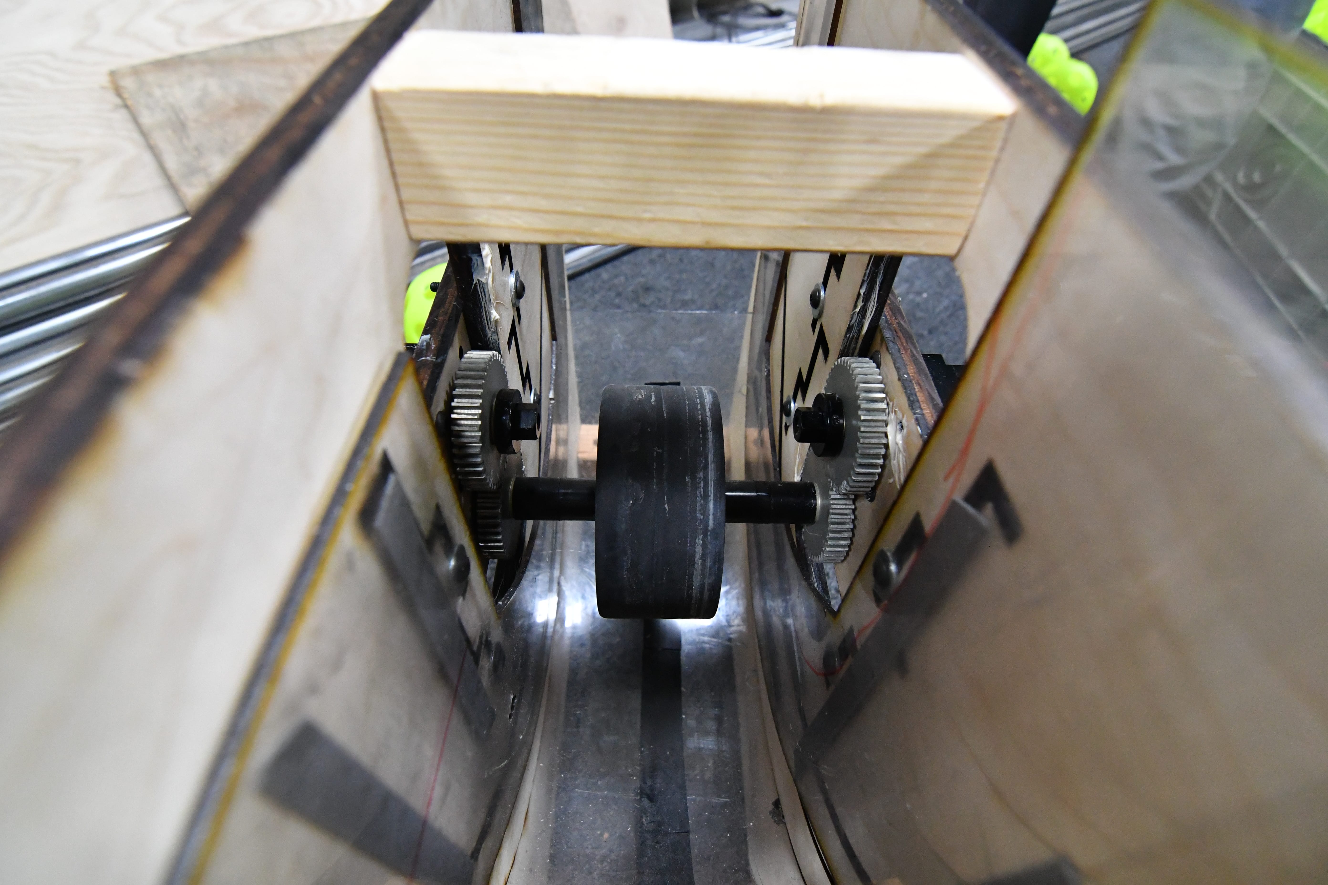
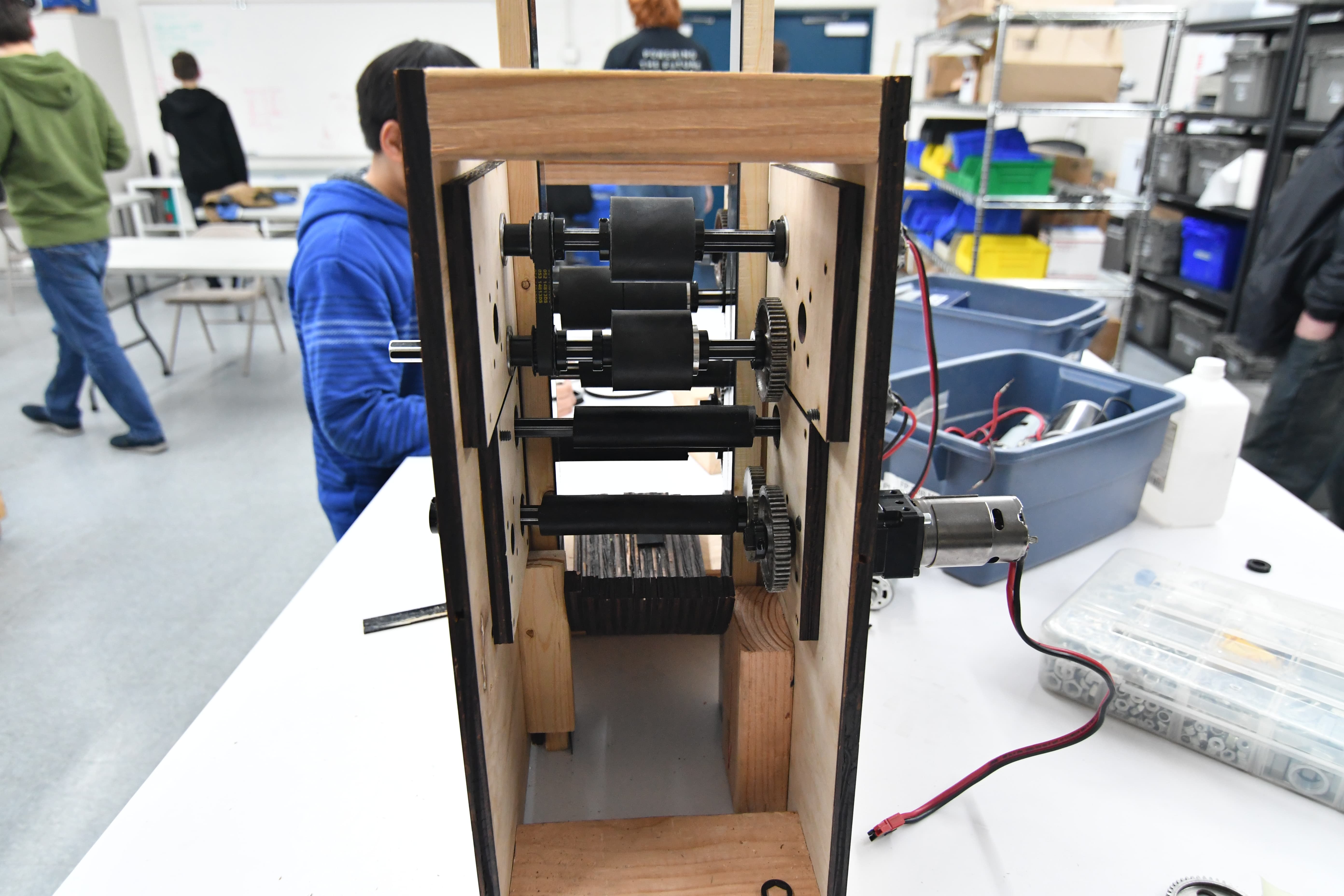
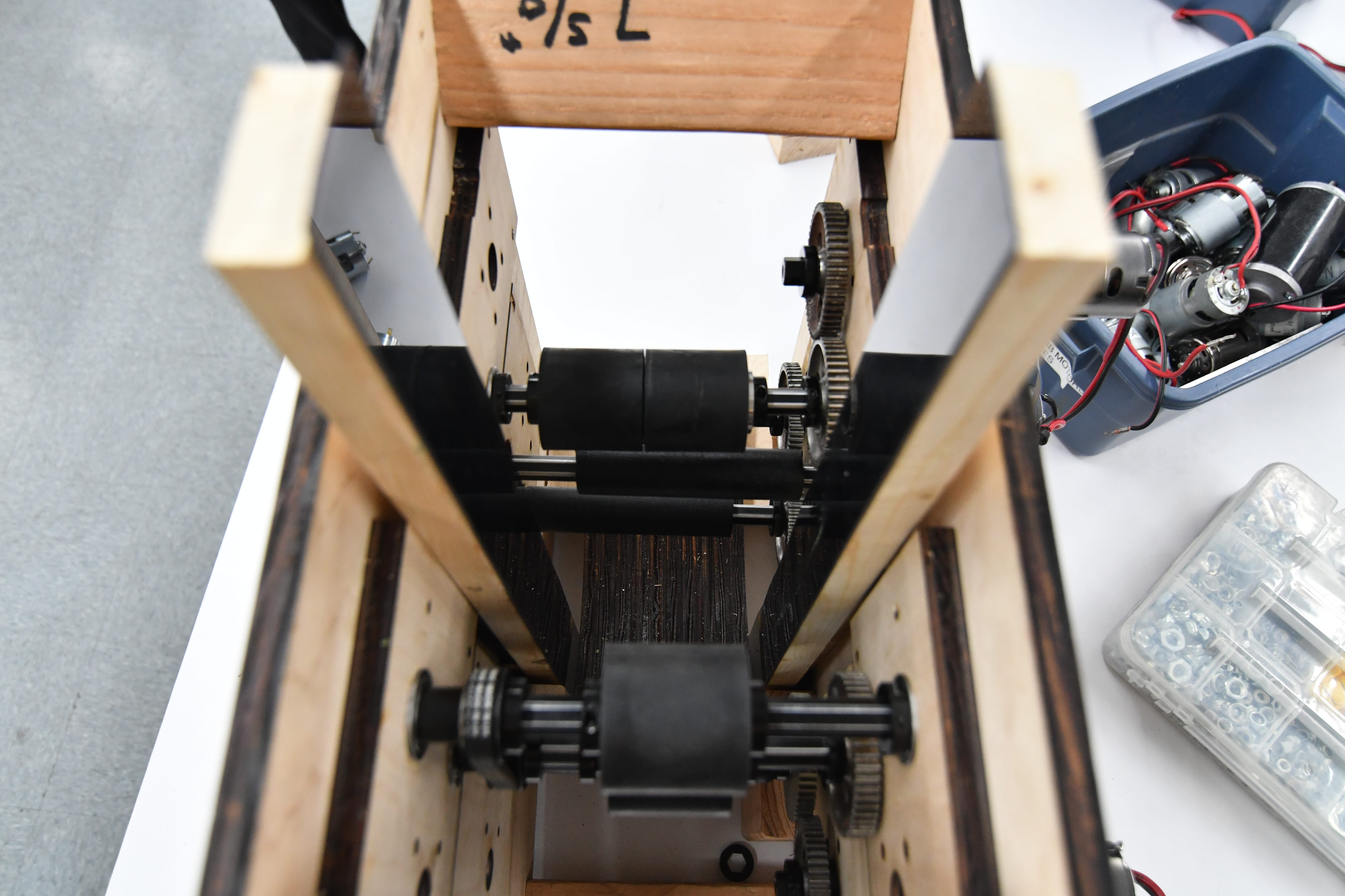
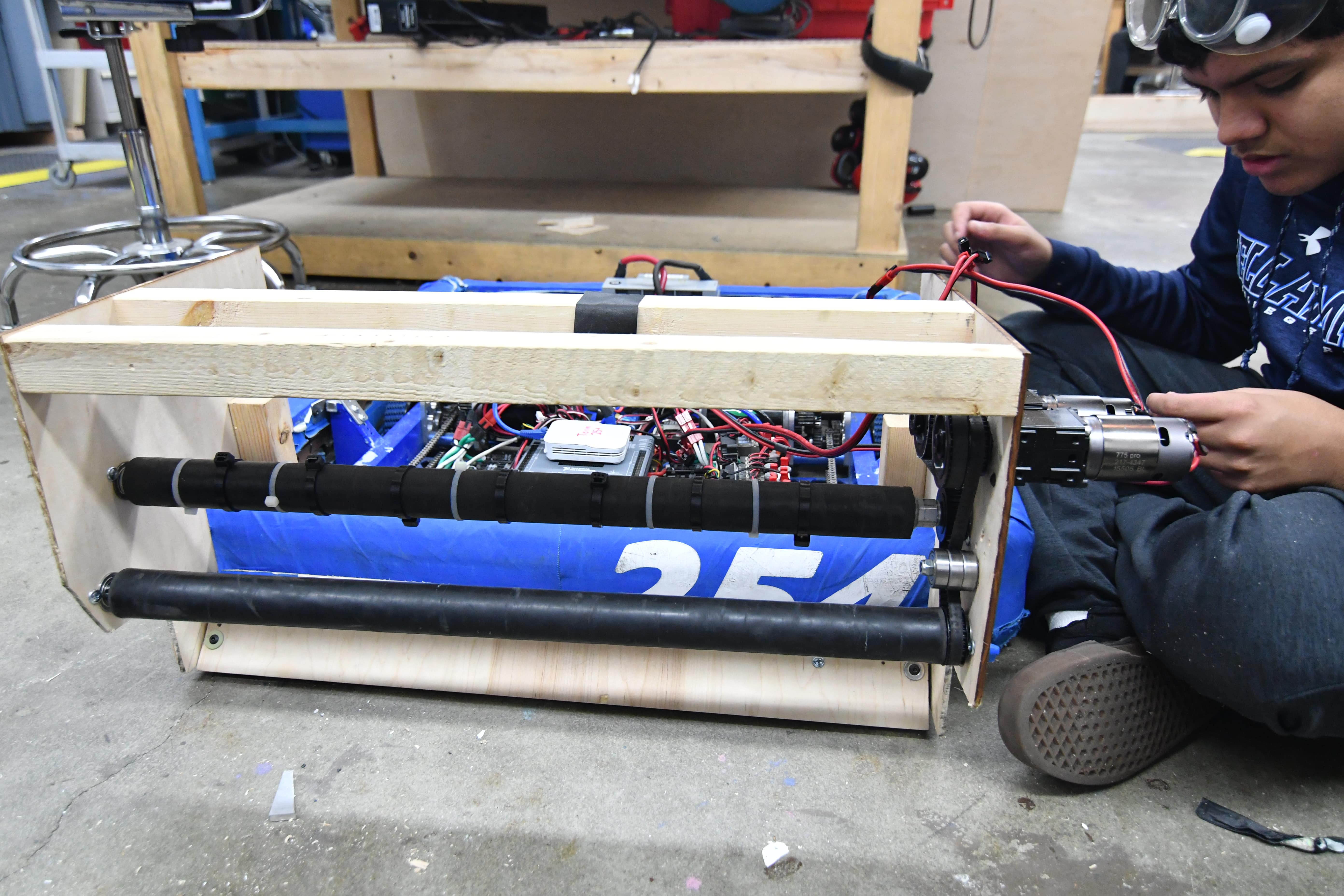
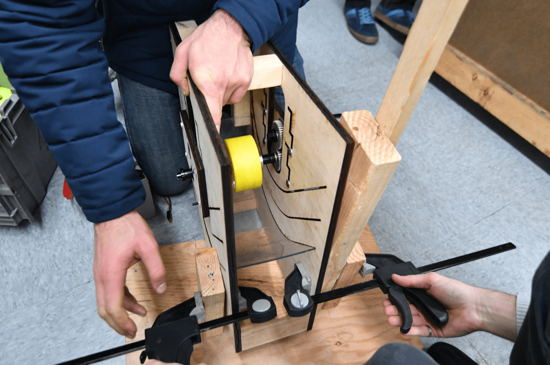
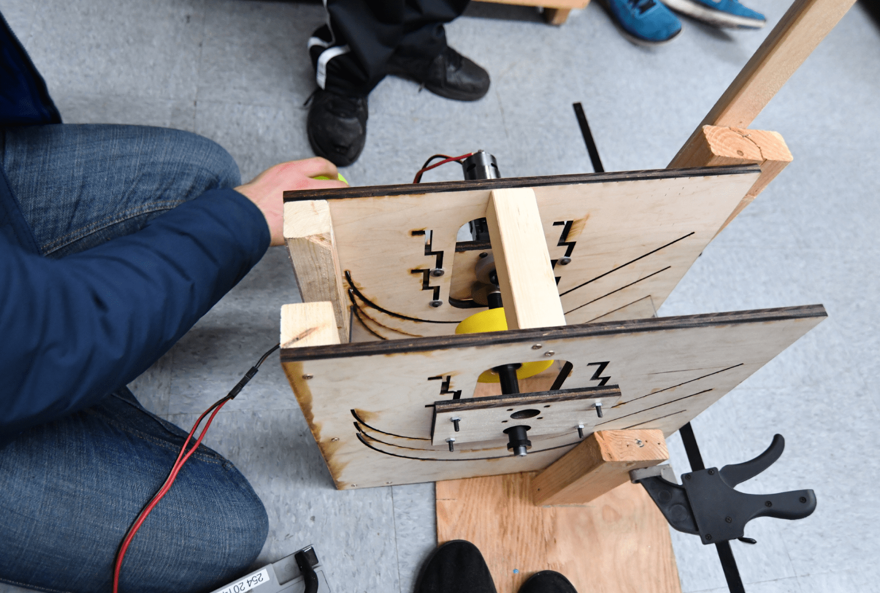
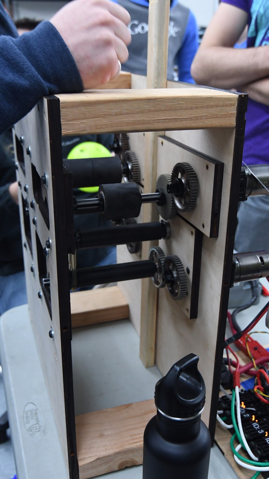
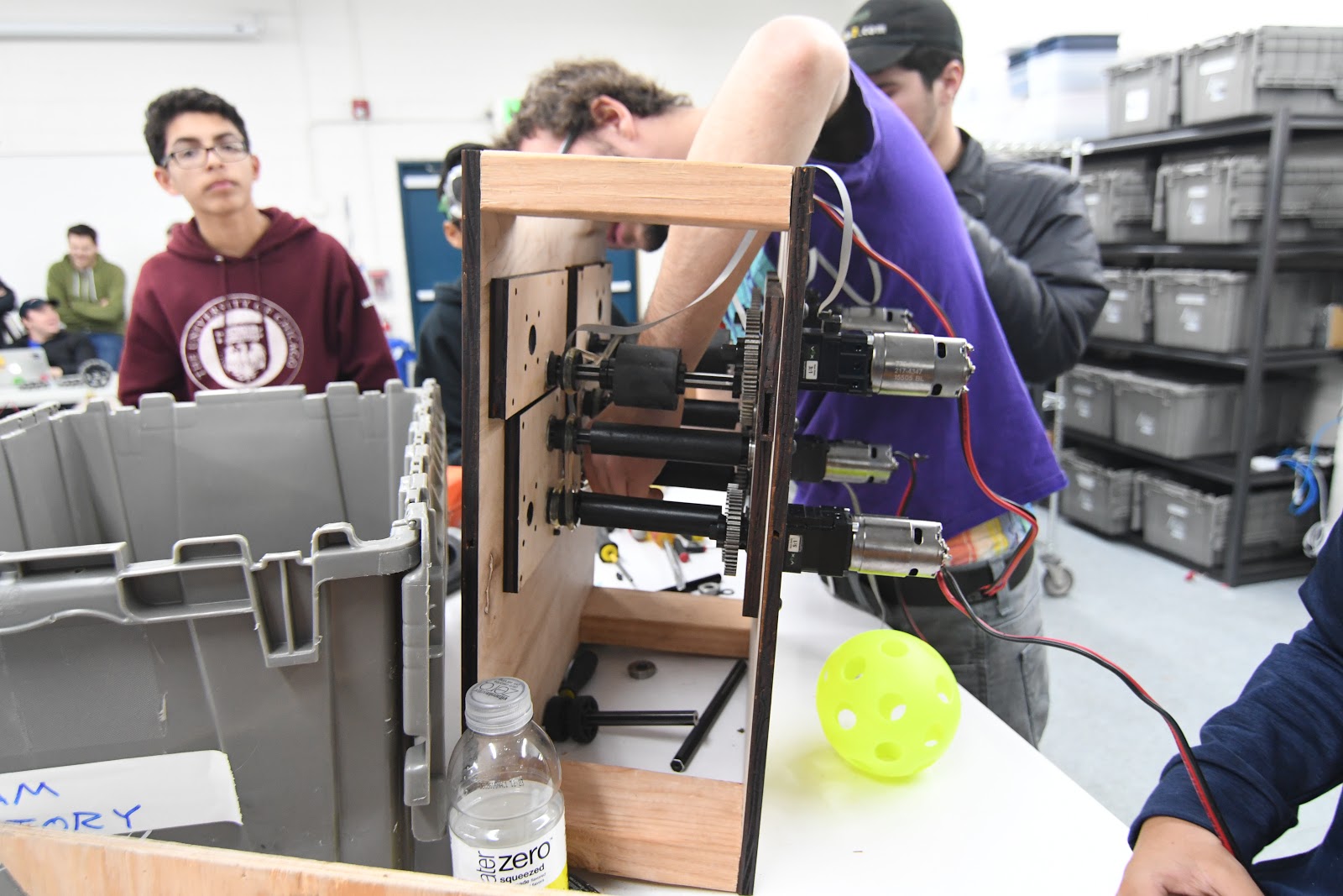
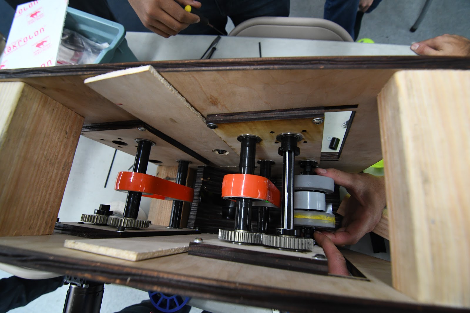
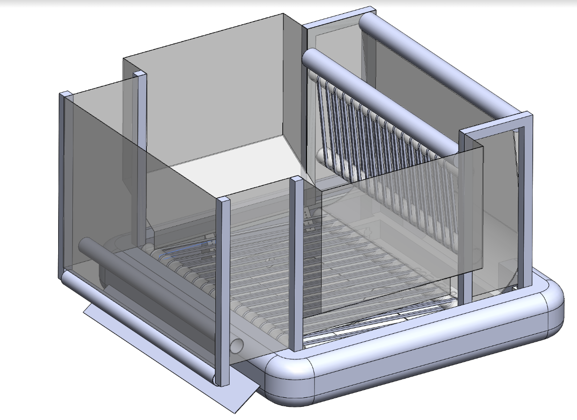
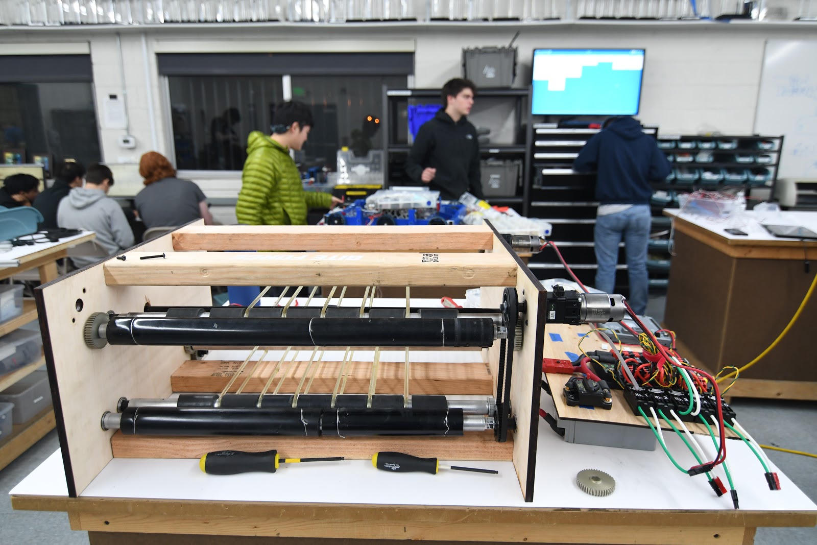
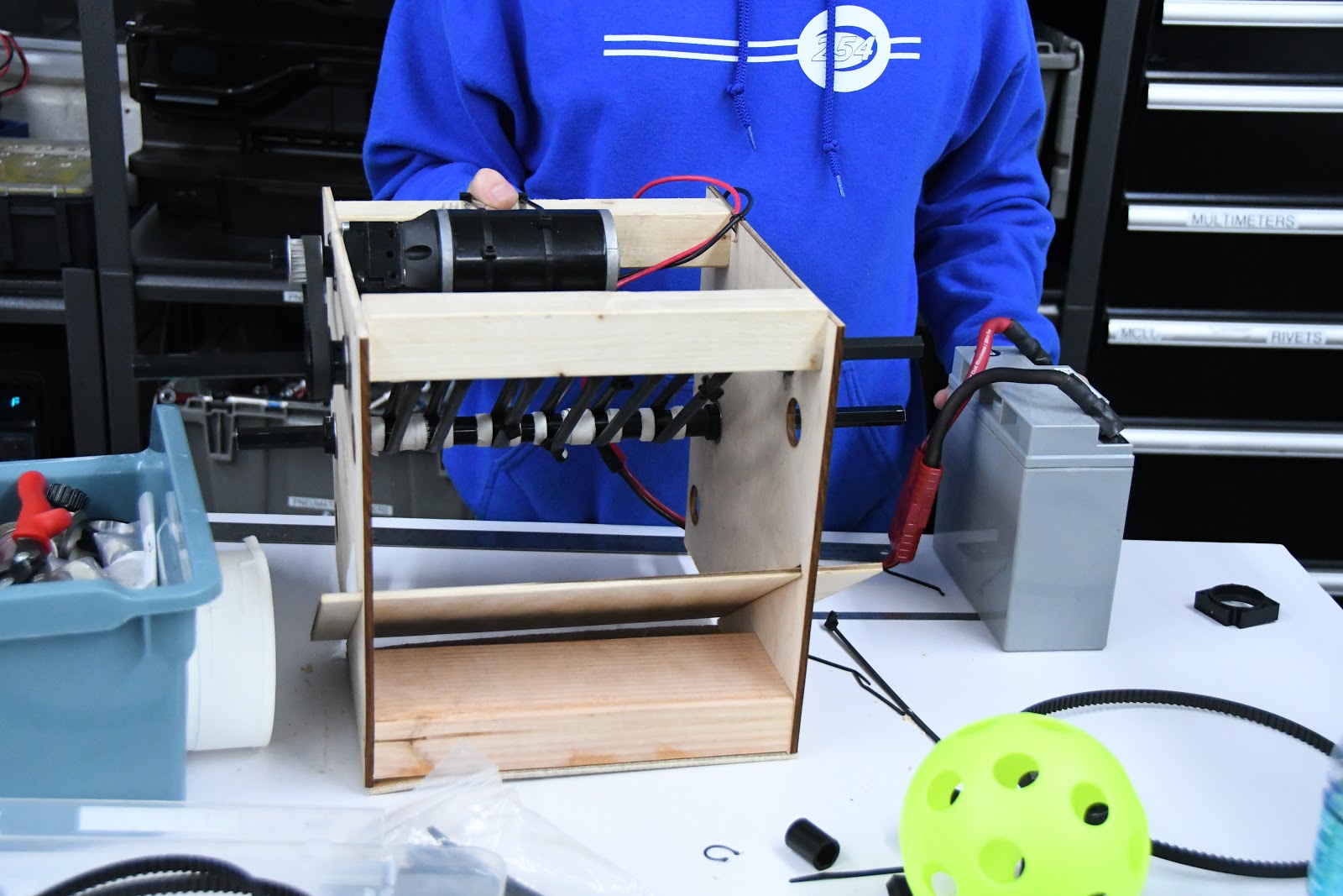
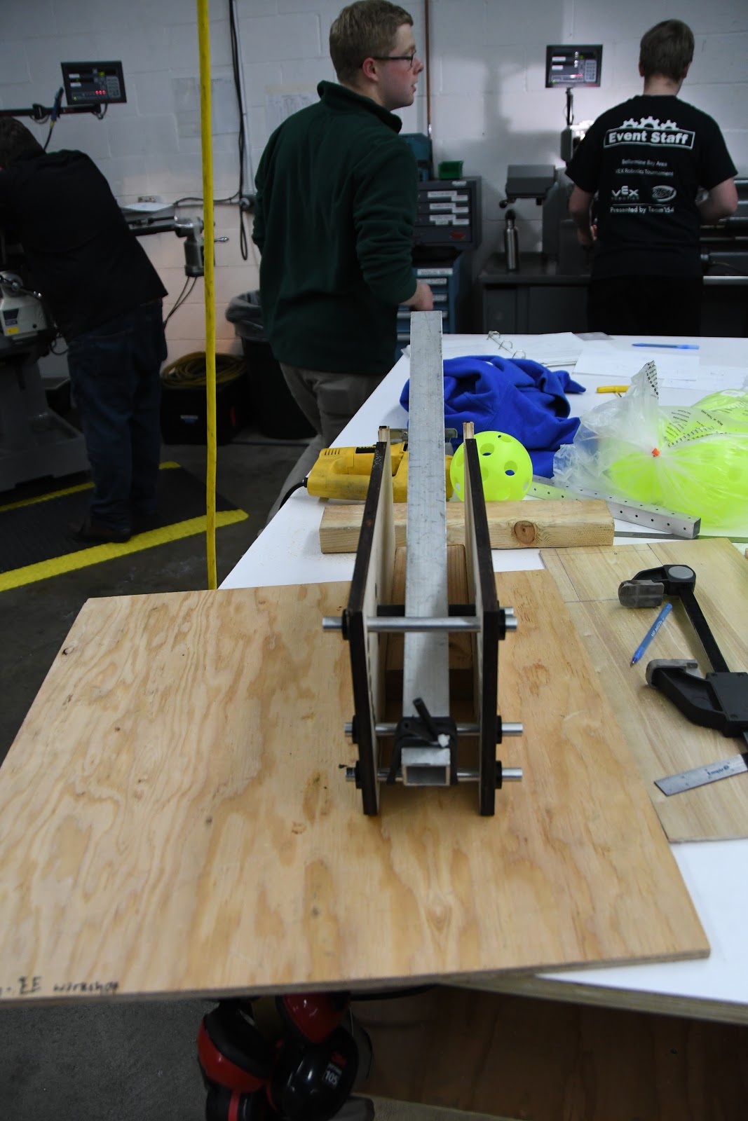
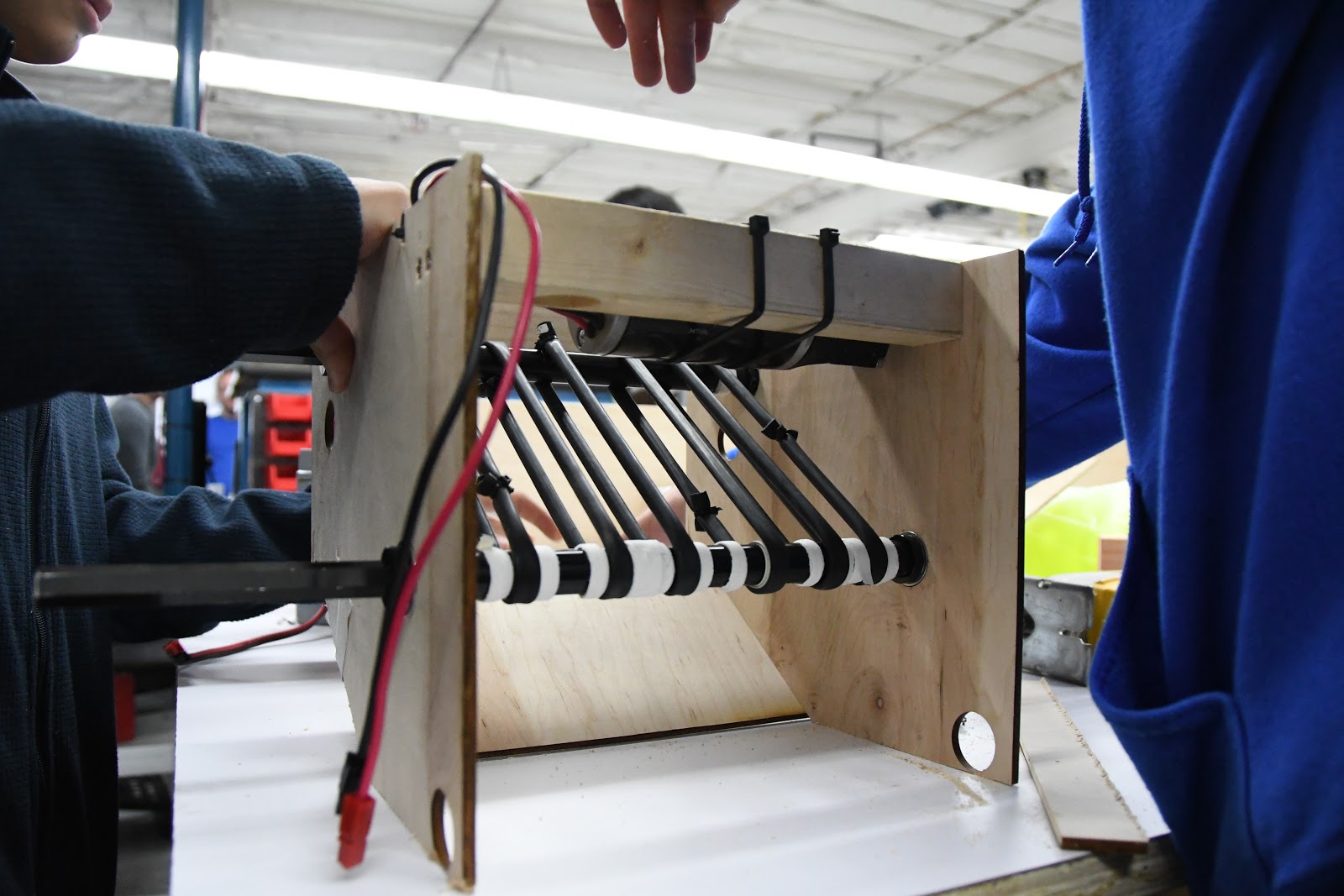
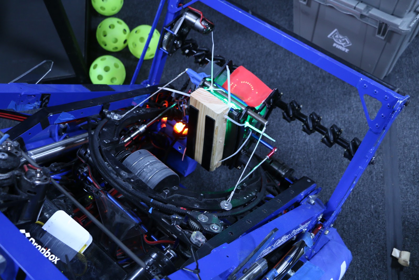
Zipper Hopper
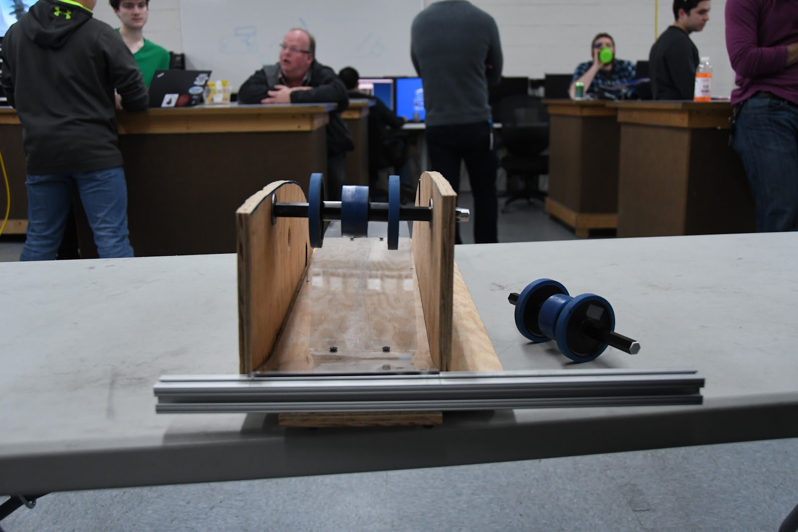
We worked on developing a new zipper hopper. We disassembled the old one, and built a new one with rollers. We built the rollers using aluminum tubes with a 7/8" OD and surgical tubing around them. The hubs are VEX Pro 1/2" hex spacers malleted into the shafts. We beveled the shafts so that the 'plugs' would be as colinear as possible when stuffed into the shafts. We also ran the floor and feeder with polycord rollers. We quickly discovered that after running it for a short period of time, the polycord would break or just slip. We also found that at high RPMs, the amount of friction caused so much heat that the polycord pulleys we were using melted. We then had to transition to belts and pulleys, which fixed some of our problems. After our testing, we found that the rollers would "hot-dog" and sometimes not feed the balls. While it was better than the polycord, it still was not good.
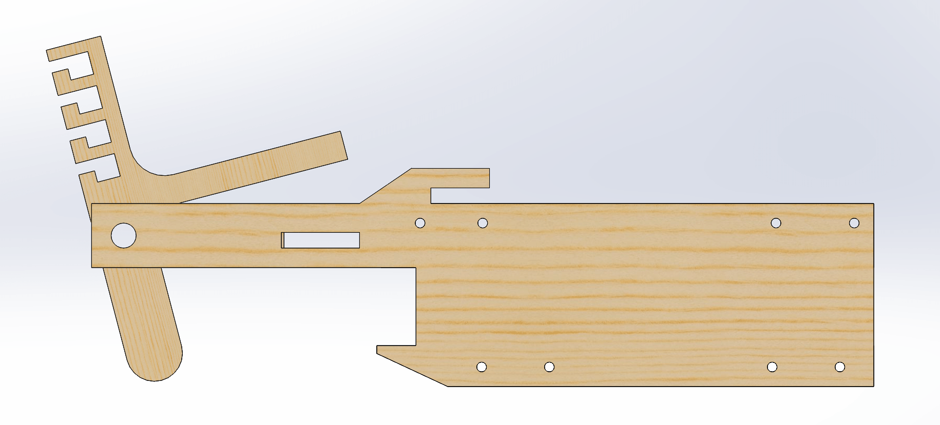
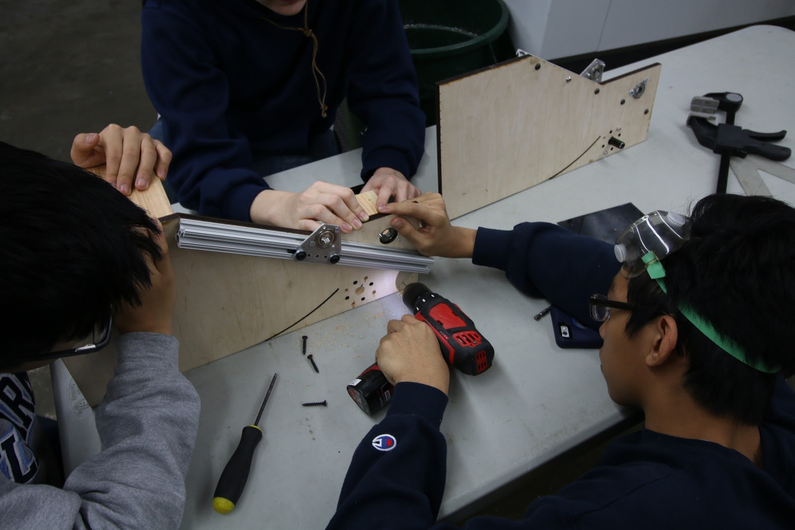
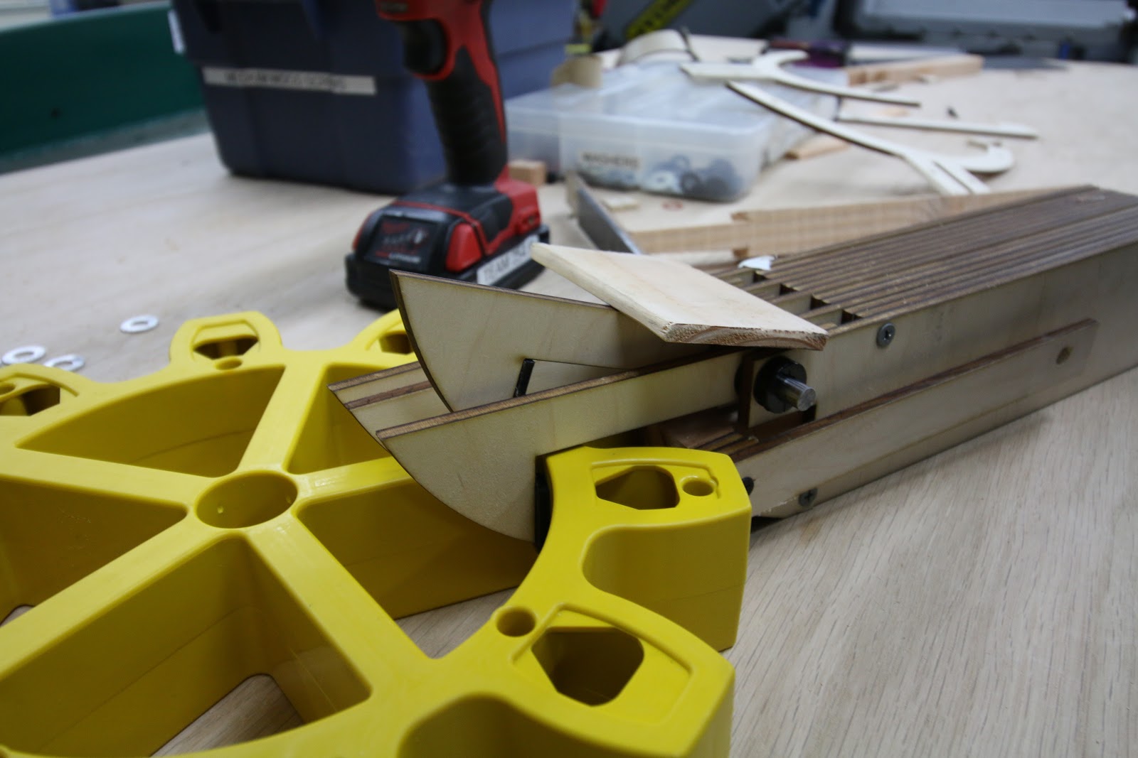
Intake
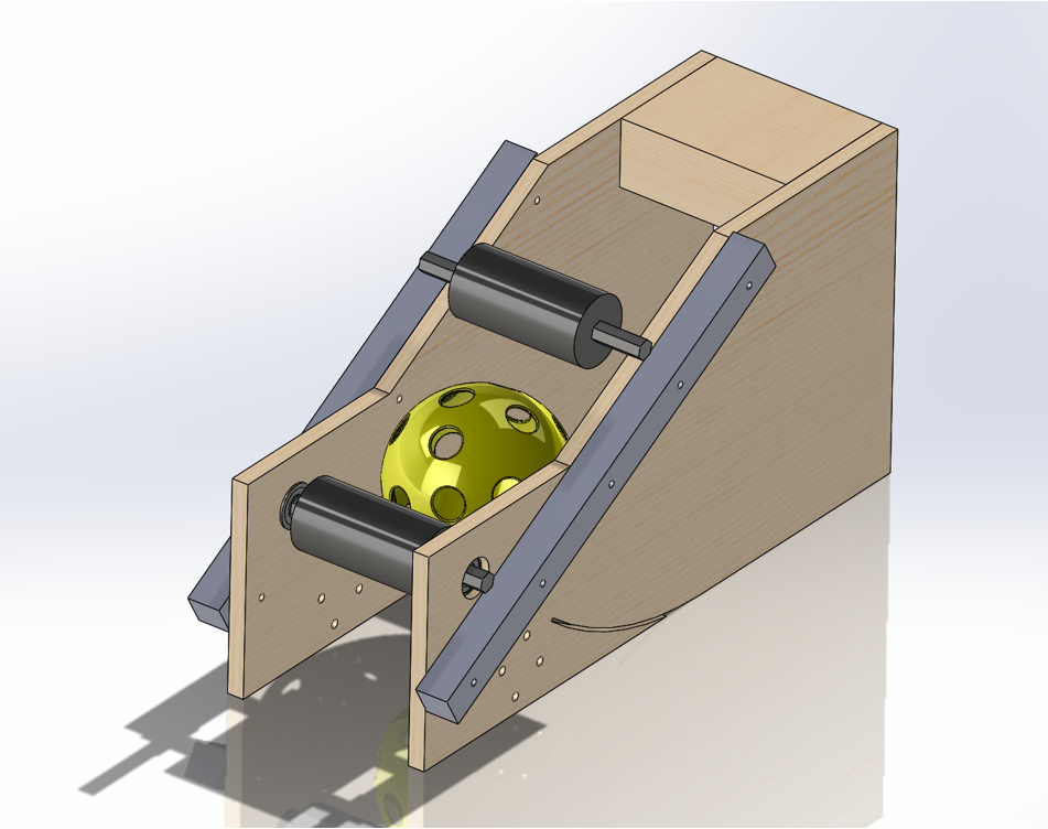
Today the intake was remade and retested to finalize geometry before it's fabricated out of metal, and we found that the design maintained a good amount of compression on the balls throughout. We did not get a chance to fully test it yet due to some mistakes in the prototype that led to it being remade once more, but it is almost ready to go for thorough testing tomorrow.
Programming
Camera Calibration
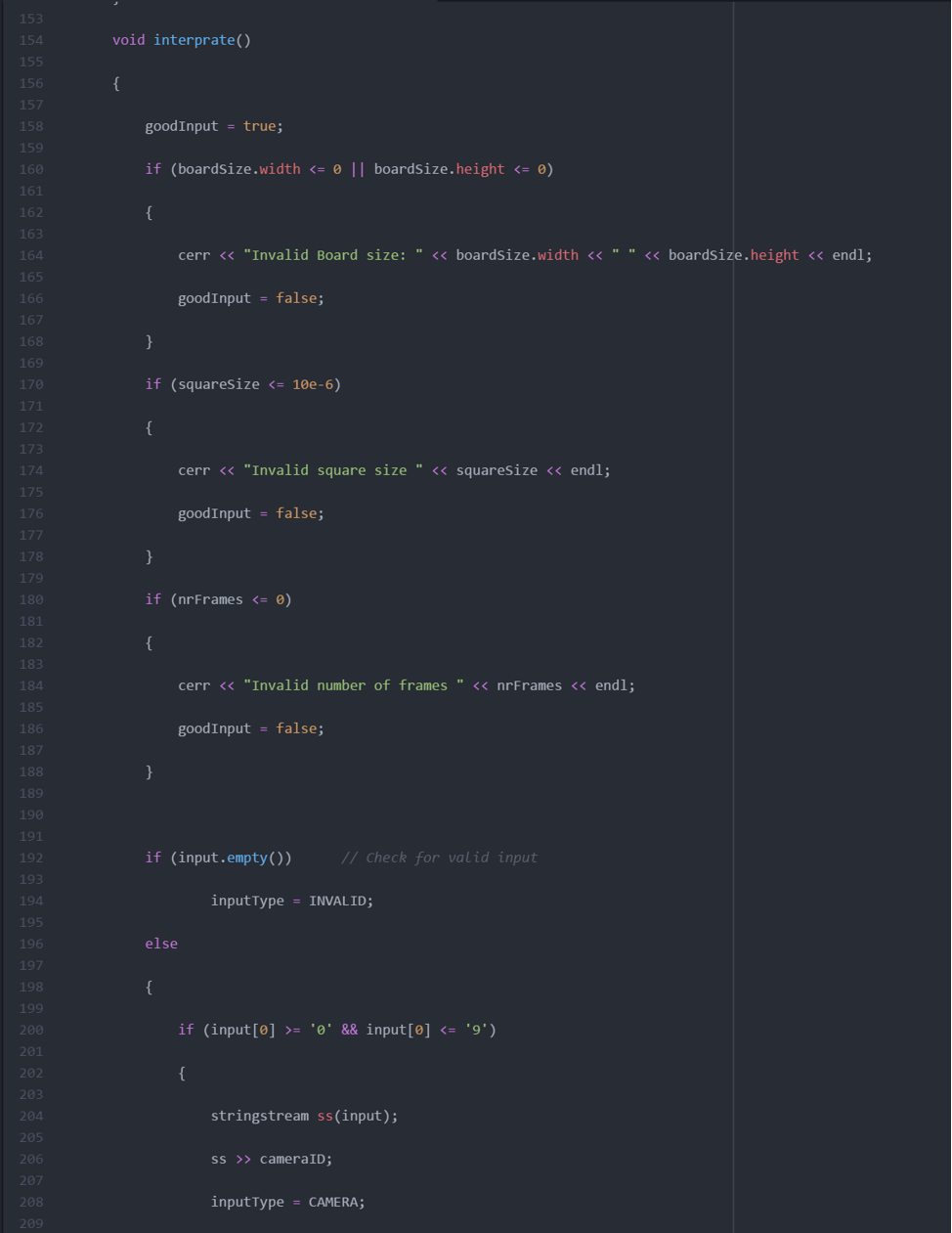
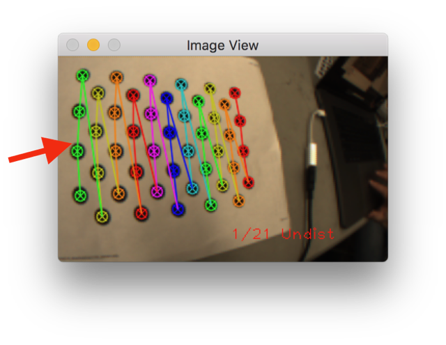
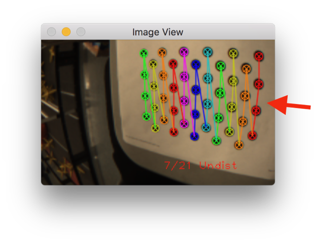
Today, we calibrated all six Pixy cameras. We altered our code, so depending on which camera we are using, the code reads the camera matrix specific to that number Pixy. We saved all of these in .txt files in a new folder called resources. The next step is to add this folder to the JAR file (Java ARchive) so that it is deployed onto the robot. Currently, the fps (frames per seconds) in which the calibration program is running at is really low. We sped it up, but that crashed the program, and the calibration wasn’t as good, so we changed it back. We also had some trouble with Pixy #4. There was a black splotch in the top left corner of the image. After unscrewing the lens, we found a speck of dust that we blew away using compressed air from the pneumatic hose. This fixed the camera. Under FRC-2017/camera-calibration/ there is a file titled README.md which contains instructions for calibrating the cameras.
Here is a sample applet which shows how we take an image (shown on the left) and undistort it (shown on the right).
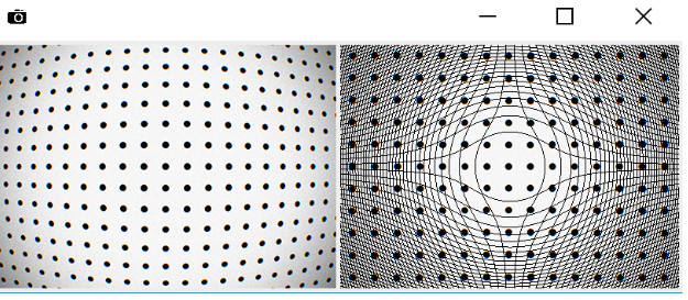
As you can see, the dot grid is significantly straighter in the right image..
Prototyping
We continued to adjust the Talon SRX’s controller to see if we could the PID tuned. Results were not yet conclusive, and there is still more to test and evaluate.
FRC Day 12 & 13 Build Blog
Day 12 and Day 13: Programming and Prototypes
Prototyping
A lot of things got done with prototyping today. We were able to assess the merits of topspin vs backspin, and we determined that the backspin shooter was better for the following reasons after extensive testing:
-
Balls do not jump out of the boiler like the balls with topspin do
-
The angle did not have to be adjusted as much as the topspin one did when we varied the distance
-
Easier packaging
We shot both the topspin and backspin prototypes at the same trajectory and distance to minimize variables, and we tested at three different distances. We did notice that the topspin shooter had a greater allowable RPM range which makes it easier for software control, but the difference was negligible when faced with all of the cons that come with the topspin shooter.
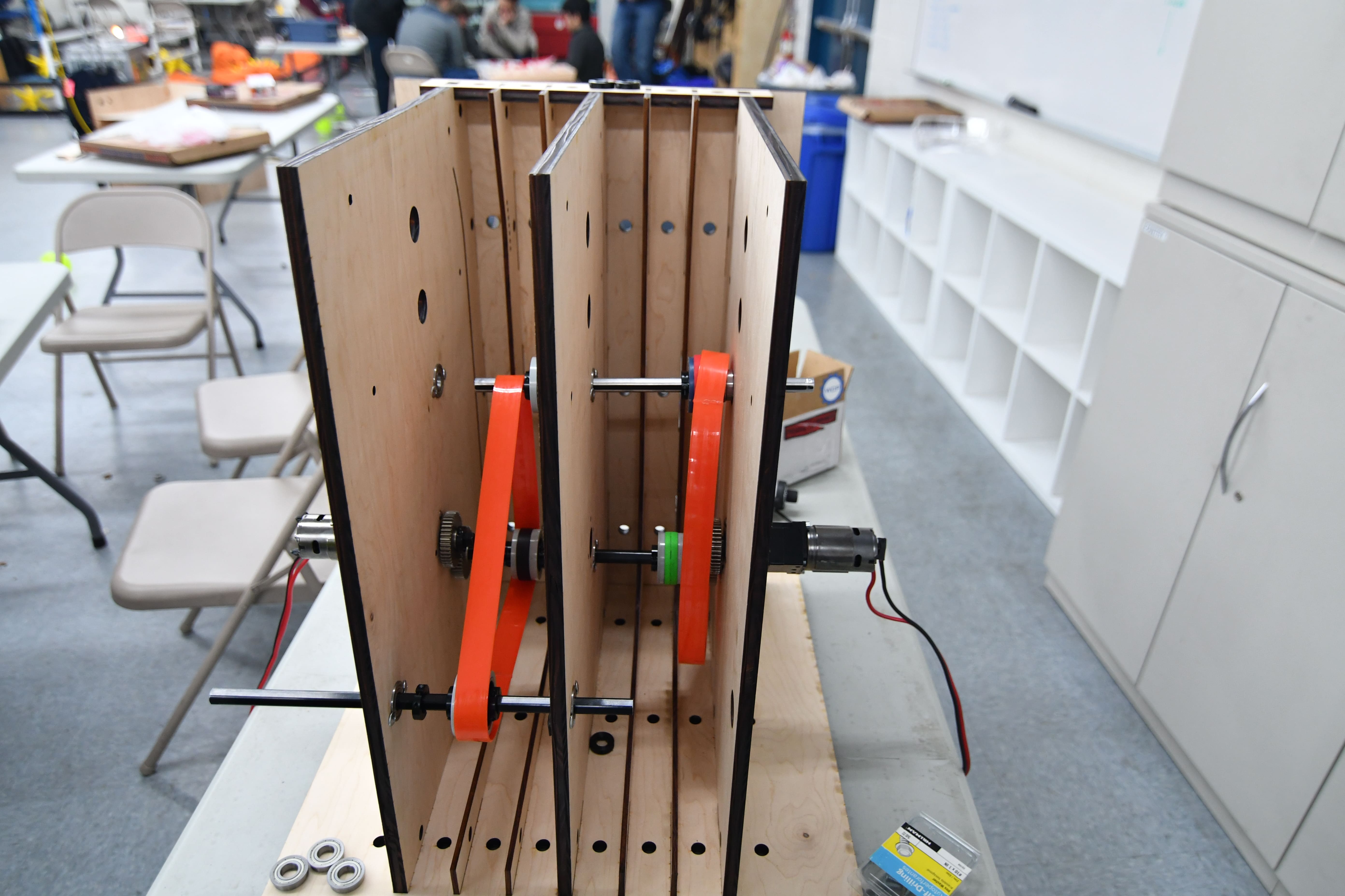
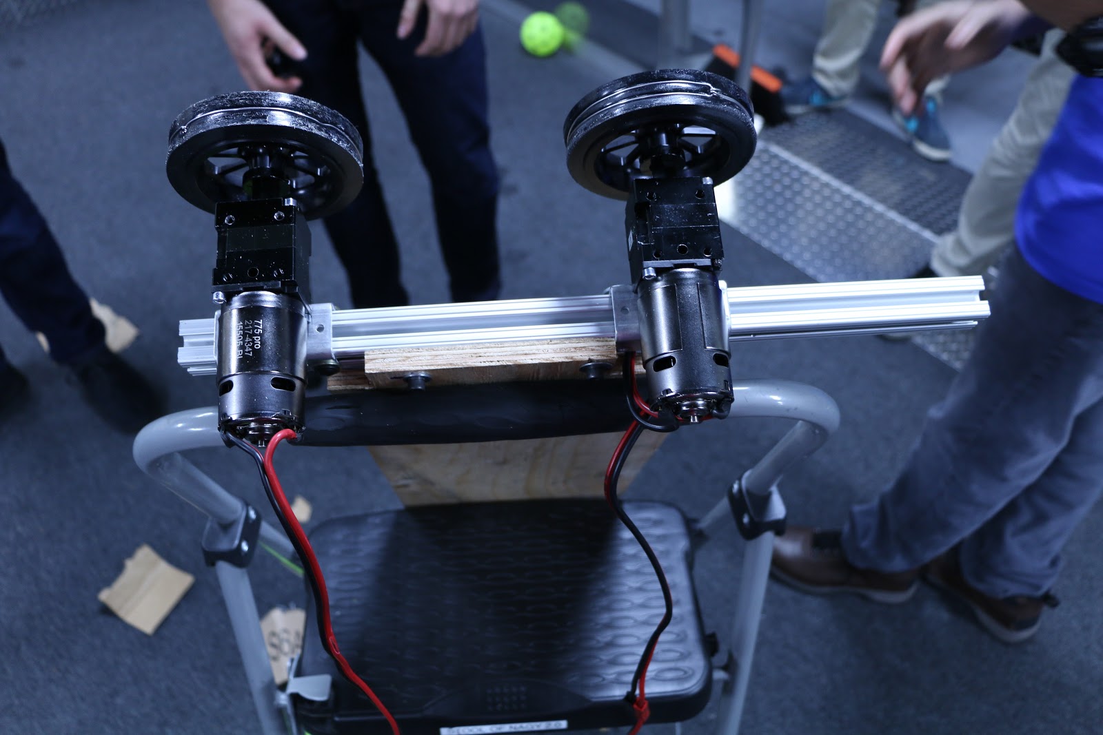
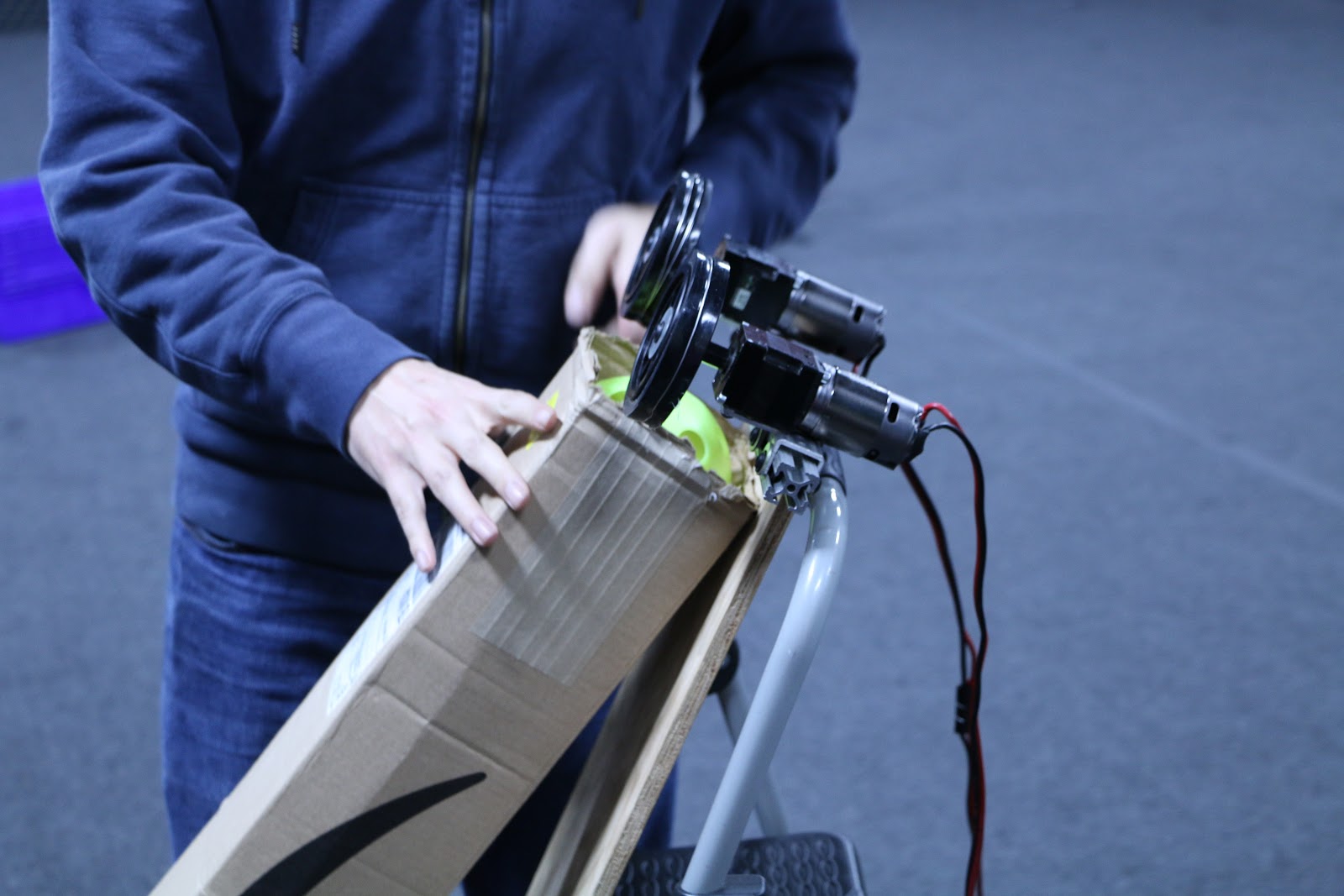
Backspin Flywheel Shooter
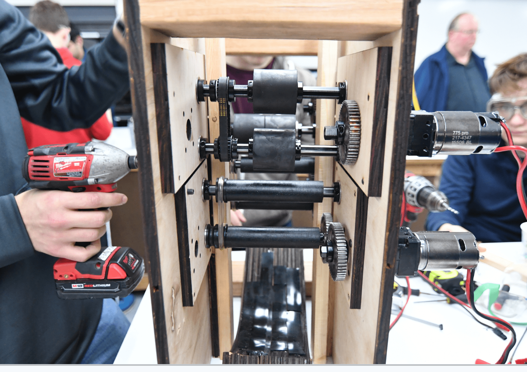
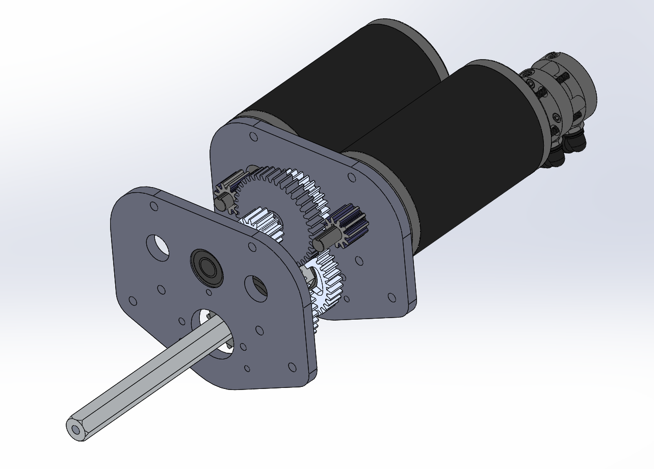
After we decided on using a backspin flywheel, we began prototyping a new version that has two channels side by side with a more robust gearbox. This setup shoot allow us to experiment with different variables to determine the best control loop to fire two rapid streams side by side and avoid mid-air collisions. We wanted to remove the inefficiency of the VersaPlanetary gearboxes from our prototypes, so we designed a belted gearbox. We wanted to replicate the 3:1 gearbox which we used for our prototypes, but due to part limitations, could only build an 8: 3 design. We decided that this was close enough to our previous designs and CNCed the parts. We assembled the gearboxes, implemented a polybelt feeder, and added an encoder onto the shooter shaft. After running the gearboxes, we found them to be slightly constrained, but they work and should better replicate our actual shooter. They currently have 4 775 Pros, but we can easily add or remove more motors (max 6). As soon as we get the programming sorted out, we should be able to tune and test this flywheel.
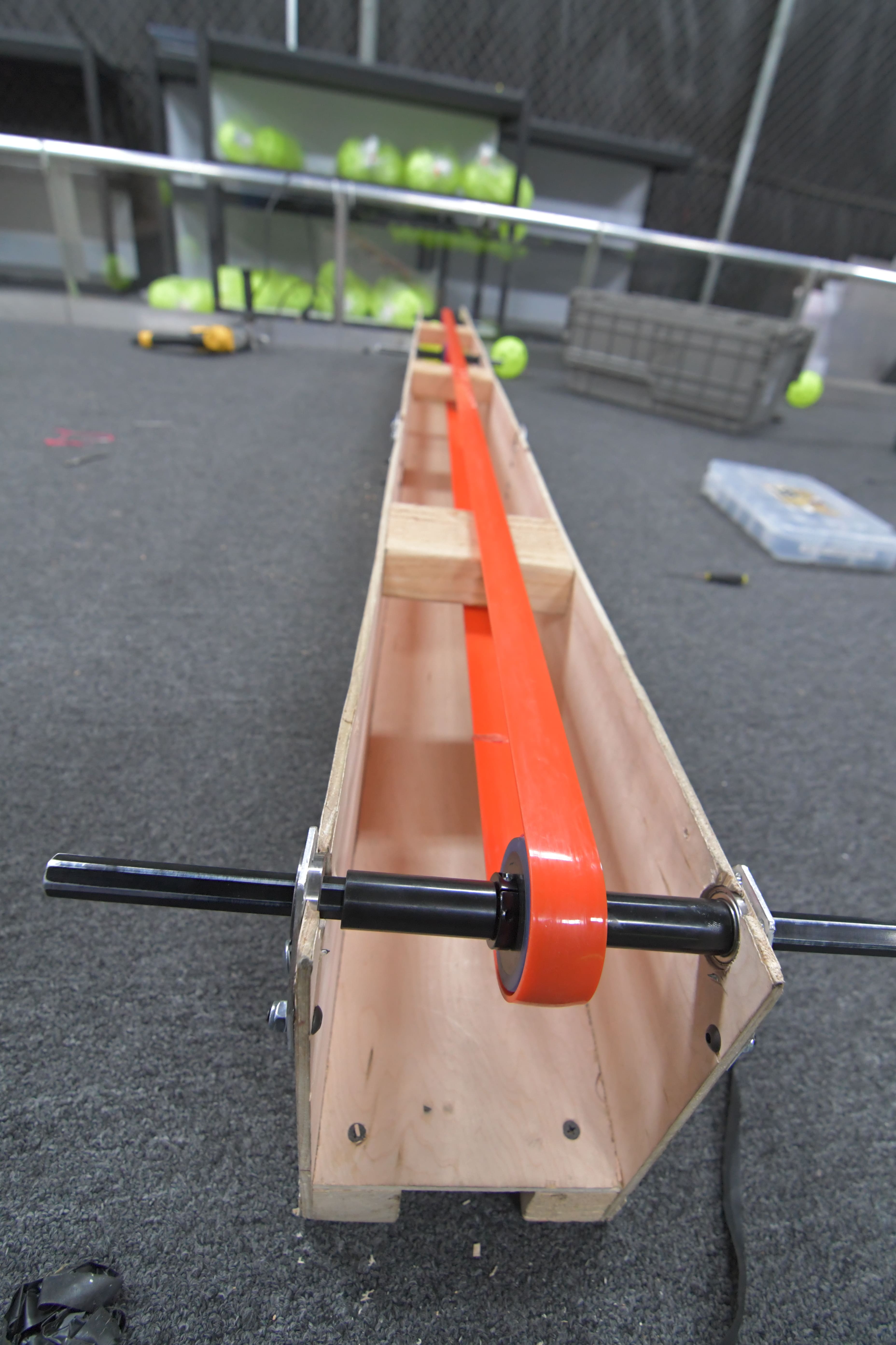
Hopper Conveyor Belt
Today, we also worked on the hopper conveyor assembly. It is currently angled at 5 degrees and has a 3:1 reduction. Using polybelt, it feeds balls into the feeder leading up to the shooter. A funneling feature still has to be incorporated and the assembly itself may be changed depending on results from the hopper prototyping efforts.
Feeder
Today, we worked on the feeder. Because we were unable to get the previous iteration of the feeder to run smoothly with the output holes, we decided to reduce that number to two and make a few other small modifications to the general design. This new version was then designed and constructed, but we found that the improvement was not as significant as we originally imagined it would be. In fact, we still had problems with the motors burning out and we really struggled to get a lot of balls to run through the system. In order to solve this problem, we tried a couple of things. First, we tried adding zip ties to some parts of the roller, but this simply caused jamming. Second, we tried increasing the spacing between the two output holes as making them significantly more defined. This, unfortunately, did not help that much. Finally, we tried using a drill with some wheels on the end to agitate the balls, somewhat like a KitchenAid mixer. This helped a bit more, but we still reached the conclusion that it was simply a bandaid to a bigger problem.
Manufacturing
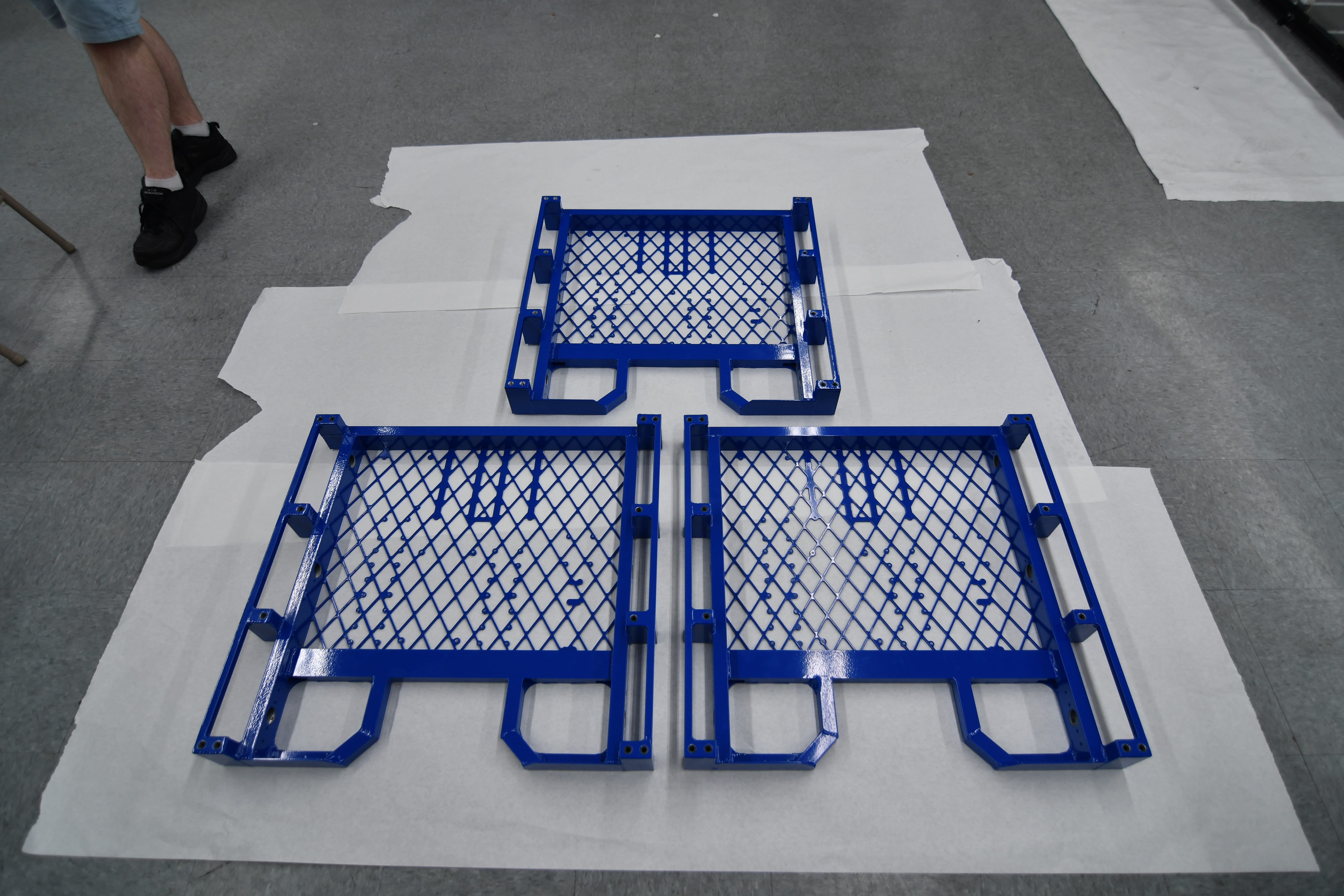
For these two builds, we manufactured all the parts for the drivebase and began assembly. Because of design changes, we manufactured all the parts for the bumper mounts on the manual mill. We also prepped the belly pan by countersinking the holes for the rivets and deburring it after getting it from the water jet.
Programming
Shooting Control
Today, we began to brainstorm better ways to control the flywheel, and we arrived at the following scheme (which we call the JRAD Controller):
v[t + dt] = kf + kj * dt * (kLoadRatio * setpointSpeed – curSpeed)
Where dt is measured cycle time, kj and kLoadRatio are tuned/calculated, and kf is set to some constant like 8 (Volts)
This equation represents the initial version of the JRAD controller (named after Jared, who made the equation). This version is actually incorrect, and next build we will be adding an additional term to make it an integrating controller as opposed to a proportional + constant term controller. This new equation will be:
v[t + dt] = kf * setpointSpeed + v[t] + kj * dt * (kLoadRatio * setpointSpeed – curSpeed)
Where v[t] is the previous cycle’s output in volts, and where kf is multiplied by the setpoint so that it works at more than one speed
What this controller does it that it anticipates the drop in RPM during a stream of balls, and increases the RPM set point accordingly. This adjustment is the kLoadRatio, which is the key feature of this controller.
To tune the controller, you would start with kLoadRatio at 1, kj at some nonzero small number, and kf also at zero (kf allows the controller to reach the steady state faster, but is never necessary). Here is the initial scenario:
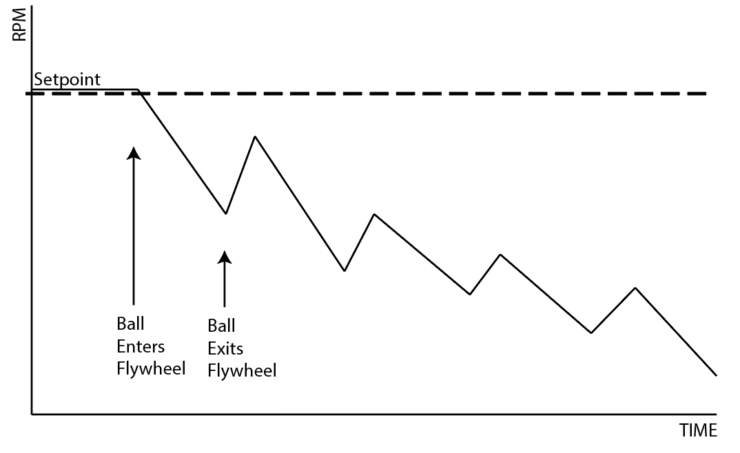
The difference between the dips when balls hit indicate that the controller is not tuned correctly. Each valley should be at the same height, even if it is below the steady state. KJ should be increased in the above scenario. If the valleys increase over time, then KJ should be decreased. Eventually the RPM vs Time chart should look like this:
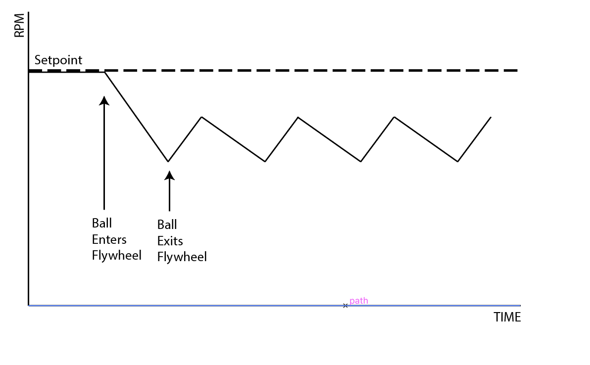
This is definitely better because the balls are consistently exiting at the same speed, however we aren’t getting to where we want to be when we shoot. When this is achieved, we can finally calculate KLoadRatio. To do this, we take the setpoint and divide it by the Lowest RPM, which should now be constant for every ball. This yields a number greater than 1. Now the output of the function looks more like:
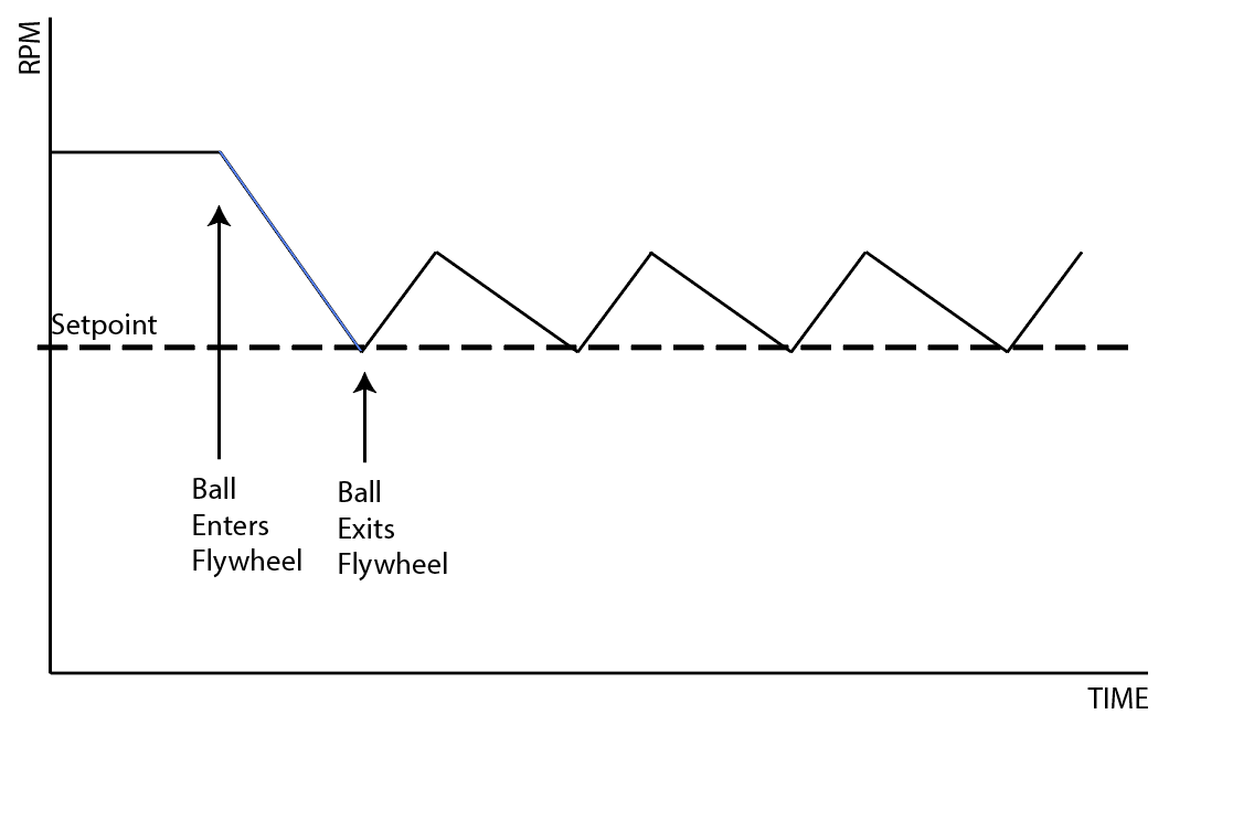
Notice that the steady state is now greater than the set point. This is because it anticipates that the RPM will decrease when a ball contacts the flywheel and it increases the speed before the ball hits so that the speed is correct when it actually is released from the shooter.
Here are videos of the testing we did.
Robot Vision
Today, we found the correct equation for using the camera matrix and distortion coefficients and undistorting an image. We found the equation in this Wikipedia article. This is working pretty well. Now we just need to implement it into the robot code, and it should be done.
We also discussed whether or not the PIXY Camera would be useful for the targets this year. Right now, the current plan is to use the pixy for the gear vision target, but not the boiler. We believe that the low resolution of the Pixy camera would lead to a high error in locating the boiler, and since the margin for error is so small for our shooter prototypes (see Prototyping section of this blog), we need to have a more accurate system. Thus, we resurrected the old vision system using smartphones from last year, and initial tests are promising. We need to tune the OpenCV, but we were able to get it to reliably filter the boiler target:

Also, we refactored the SPI communication driver for the PIXY Camera so that it is better integrated into the codebase and so that it can support multiple cameras.
Autonomous Path Following
Today, we continued work on the autonomous pathing system. We finally got the code to the point where we were able to deploy it to a spare drivetrain and test. We began by tuning the PIDF constants for the drivetrain and setting constants for the wheel radius, drivetrain width, and several pathing parameters. We had to make many several bug fixes and changes to our code, including rewriting the circle function in out AdaptivePurePursuitController class. We also faced several hardware problems, like the encoders falling off and one of the gearboxes breaking.. However, by the end of build, we were able to get the robot to drive along curved and straight segments of the path with a decent margin of error. There is still much work to be done on the pathing system, including improving its accuracy and implementing turns in place.
FRC Day 11 Build Blog
Day 11: Prototypes and Drivebase
Prototyping
Shooter
Today we worked on duplicating the single wheel backspin flywheel with 4″ fairlane wheels. We wanted to test the accuracy and plausibility of two side-by-side flywheel shooters, so we built another shooter. We also altered the first backspin flywheel shooter by replacing the side plates, which allowed us to put both shooter motors on the same side. This alteration was made to make the two side-by-side shooters compatible
Hopper Feeder
Today, we began detailing the hopper feeding mechanism. The current plan is to have it powered by two 775 pros with a reduction and to power both the front and back rollers via friction with the polybelt. The feeder is slightly angled and will include a funnel consisting of two tubes angled towards the middle of the back roller. The feeder will also rotate on the same axis as the intake. Rotation will be necessary to access the electronics on the baseplate between matches (i.e. Switching batteries)
Shooter Feeding Trough
Today, we built a second trough and added 775 Pro motors with a 3:1 reduction on both. While running, a polybelt moves the balls at an estimated 18 balls per second.
Intake
Today we finished assembly of the new intake prototype without a ramp and tested it out. We found that there was too much compression between the intake rollers and the floor/bumper, so we adjusted the mounting of the intake accordingly. What we found was that the center drop of the robot was enough to upset the outer roller’s compression such that when the robot leaned back, it would not pick up balls. Of course, this was a big problem, so we made the intake pivot around a point inside the robot, very similar to how the real one would. By having the intake itself able to pivot, we think that it’ll be able to move up and down accordingly as we drive into dense clusters of balls, fixing the issue of the intake bogging down. We finished assembling the intake, but have yet to test it. Our first job on Friday will be to get more tests running, and we’ll go from there.
Manufacturing
Drivebase
A group of students started manufacturing the parts for the drive base so we can send it out for welding next week. We were milling the parts for the bumper mount on the mill and ran some other parts on the CNC.
FRC Day 10 Build Blog
Day 10: Shooter Improvements & More
Prototyping
Backspin Single Wheel Flywheel
Today, we finished the 4" Fairlane Single Wheel Backspin Prototype that we started on Saturday. We tested for the entirety of the build and received great results. While single shot accuracy was consistent, when we started pushing in balls at a higher speed, we found that the shooter was somewhat inconsistent. In exploring other options for more consistent feeding, (and by consequence shooting) we decided to change the VersaPlanetary gearbox running the polybelt feeder from a 5:1 gear ratio to a 1:1 ratio. We found this speed to be much more efficient. At the end of the night, without pushing the balls (so solely gravity fed), we managed to shoot around 25~ balls. After missing the first shot or two, we managed to make every subsequent shot. While this only shot at around 2-3 balls per second, it is a first step towards proving our design. We found the precision to be incredible, but more importantly the rate of fire was impressive! This was most likely due to the extra mass of the wheel resulting in inertia to counteract fluctuations in rotational speed as balls compress against the wheel. We began making a second iteration of this prototype in an effort to put it next to the previous working one. We would then shoot them in the same direction and verify that two shooters side by side is a feasible option for accuracy and rate of fire. We finished laser cutting the new parts, acquiring the materials, and sorting out all the tools. We only need 2 more 3:1 VEX Planetary Gearboxes, and then we can assemble the prototype and test.
Testing:
Intake
Today we worked on a new and improved design for the intake. We CADed new sidewalls with updated geometry, in order to get rid of the ramp and make the intake easier to deploy. We laser cut the sidewalls and are almost done assembling the new prototype. The plan for the future is to finish it early on Wednesday, then run tests to see how effective it is.
Intake Feeder
Today at the lab, we worked on the feeder for the intake. Unfortunately, the whole process took a long time because we struggled so get the vertical portion of the feeder to spin at all due to efficiency issues with the design. Once we did get it working, however, we modified the lower roller in order to increase the spacing between it and the vertical roller. Though this would be effective, but generally we found that the current design simply needs too many modifications, so it would just be easier to do a complete redesign. The next step is to look into other feeder systems that are potentially more efficient and faster.
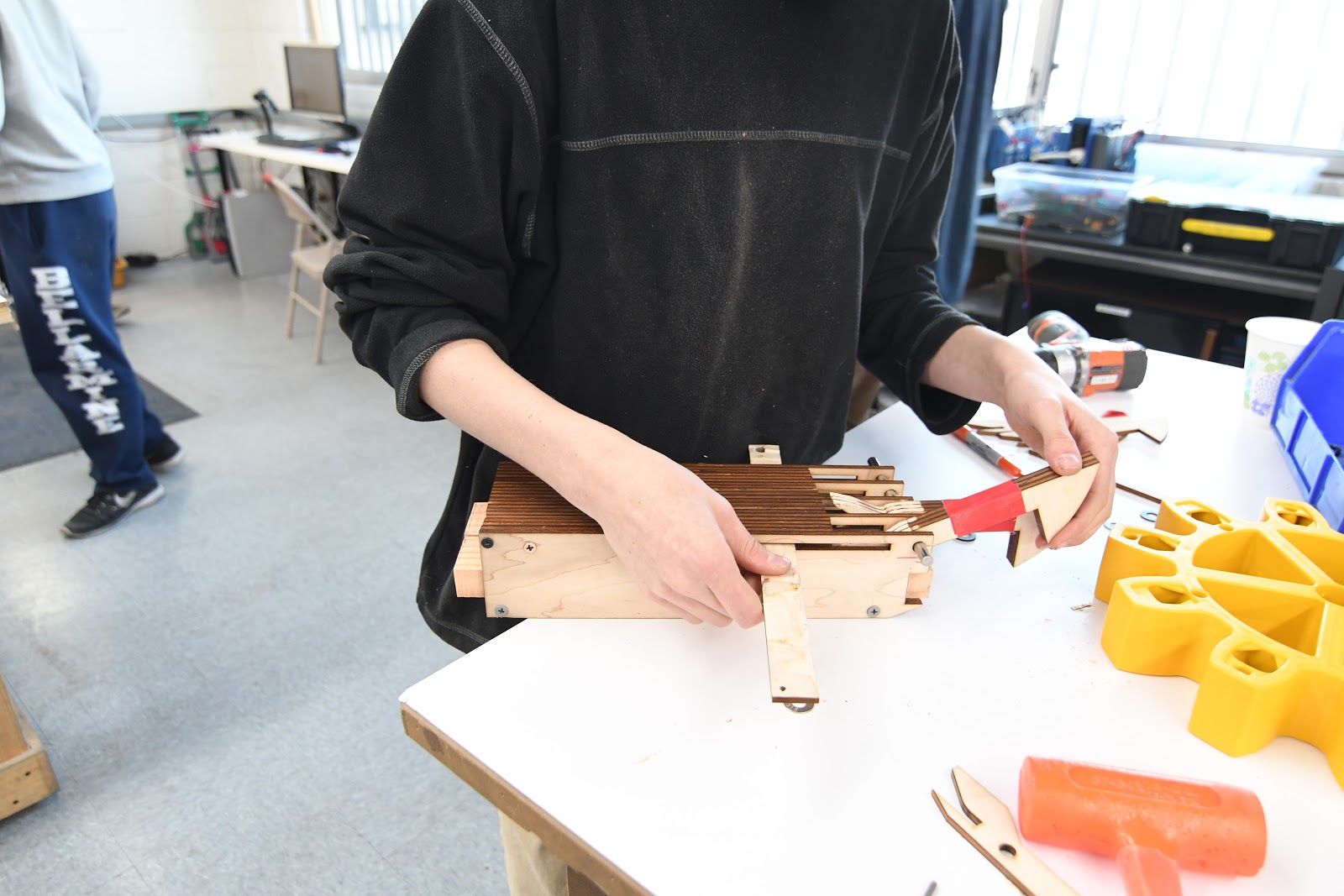
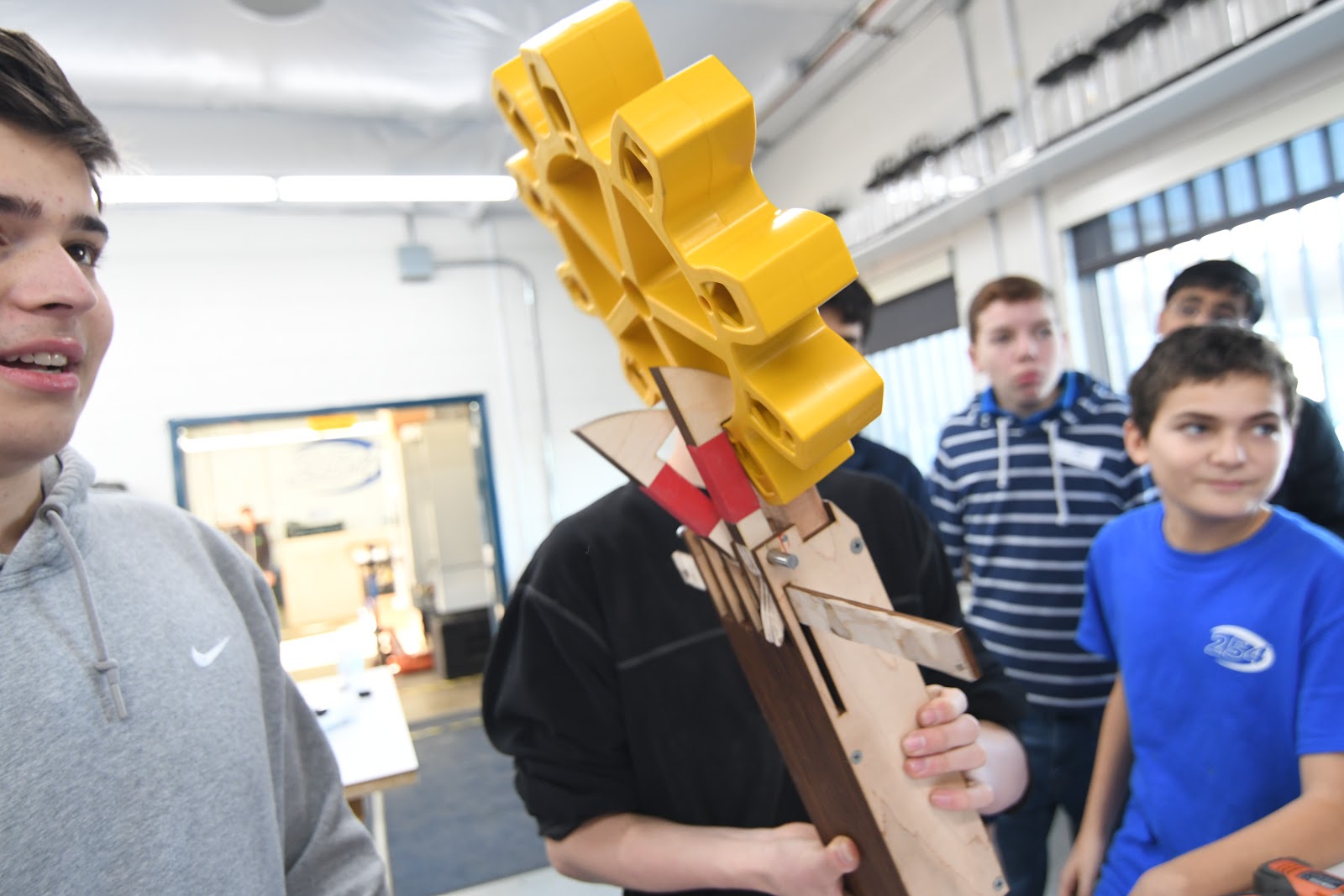
Rope Climber
Today, the team working on the rope climbing switched the previous 775 pro motor for a CIM motor and succeeded in climbing the rope. We first laser cut a new piece of wood that would connect to a cross bar on the robot holding the motor and comb shaft. We moved the holder for the motor and shaft one inch up to provide clearance for the motor as well as give the comb more room away from the crossbar. After this, we assembled a CIM motor planetary gearbox in which we geared the motor 1:9 and this ratio was also later increased through the gears on the shaft to 1:45. This proved to be enough to lift the approximately 30 pound previous drive base of our 2015 robot, Deadlift. Without success, we found that undoing the rope on the comb proved to be very difficult and time-intensive, so went back to the drawing boards and found that a velcro design could work out well while taking less time to undo. We will assemble and test this during the next build.
Testing:
Programming
Testing Shooter Prototype
Today we made leaps and bounds with the shooter prototype. We were able to score 30 balls consecutively feeding into our dual-motor flywheel shooter prototype. To do so, we fine-tuned the PIDF constants in the robot code to ensure that motor speed would remain constant even with the load from the balls, which ensures more consistent, accurate shots. This is a breakthrough for our shooter prototypes, the first time where we’ve been able to make a majority of shots from a stream. We still have to improve the firing rate of our prototype; we were firing at ~3 balls per second.
FRC Day 9 Build Blog
Day 9: Flywheel and Prototypes
Prototyping
Topspin Single Wheel Flywheel
The topspin shooter continued testing today with several small changes made throughout the build. We remade yesterday's prototype and varied the hood length to see how it affected accuracy. We started the day by testing the 4" flywheel with top spin. We took the working design, and redesigned the prototype to not be adaptable, and in doing so we also designed an integrated feeder. This design worked relatively well. We iterated on the optimal amount of wrap on the ball, starting with around 120 degrees, and going as far as 80 degrees, without testing further. As we iterated and continued testing, we realized the difficulty of packaging a topspin flywheel, so unless we are able to show that topspin is more consistent, it is unlikely that we will use it in the final design. We also tested a backspin 4" flywheel by simply rotating the shooter. The design worked, but needed further optimization. We set upon further iterating on this by CADing an entirely new design.
Backspin Single Wheel Flywheel
Today, we remade the single 2" Fairlane Flywheel prototype, but this time we fixed all the little bugs from before as well as added two more 2" wheels in the exit. This concept was to see if it would make the shot more accurate, but it didn't pan out. We reverted to the single wheel design, which worked beautifully. This backspin shooter was really consistent and accurate for the first successful iteration and it also makes packaging the shooter into our robot much easier. We also worked on designing a three-parallel-shooter prototype that would have three of these shooters side by side for maximum shooting rate..
Drivebase CAD & Design
We continued work on drive frame detailed design. Other team members started exploring space claim models for the entire robot, including the hopper, shooter, gear mechanism and drive train. We also looked at possible packaging for the topspin shooter that was working well. We decided that for simplicity, the ball feeder chute on the rear of the robot should not deploy over the bumper, and that it is better for it to stay rigid for consistent ball feeding. We still plan to deploy the hopper on the front, and possibly sides, of the robot.
-min.jpg)
-min.png)
Field Construction
We cut plastics and installed the top of boiler so that more accurate shooter testing could proceed.
Manufacturing
We will be continuing our work on making drive gearboxes. We finished de-tabbing gearbox plates and started making gearbox standoffs. Several students continued on mill/lathe training with test parts.
Programming
We restructured the robot code to offload control of the drivetrain from the Drive subsystem file to the main Robot Java file. The Drive system’s code runs every 1 ms, while the robot’s code runs every 5 ms. The driver station sends and drive data every 5 ms, so moving the code saves considerable processing power. This also allows for other functions to be implemented in the Drive subsystem.
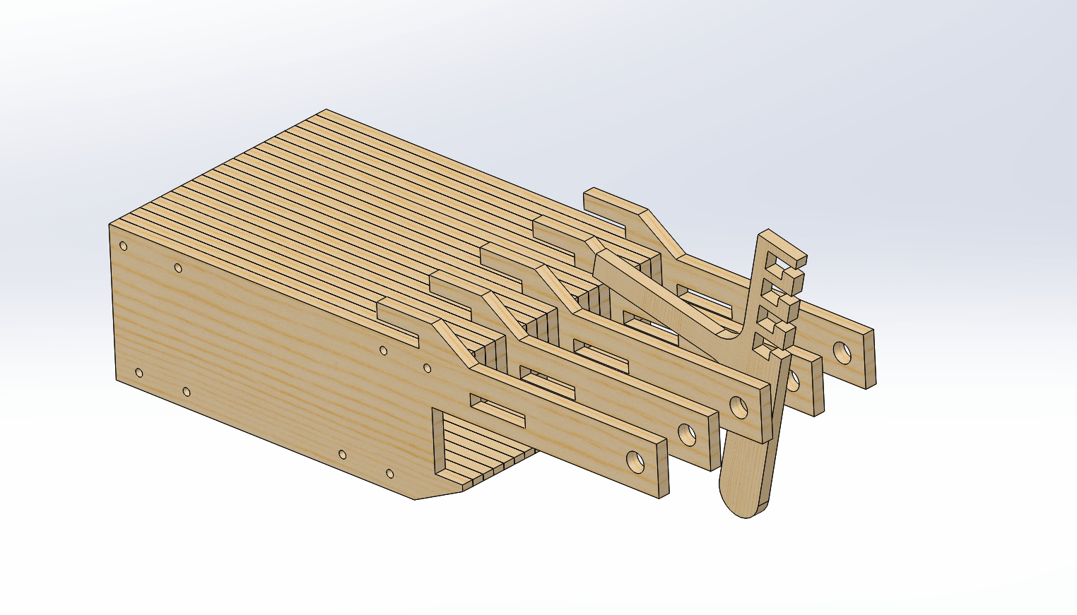
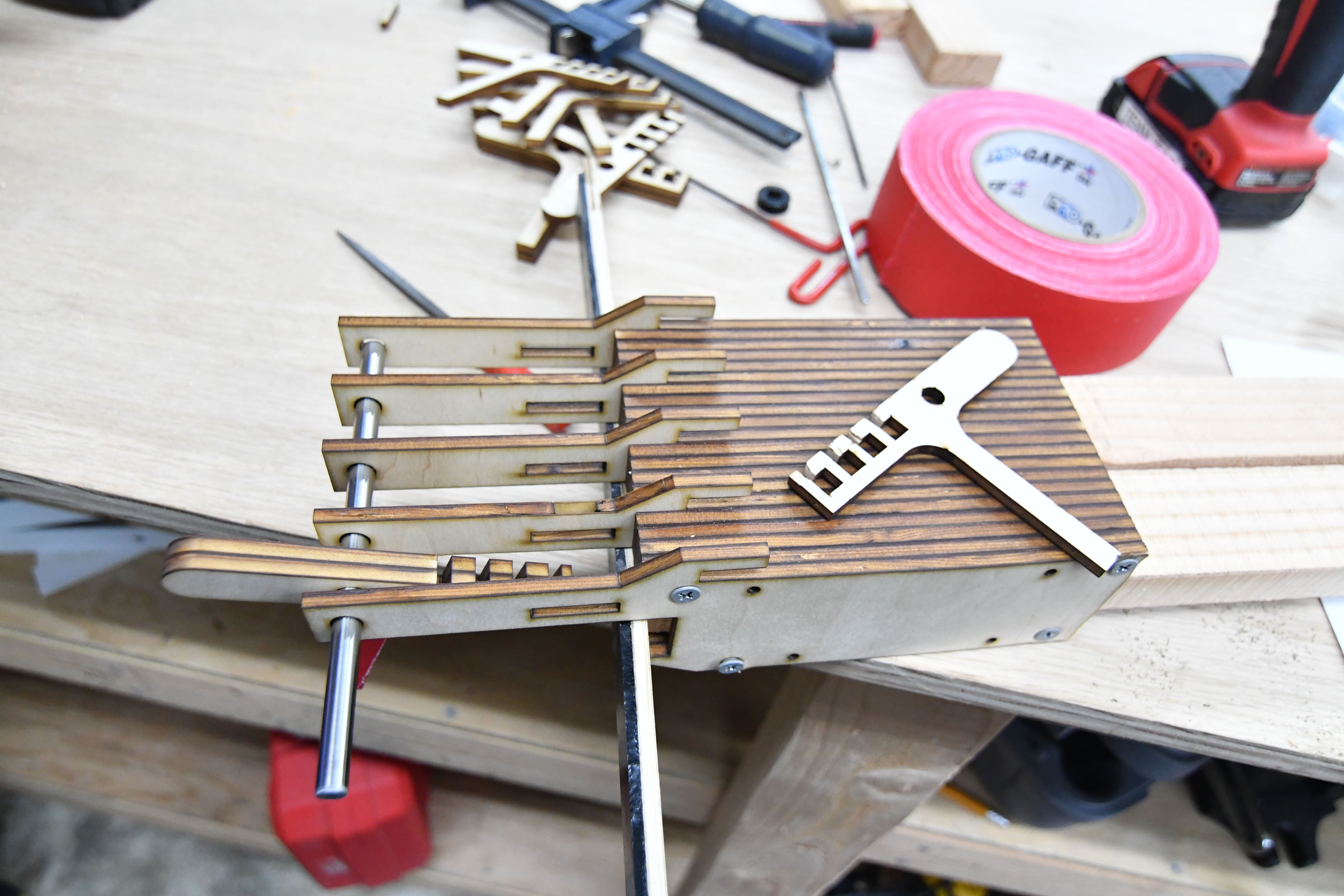
Following our all-hands meeting yesterday, we finished the autonomous routine visualizer, which allows us to design and visualize an autonomous routine using a series of points. We also finished a parser that turns the visualizer output into usable robot code. We also implemented an adaptive pure pursuit controller, which helps the robot correct any deviations and return to its pre-planned route. This requires an odometer to track the robot’s distance travelled and heading, which we also implemented. We are currently establishing the groundwork for the robot’s autonomous routine, which we will implement when we have a final robot.
Camera calibration
Today we finished camera calibration code. It works really well, and now outputs the distortion numbers to a .txt file for easy access. Now, we are working on incorporating that into the SPI code so the Roborio has access to the undistorted image data. We need to figure out how to undistort the image while keeping it in a RAW format.
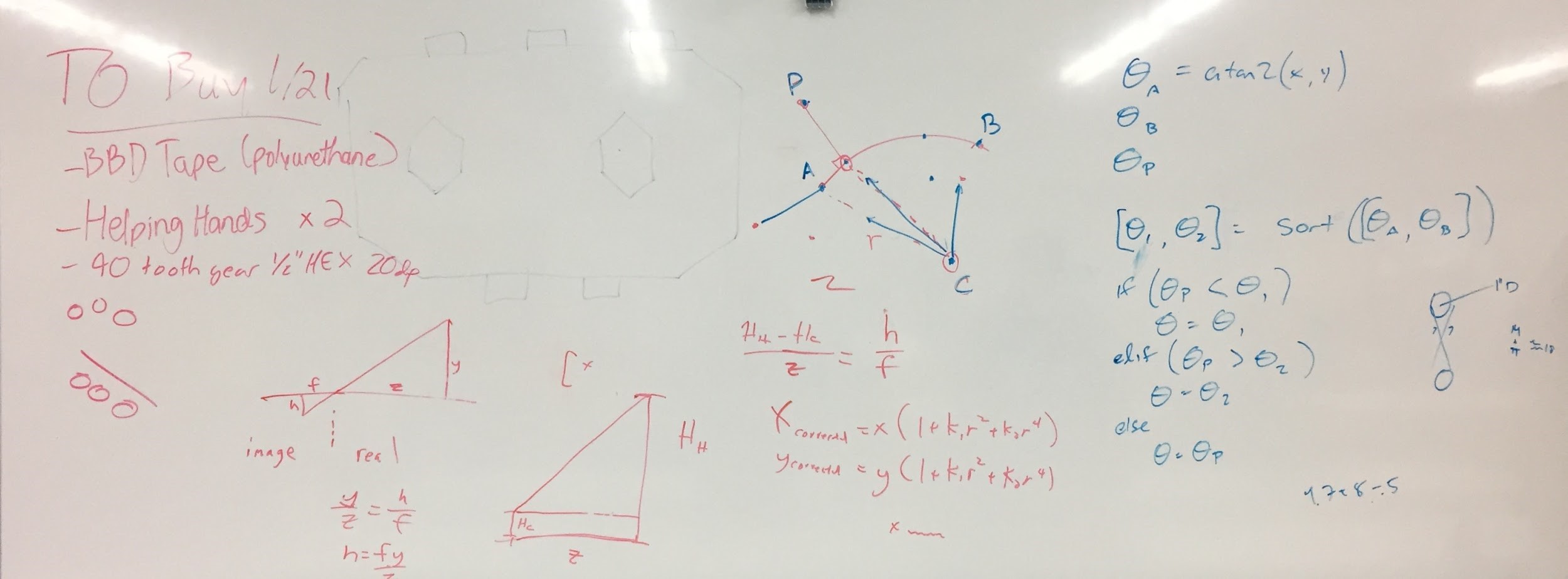
In addition to receiving calibration results, we discussed how to then take these calibration constants and apply them to remap the raw image coordinates to adjusted ones that map to physical locations on the field. We consulted a handy opencv guide.
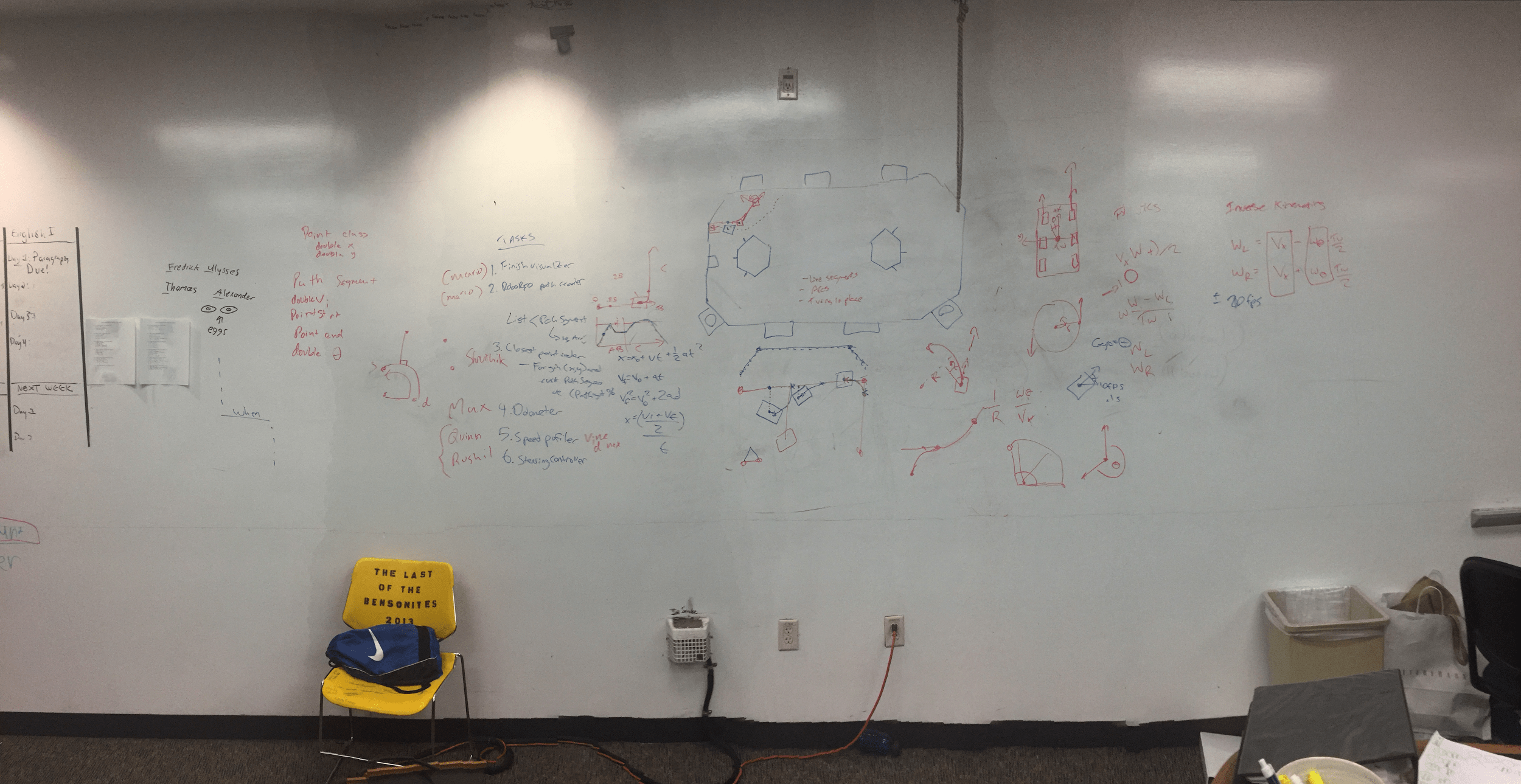
Here's the picture of our whiteboard discussion:
Programming On The Prototypes
A lot of progress was made today with prototyping. We wrote new code to add a closed PID control loop to the feeder of the new overhand/backspin prototype and we returned constants to work with the new flywheel. In doing this, we discovered numerous bugs in the constant setting code and we have remedied many of them. Most of the time was spent supporting the prototyping effort with various control tweaks to maximize performance.
FRC Day 8 Build Blog
Day 8: Flywheel
Prototyping
Topspin Single Wheel Flywheel
Today, we iterated on our flywheel prototype. We decreased compression by around a half inch, and found drastically improved results. Our first test had over 90% accuracy. We attached a second motor to be able to test high throughput shooting well. We made our feeder perpendicular to the shooter, and found some shot inconsistency from balls later in the feeder. We realized that a gravity fed shooter might not work well, and added a powered feeder shaft. Our shot-shot consistency improved greatly for high throughput testing, but still isn't excellent.
Testing:
Backspin Single Wheel Flywheel
Today, we worked on a single 2" Fairlane wheel flywheel with 1/4" compression fed by a polybelt feeder, powered by a 1:1 VEX Planetary Gearbox and Motor. The wheel – powered by 2 Planetary Motors – had lots of power, but was very inconsistent. Moving forward, we will want to constrain the shot on the sides as to avoid inaccuracies from side to side (this will most likely be with 1/8" polycarb sheets double-stick taped on). To help the ball shoot more accurately as it exits, we will either shorten the hood so that the ball is in contact with the wheel right before it exits. We may also try to add rollers to improve the shot accuracy. We also had trouble with the polybelt feeder, as the polybelt (which had too much compression on the ball) would skip along the ball as it pulled it up, getting worn down and rendered virtually ineffective in the process. To fix this, we plan to move the feeder out slightly to get the right amount of compression and also have a curved backing so that there are no dead zones in the feeder system. We also plan to make another prototype with a similar design, but less inaccuracies in alignment of the wheel and feeder.
Fuel Intake
Today we made good progress on the intake. We added two motors (775 Pros) and changed the gear ratio to an overall 3:1. The results were significantly better than the previous test with 1 motor; now, driving at full speed into a dense pack of balls, we were able to pick up almost all the balls and hold them in our hopper. However, this current design uses a small incline right in front of the bumper to help pull the balls up and over, which we would like to get rid of for the final design, because it makes deploying the intake much more complicated. We created a new prototype that does away with the ramp by changing the bottom roller geometry relative to the bumper, and from initial testing, the results looked very promising. More prototyping is needed to see if the new design with no ramp is effective as the previous prototype; however, as the intake nears completion we may prioritize finalizing the shooters.
Testing:
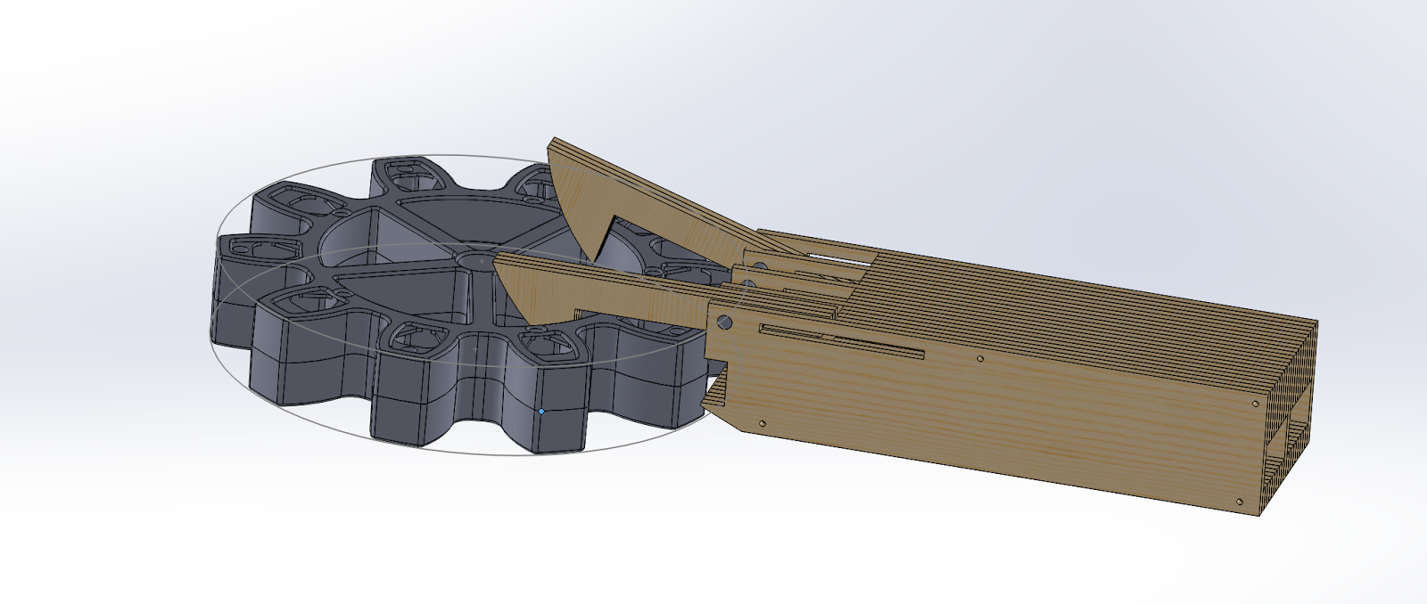
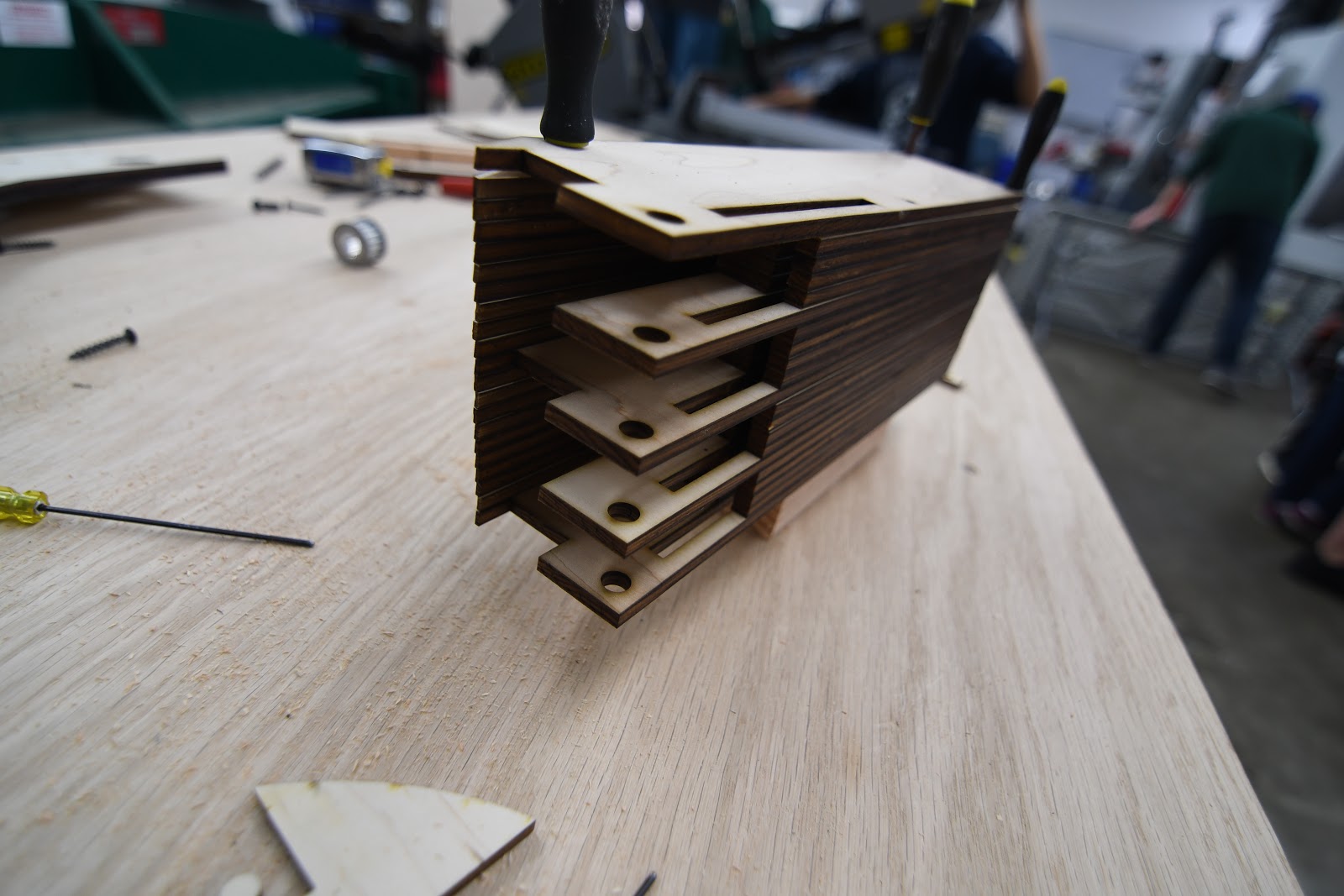
Gear Intake
Today we tried out a completely new design for the gear intake. Instead of placing the pivot point for the hook very close to main body of the grabber, today’s version switched that pivot point to the very front part of the hook. Feel free to compare the picture below to the pictures from the last couple blogs to see the change in design.
Although we did not finish fully assembling the new design, we believe that this new version will give us a significantly better grip on the gear.. Unfortunately, our initial impression after assembling part of it at build tells us that this new design might actually take up even more space than the previous version, which might outweigh the extra grip. The next step in the development process with involve finishing the construction of this design and evaluate possible areas of improvement. Once we have multiple gear grabber designs working at their full potential, we will compare the different versions and begin designing a metal version for the robot.
Drivebase
We made adjustments to the drivebase CAD by moving down the crossbar to be flush with the baseplate while cutting out slots for chain runs. We also changed the corners on the rear to have a 45 degree slant for better gear intake and made it with two pieces of 1×1 tubing. Moving forward, the last electronics (pcm, vrm) and pneumatics (solenoid/manifold, compressor) have to be finalized in addition to final dimensions.
Programming
Today, the programming subteam discussed robot motion control with Jared. Moving a robot from point A to B requires waypoints, curvature, and physical constraints of the robot. For instance, a robot cannot instantly accelerate from standstill to full speed, and it cannot instantly decelerate to a standstill without damaging its gearbox components or slipping the wheels. Motion profiling allows the robot to move in a controlled fashion, minimizing acceleration and deceleration.
We also discussed factoring in obstacles like slippage and wrinkles in the carpet. In techno-speak, we would maintain an “odometer” to track our robot’s total movement, then we would calculate the robot’s deviance from the actual path. We would then calculate the closest point on the path, calculate the distance from the robot to the point, then draw a circle using the point as the center and the distance as radius. This path would be used to bring the robot back on track.
We divided the programming subteam up into six projects: finishing the autonomous mode visualizer, creating a RoboRIO path reader that would parse the visualizer output, calculating the closest point, creating an odometer, a speed profiler, and a steering controller. Meeting minutes are in the picture below:
For the PixyCam, we made significant improvements with the SPI interface. The interface works, but with a few bad bytes. We should be able to fix these kinks soon. Also, we’ve made leaps and bounds forward with camera calibration, and distortion is much less of a problem.
FRC Day 7 Build Blog
Day 7: Shooter and Prototypes
Prototyping
Double Wheel Flywheel
Today, we added wooden bars to prevent the ball from moving back and forth, as well as moving the polycord to the outside to limit disturbance. We then tested it, and it was very consistent and accurate. After fine tuning for a time, we realized only one flywheel was getting powered in testing. We then connected the other flywheel and retested it. The shooter’s speed and accuracy was improved greatly with the change.
Testing:
Single Wheel Flywheel
Today we worked on a single wheel flywheel, independent of Dropshot. We began by cutting a design built to be extremely modular. After assembling the design with a 3:1 gearbox and powering directly from a battery, we found it to shoot far too fast. We changed the gear ratio to a 5:1 to account for this, and it improved drastically. In the next step, we changed back to a 3:1 gearbox, and attached the prototype to a Roborio and speed controllers. The prototype had too much spin, and did not grab the hood. We added polyurethane strips onto the hood, and this improved the compression and grip. The 4" fairlane wheels we were using started to come apart, so we replaced them with the wheels we used on Dropshot last year. We tested those, but found there to be too much compression. Next build we will most likely continue iterate to iterate this design to find the most effective qualities and use those.
Testing:
Retrofitted Dropshot Shooter
During this build, we found that the retrofitting Dropshot with a shooter proved useless (the other single wheel flywheel proved much more viable) and unrepeatable, so we abandoned this effort.
Intake
Today we did our first testing session of the intake/hopper combo on the 2013 drivebase. After a few simple iterations (small geometry changes, etc.) we were able to intake balls pretty effectively, although not as fast as we would have liked. When we drove the robot at full speed into a dense cluster of balls, we knocked away a considerable amount of the balls because the intake couldn't keep up with the speed of the drivebase. We were unable to effectively speed up the intake by using less of a gear reduction, because the intake would brown out and trip its breaker when the hopper was filling up. To solve this issue, we plan to add a second motor to the intake and further decrease the reduction (to 3:1) in order to intake fast enough. If all goes well, we should have an intake that meets all our goals by Friday. As a refresher, the goals for the intake are to be able to drive full speed into a cluster of balls, and have any ball that touches the front of the robot be sucked in. It also needs to stay compact in terms of depth, so that we can maximize the hopper space with the limited volume we have.
Testing:
Programming
Camera Calibration
While working outside of the lab, some programmers achieved initial success with the camera calibration code and were able to view calibration frames from a webcam, but were unable to link that to the PIXY camera yet. The software to communicate with the camera has been developed separately, and will need to be linked in, and then finally some performance issues will need to be addressed.
Camera Communication
Today we continued work on interfacing the PixyCam with the Roborio over SPI. Now that we're reading actual data from the Pixy, the challenge was to start making sense of that data. For each frame, the Pixy sends a list of the bounding boxes of detected objects ("blocks"). The information for each block is in a regular, consistent format. However, after debugging the raw data from the Pixy, we found that blocks (and frames) seem to begin at arbitrary places in the stream of bytes, with zeros (00) filling the gaps between them. We've modified and build some new functionality behind the scenes to allow code to handle this; a little more debugging and the robot should be getting a consistent flow of vision information.
FRC Day 6 Build Blog
Day 6: Shooter Prototyping
Prototyping
Double Wheel Vertical Flywheel
The design of this shooter is based around two rollers feeding into two wheels that spin rapidly, compressing and shooting the ball into the goal. When we tested this prototype, we found it shot very wildly. We figured we needed another wheel above the first two to act as an active hood in order to improve accuracy. We then cut into the plate to make room, and lasered new plates. This new design worked slightly better, but it needed more compression, so new plates were lasered and assembled; however, we ran out of time to test it and will test it next time we meet.
Testing:
Double Belt Shooter
Today, we worked on prototyping a polybelt shoot using a design which was designed outside of lab hours. We began by modifying the design to work alongside the polybelt, as the original design assumed that the center to center distance between shafts could change. After changing the design and cutting new plates, we assembled the shooter. We used a 775 Pro motor with a VersaPlanetery gearbox with a 5:1 reduction. After testing it and finding that the roller speed was too slow, we replaced the 5:1 with a 3:1 and found an immediate improvement. We also increased the compression on the balls on our feeding mechanism by adding polyurethane strips to our feeder plate. While our shooter was able to shoot balls, accuracy was low and there was a significant amount of variability between shots. We were not confident about what the issue was, but we now are sure that we need to provide more energy to the balls and in a more efficient manner.
Testing:
Retrofitted Dropshot Shooter
Early in the season we modified dropshot to shoot the fuel balls. We are now working on a new version that will have a powered feeder and new rails to shoot the ball. We haven't finished assembly yet.
Programming
Robot Programming
We debugged some code that was written last build and got it to run on our prototype drive base and we also fixed an issue on our other development board by replacing the radio. Also, the web configuration code that we used in 2015 was ported to this year’s code base for easy constants configuration. With all of the prototypes we were working on, the github started getting messy, so we cleaned it up by branching and adding more files to the gitignore.
Camera Calibration
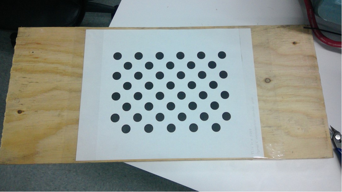
Today we worked a lot on Camera Calibration. In the morning, we got some code that allows OpenCV (the library we use for calibration) to directly communicate with the Pixy Cam. Other than some small fuzziness at the bottom of the image, it seems to be working well. In the afternoon, we merged that code with the calibration code. Also, we mounted the dot grid that is used to calibrate the camera, on a piece of wood, so it is flat and can consistently calibrate all of the cameras.
Vision Targets
Today we started to build a 1/5 scale model of the high goal of the boiler. What we did was laser cut a CAD of a circle, twice. What we need to do next meeting, is put up the support beam in the middle, and wrap the whole thing in paper and reflective tape. This should be an accurate representation of the boiler that we can use.
FRC Day 5 Build Blog
Day 5: Strides in Prototyping and Testing
Prototyping
Shooter
Today we worked on assembling and improving the shooter. After assembling a plethora of VersaPlanetary gearboxes, forming polycord, and machining new hubs for the flywheel, we managed to assemble the prototype. After testing it, we found the real world version to have varied from the CAD, and the compression on the flywheel to be too much. We recut the two shooter side plates to allow for more reasonable levels of compression. We then hooked the prototype up to a mock drivebase and speed controllers. When we tested it, we found that the shooting was inconsistent, most likely due to dead space between the feeder and the flywheels. We tried killing one side of the feeder and changing to a fixed plywood side to lower the variability. While the variability was removed, the spin increased so this plan was immediately scrapped. We then tried to add a makeshift barrel, around 6 inches in diameter and in length. This barrel significantly increased our shooting accuracy. Later, we will have to choose whether or not to have a wide shooter or multiple separate flywheels.
Fuel Intake and Hopper
Today we made great progress on the intake and the hopper. We assembled the updated design from yesterday, and it while it was better (faster, more balls made it over the bumper), we still had the issue of some balls becoming stuck in a "dead zone" and not fully clearing the bumper. To fix this, we decided to try putting 8 thick zip ties on the top roller with about two inches of uncut length, in order to kick the balls up and over the bumper when they got stuck. The results were fantastic: the intake overall worked much faster and balls never got stuck anymore. It seems like this is close to the design that will be implemented in the real robot later on.
After thoroughly testing the intake, we began work on a prototype hopper that would sit directly behind the intake and hold about 150 balls. This prototype has a sloped floor, which will help funnel balls to the back of the robot so we can continue to intake efficiently and feed into the back conveyor belt that will lead to the shooter. While the hopper was fully assembled and ready for testing, we did not get a chance to try it on the practice drivebase because it was being used for the shooter prototype. For the future, we will test the combination of the intake and hopper, and continue iterating those designs. We are also considering prototyping a hopper with a powered conveyor belt floor, to agitate the balls and feed them towards the back even faster.
Testing:
Gear Intake
Today’s build was essentially a continuation of what we did yesterday. We finished putting together the pieces that were CADed previously and fine-tuned the claw system so that it could consistently pick up gears and manipulate them in 360 degrees. One special feature of our design is that, even if one claw is out of position, the locking mechanism is still able to prevent the other individual claw arms from moving around. Although this design works extremely well as it is, the next step will be to condense it significantly so that it can meet the size constraints of the robot.
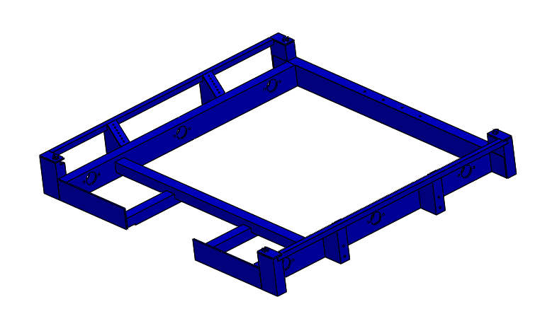
Drivebase
Today we nailed down an initial version of our drivebase which included the weldment, electronics baseplate, gearbox, and wheels. To finalize our design, changes may have to be made to the frame dimensions to accommodate both the ball and gear intake as well as the bumpers. Moving forward, our priorities are to pocket the baseplate and waterjet it out of 1/8" aluminum to save weight, design new mounting provisions/supports for the bumper rails for easy access, and potentially modify the main breaker placement which is currently positioned in the bumper rail.
Climber
After mounting the “comb” onto a shaft, we were ready to begin putting together the climbing prototype. However, we soon ran into some problems with the VersaPlanetary gearbox we constructed. After taking it apart and putting it back together (with a 10:1 gear ratio), we were ready to restart testing. At this point we ran into another problem as our setup proved to be unstable, making it impossible for the prototype to run smoothly.. We lasercut new, larger sidepanels and attached them to a 2×4 for stability. Next, we recut the metal bar we had used to stop it from interfering from the turning of the comb. Finally, we were ready to attach it to Dropshot’s drivebase, set up a hanging station, and start testing. While the prototype could successfully grab and hold onto the rope, it just did not have enough power to life the entire robot (even after changing to a 50:1 gear ratio in the VersaPlanetary). Looking toward the next build, we’ll have to find a way to increase the prototypes strength and speed.
Full Robot Mockup
The team created a quick mock up of the robot that features an intake on the front and shooter in the back. A large hopper made of polycarbonate pops out to over the bumpers to maximize its volume. A system of polycord or belts pulls the balls to the back of the robot then up into the shooter. It not a finalized design but serves as a start to get an idea of how much space subsystems like the bumpers and drivetrain take up so they can start being manufactured.
Programming
Robot Programming
Today, we fine-tuned a PID control loop for the intake. PID is a control algorithm that maintains a constant RPMs on a motor, regardless of motor loads. For example, a ball launcher’s motors may slow down when balls are inserted due to the increased load. PID would keep the motor’s RPM constant when a load like a ball is inserted.
We also rewired the encoders to connect to the RoboRIO instead of from the CAN Talon. At the moment, we are running our PID + feed forward loops off the RoboRIO (instead of the CAN Talon) and need the encoders to connect to the RoboRIO. While we can get encoder values from the CAN Talon, we need perfect time synchronization for the control loop on the RoboRIO, which we can accomplish by connecting the encoder to the RoboRIO.
Camera Connectivity
Today, we continued on the previous build’s progress, and decided to continue working on SPI. First, we connect the PixyCam to an Arduino and used the Arduino library to see if it worked correctly with the Arduino, as it hadn’t been working with the RoboRIO. Our test was successful, and the PixyCam worked as expected with the Arduino, leading us to conclude that there was a problem in the communication between the PixyCam and the RoboRIO. We connected the RoboRIO and Pixy pins to an oscilloscope to ensure that data was being transmitted correctly. After a few minutes of trying to get proper data, we realized that the PixyCam only broadcasted data when it saw an object; when no objects were detected, it would only send null bytes. This was the reason for the issues yesterday; when we got null bytes, we thought there was a communication error with the Pixy, as the documentation did not indicate that no data would be transferred when no objects were detected; we expected frame separators, but none were sent. After realizing this, we put a ball in front of the camera, which had been programmed to recognize balls, and updated our RoboRIO program to search for objects in a loop. At last, we were able to successfully retrieve object metadata, but we encountered connectivity issues between our driver station and the RoboRIO and were not able to finish our code. This build, we were able to get our program to parse the Pixy’s object broadcast data. Next build, we plan to finish our SPI driver by parsing the frame separator indicators, so we can recognize when there are multiple recognized objects in a single frame.
FRC Day 4 Build Blog
Day 4: Iteration of Prototypes
Prototyping
Double Wheel Vertical Flywheel
As we proved this flywheel could attain a high throughput, we transitioned today to begin testing different wheel types and compression as well as the conveyor system. In the process of setting up the next prototype, we found we lacked enough polycord pulleys, and machined more out of some delrin stock. We scavenged the 3:1 VersaPlanetary gearboxes from our previous prototype. While we did not have enough time to finish developing the prototype, we have all of the pieces and can finish it quickly tomorrow.
Fuel Intake
Taking the intake design from yesterday using two polyurethane rollers, we laser cut and assembled it, discovering that while it was able to pull balls up and over the bumper, the balls sometimes got stuck. the compression was too little on top of the bumper and it sometimes got stuck. The compression seemed to be too little at the top of the bumper because we didn't account for the bumper compressing alongside the ball, so we went back in CAD and redesigned the geometry of the upper roller to have increased compression. We are still in the assembly stage of the new and improved version, so we will see tomorrow how well it works with the improvements. For the future, we still have to see how effective the new design is before we CAD the real intake for the robot, but it is likely that this will be the preferred design because of the simplicity of having just 2 rollers.

Gear Intake
Throughout the course of the build today, we worked on constructing the 3D CAD design that one of the students made the day before. This worked out well because we were able to get the whole thing laser cut and fully constructed relatively quickly. Although this design seemed to be very similar to the previous version, a new key feature was added: A locking system for the claws while they are grabbing onto the gear. Although we were not able to fully test the design today, these improvements should theoretically allow us to manipulate the gear in 360 degrees, something we were not able to do previously. At the build tomorrow (Saturday), the main focus will be to finish building the prototype and look at potential ways of packaging the design give the tremendous size constraints presented.
Drivebase
Today we finalized the CAD Design for the Drive Gearbox, which is now almost ready for manufacturing. We started by pocketing the gearbox plates, a method used to reduce weight while maintaining the structural integrity of each plate. Our two gear ratios are 15:48 and 28:35. We decided to have a two stage gearbox with a dog shifter in anticipation of heavy defense, allowing the robot to have speed and maneuverability based on the situation. We also added spacers, an intermediate shaft, and designed a new front gearbox plate. Through the design of the gearbox plate, we were able to save 0.04 pounds in a game where the robot weight is inversely proportional to its speed.

Regarding the drivebase weldment, We modified it to have a cut out in the back. The gearboxes will sit in the two cutouts in the back corners and the gap in the middle will be for a gear intake mechanism..
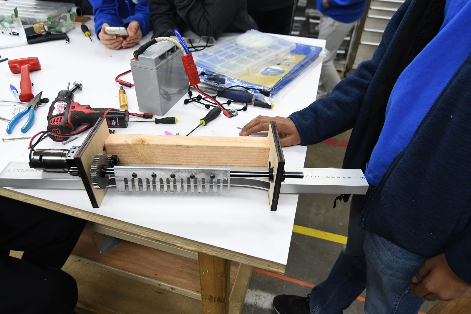
Climber
Today, the rope-climbing project finished prototyping a “comb” to grab the rope as well as housing to connect the comb to the robot for testing. We completed the comb by measuring the diameter of the string to find the distance between each prong of the comb. After this, we cut these parts out and tested it by ensuring that rope with knots would successfully hook onto the comb. Besides this, we also created the housing by attaching a VersaPlanetary enabled motor to a wood structure. We then connected the motor to a shaft by using gears and bearings. At this point, we just need to attach the comb to the shaft in order to finish assembly and begin testing.
Programming
Camera Calibration:
After manually calibrating one camera with limited success, we decided to automate the process to make calibration quicker and more accurate. The goal of the project is to have the OpenCV calibration code to read the camera input automatically so that we can see what angles will work for calibration before we take the picture. Today we downloaded all the necessary software needed to run the calibration program (OpenCV, Eclipse C/C++, MinGW, etc.); however, we did not finish this. Needed for next build is to set up Eclipse with a compiler and Download all the premade libraries for OpenCV. After that, we can edit the code to make it more user friendly, by having it connect directly to the Pixy Camera, and improve calibration.
Camera Connectivity:
Today, we deployed multiple test programs to an old RoboRIO to test our serial driver. Unfortunately, we ran into many issues early on. We then created another program to dump raw SPI input data to attempt to diagnose the issue: we noticed that we were only receiving null bytes (0x00), perhaps due to an SPI protocol error. We found that this occurred because the SPI connection hardware had a loose contact issue between the RoboRIO’s pins and the header pinout; after this was fixed, we received (0xff) bytes. Unfortunately, even after attempting to replicate the protocol according to the description, we could not get the PixyCam to send us anything other than (0xff), which was oddly not documented in the protocol information page. However, we suspected that the issue may stem from WPILib’s abstraction of the SPI interface itself; thus, we plan to implement a PixyCam SPI driver in C/C++ based on a low level library that accesses the serial port directly. In addition to working on SPI, we also worked on our `libpixyusb` interface, attempting to run the sample program. Unfortunately, we received an error about a failure to transmit/receive data over USB; we traced down the issue in the libpixyusb source code to the low level USB handshake. Getting `libpixyusb` to work reliably on the RoboRIO will likely be extremely difficult, possibly even requiring custom drivers and a kernel patch; the exact same code works as expected on an Intel x86 laptop, but when cross-compiled onto a RoboRIO with the FRC C/C++ toolchain, it encounters this unexpected error. After evaluating the pros and cons of both methods of connectivity, we decided to continue to pursue SPI rather than USB.
Robot Programming
Last workday, we tried deploying robot code to the RoboRIO but ran into problems deploying the code due to conflicting libraries for the CAN Talon motor controllers. After removing the conflicting drivers, we were able to successfully deploy the robot code. These changes are reflected in the latest commit on Github.
We then successfully deployed the code for the shooter prototype to the RoboRIO, but faced problems with maintaining a constant RPM. We used a basic feed-forward controller, which should set a near-constant RPM, but we measured drastic fluctuations in the RPM. We hypothesize that this is because the encoder is returning data at a different rate than the robot is running, leading to discrepancies in the measured RPM. To fix this, we will try connecting the encoder directly to the RoboRIO’s digital inputs instead of to the CAN Talon.
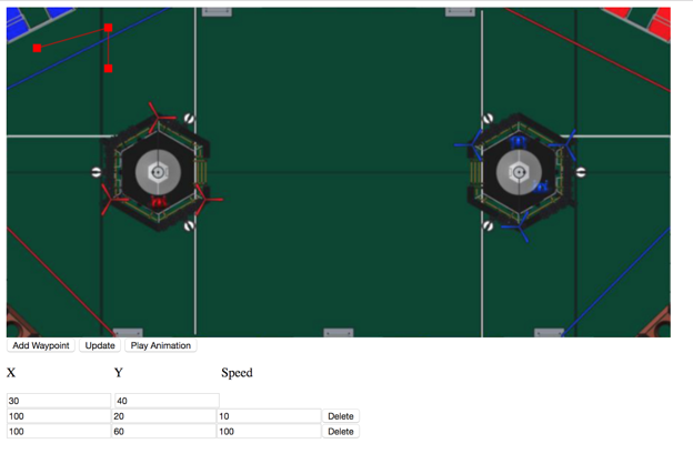
Waypoint visualizer:
We worked on an autonomous mode path simulator. The app lets a user enter waypoints and speeds and plots out a path that the robot will take. The app also supports animating the robot's movement. We also worked on implementing a radius feature into the program that would allow the robot to round corners. This app is a vast improvement over the current method of programming paths which require trial and error. With a helpful web interface, we will be better equipped to plan auto routines before we even test them, which allows us to develop before the robot is built. It’s not done yet, but we have made a lot of progress:
FRC Day 3 Build Blog
Day 3: Progress in Prototypes
Prototyping
Double Wheel Vertical Flywheel
Today, we worked on assembling the Double Wheel Vertical Flywheel. Taking the parts from last build, we assembled it using the new VersaPlanetary gearboxes and encoders we received. We assembled the flywheel to our previous spec, but we had problems with the gears we had in stock. We changed the ratio in CAD and laser cut a new plate. After doing so, we assembled the flywheel. While the flywheel worked well after changing to polyurethane, the conveyor system failed. Rather than cutting a new plate, we cut a bearing hole and inserted a hex shaft on the inside of the polycord, essentially acting as a tensioner. This worked relatively well, but needs further refinement. We did prove our concept, and will further iterate to better understand how best to integrate our design with the robot.
Testing:
For the Double Wheel Variable Compression Vertical Flywheel, we assembled the majority of the pieces and only need to insert the wheels to begin testing.
Fuel Intake
We finished assembly and began testing the belt intake, which was very fast when pulling balls in, but protruded several inches beyond the bumper. We began to design a new intake today, which will be much more compact and will therefore allow for a larger hopper and more room for other systems. This intake uses no belts, and two polyurethane rollers pull the balls up and over the bumper into the hopper. This removes the inefficiency and added complexity of belts, and makes the whole design cleaner and simpler. The intake's design is finished in CAD, but it has not been built or tested yet. On Friday we will laser cut it, finish assembly, and test it to see how effective it it..
Testing:
Gear Intake
The Gear Intake development process continued today with the construction of a recently CADed design that has an inner slider in order to pinch the gear between the claws and itself. This process was difficult because the .25” plyowood that was used for construction is actually .2”, so the original design needed to be modified slightly so that all the pieces would fit together. Other small improvements involved adding polyurethane strips to the inner slider and the claw so that the whole system grips onto the gear well.
Testing:
Drivebase
We finished an initial weldment of the general structure modeled after our 2014 robot and the side rails/bearings/housings modeled after our 2016 robot. Taking bumpers and an intake into account, the frame was dimensioned to fit within the 36" by 40" by 24” size limit.
In addition, we designed the drive train gearbox in CAD with 2 CIM motors per side in a 2 stage reduction with a dog shifter and pancake piston to have 2 speeds: low gear for pushing force and high gear for maneuverability. With the design almost done, we only have to add spacers, intermediate shaft, standoffs, screws and nuts, retaining screws, and pocketing to the CAD (members can access the design from pdm under the name 254-17-A-0300 Gearbox if you want to see or help design it).
Climber
Today, we designed and began to build prototype mechanisms for climbing the rope. The prototypes for actually holding onto the rope included variations combs with differing spacing. We began working on a standard mount for each type of prototype climbing roller. We decided to use a VersaPlanetary gearbox in our build, using a gear ratio of 1:90 to heavily reduce the rpm of the motors from ~18,000 RPM and increase torque to ensure the robot could lift itself. We then assembled the multi-stage gearbox, attached the motor, and soldered the battery leads. Lastly, we began the process of building a frame and prepared the parts to completely assemble the mounts next build.
Programming
Control Board
On Wednesday, we met up and worked on control systems for recent prototypes and we also continued developing pixycam communication. We added three talons to the prototype board to support the growing complexity of prototypes.
Robot Programming
With a prototype board ready, we added feed-forward PID control to our two-roller shooter prototype. PID is a control loop that keeps a constant motor speed, allowing us to effectively test the shooter prototype.
We also rewrote a majority of our code using elements from last year’s code, to avoid re-inventing the wheel. The new code is far more scalable and efficient. In particular, we implemented Loopers, a structure that runs code extremely fast, and compartmentalized our code into the various (potential) subsystems on the robot. We also discussed code conventions to ensure uniformity in the code down the road.
However, we had issues with compiling and deploying the code due to issues with the motor controller driver. We’re resolving those issues down the road.
Camera Connectivity
We worked on camera connectivity, finishing a testable version of an SPI driver built on WPILib for the RoboRIO. Previously, we built a native library that allowed us to communicate with the PixyCam over USB and wrote a JNI wrapper to let us invoke the native code from Java, but today we encountered issues when connecting to a physical PixyCam. Rather than debugging the USB connection, we decided to ensure that we could build a reliable SPI driver first, as we are confident that we will be able to communicate with the camera over SPI. Though a USB interface would be optimal, it is significantly complex and we plan to work on that functionality once the SPI driver is confirmed to work as expected.. We added a new pinout to the PixyCam and connected it to an old RoboRIO board for testing. To help with testing, we connected the PixyCam to a computer and trained it to recognize the yellow game balls. In the upcoming builds, we will proceed with testing our SPI driver with an old RoboRIO so we have a working method of connection for this year’s code.
FRC Day 2 Build Blog
Day 2: Prototyping
Today, we continued our work on prototyping designs for the shooter, intake, and drivebase. Our programming team also worked through a variety of projects including camera calibration and configuring the RoboRIOS.
Shooters
Double Wheel Horizontal Flywheel
We assembled the feeder for the horizontal flywheel shooter using three wheels of two different sizes to optimize contact with fuel balls. We determined that we would either use polycord or rollers for the feeder. However, due to availability of resources, however, we decided to prototype with a wheel roller. The horizontal flywheel was ready for testing but is still waiting on more planetary gearboxes.
Double Wheel Vertical Flywheel
Today we continued working on developing a double wheel vertical flywheel. In the process, we tried to optimize throughput with the limited space available on the robot. Initially starting with a hand loaded prototype, we combined the shooter with a conveyor prototype to remove the variables of human error.. We managed to design and laser cut the sidepanels for the prototype, and began assembly. We have organized the VEX Pro VersaPlanetary gearboxes and will implement it on Wednesday.
Another project based off a double wheel vertical flywheel aimed to optimize the best materials and fuel compression to maximize accuracy and shot speed. We spent the build designing a model in Solidworks to later be laser cut.. By the end of build, we acquired all the materials for the prototype including the 80/20 Extrusion Material, T-nuts, modified Versa Side Bearing Motor Gussets, 2 x 4 Wood Blocks, Bearings, and laser cut to design ½” Plywood.
Catapult
We improved the catapult and eventually hit an accuracy rate of 15/15 into the high goal. The improvements we made include:
-
Adding a stronger shaft
-
Tightening the medical tubing that provided the power to pull the shaft to the hard stop
-
Moving the hard stop and axle into the optimal position
-
Figuring out how to calibrate the machine
-
Securing the catapult to a piece of plywood so it wouldn’t move after every shot.
The design still needs a lot of improvements based on the power applied and the contact with the ball to make it into the boiler quickly and consistently.
Testing:
Intake
Today we took the intake prototype from yesterday and added several more surgical tubing belts in order to pull in more balls at once. In addition, we resized it for better geometry and added a CIM motor for lots of power. The results are very successful, and we are able to rapidly suck in several balls at once over a bumper, meeting our original goal for this prototype. The next step is to mount it on our practice drivebase and see how well it can intake once in a robot. We prototyped this specific intake because we have used similar ones in the past successfully, but were unsure how they would react to the plastic balls compared to more traditional foam balls.
Testing:
Drivebase
Today for the 2015 Deadlift drivebase we installed a new radio with updated 2017 firmware in order to successfully connect to the driver station. Additionally we experimented with different types of wheels. Initially we started with colson wheels on the outside and an omni-wheel for turning. The idea was that due to the center drop of the drivebase we would only be on an omni, and a colson wheel at all times. In order to optimize for turning we changed to all omni wheels, yet the turning was erratic so we think another set of wheels would be best for this game.
Gear Intake
Today we worked on the gear intake for the 2017 FRC Robot. The process involved spending a little bit of time on CAD to create a preliminary design, and then following up by actually laser cutting the wood pieces and then putting them all together. After that, we experimented with different heights for the grabber pieces on the claw to figure out which angle would be optimal in sliding up and over the edge of the gear. The next step in this project will be to cad a significantly more robust version of a similar design, as well as add a system for actually “grabbing on” to the gear so that we can manipulate it.
Testing:
Programming
A lot got done in programming today! We had our first build meeting and we will be having subsequent meetings every build where we will get anyone involved who wants to work on something. During this build we divided the work into the following tasks:
-
Installing updates onto drivers stations
-
Camera USB to RoboRIO Communication
-
Camera Calibration
-
Programming prototype boards
Driver Stations
We successfully updated the driver station software on the driver station computers. Now, everything works well.
Camera USB to RoboRIO Communication
Since last build, we successfully cross-compiled libpixyusb to the RoboRIO’s ARM architecture using QEMU on Ubuntu. We then created a JNI for it so that we can integrate it into our codebase. However, it has not been tested yet and we will be doing this throughout the week. If his port works, then we will not be using SPI with the Pixy Camera
Camera Calibration
The goal of calibration is to get rid of the distortion in the camera. Here are some screenshots that illustrate this distortion:
After the calibration, the dots in the image or more linear and the edges of the dot grids are parallel. This is the result of the calibration:
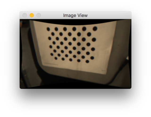
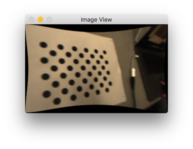
With better calibration, we will be able to more accurately approximate the angles of the goals so that we can make the targets. The calibration above isn’t perfect, but we are still working on making it better. The current issues that we have encountered are mostly due to the low resolution of the pixy camera which prevents OpenCV from recognizing the dots at more oblique capture angles. If it were higher resolution, it would generate a more accurate calibration.
Robot Programming
This build, we successfully configured the RoboRIOs and programming computers to use the latest version of FRC software, albeit with a few hiccups. In techno-speak, the RoboRIO wasn't assigning itself a static IP address, leading to communications problems. The programming subteam was able to overcome this issue, albeit with a temporary fix.
FRC Day 1 Build Blog
Day 1: Kickoff & Testing
Today was the first day of the FRC build season. The new game, FIRST Steamworks, was revealed, and we began evaluating strategies and testing prototype mechanisms for our 2017 robot.
Helpful Links
The game manual and rules are linked below. All team members should familiarize themselves with the manual, especially the Match, Game and Robot sections.
Game animation:
Prioritization & Strategy
To evaluate potential strategies for our team, we estimated times to perform tasks such as picking up and depositing gears, collecting balls, hitting hoppers, etc. We then compared that time to the point value of each task to determine a priority list of items to prototype as well as to begin match strategy.
For 2 strong robots working together in eliminations, an optimal strategy could be to each perform a 2 gear autonomous and then in teleop do 2 “hybrid cycles” in which they each score both a round of 100 balls and a gear followed by 2 “ball cycles” where they score only balls. This would produce a maximum score (assuming 80% shot accuracy) of 410 points. Perhaps the third robot could play defense rather than contributing offensive points.
More information on this strategic analysis can be found in this spreadsheet.
Prototyping
Today, we started by prototyping various mechanisms to accomplish each of the tasks in the game. Later, we will work to evaluate the prototypes, determine which are most promising, and integrate them together for more comprehensive testing.
Shooters
High Throughput Shooter –
We discussed creating a shooter which can shoot a large number of balls very quickly (goal is 50 in 1 second). This will need to be designed, built, and tested in the coming week.
Single Wheel Vertical Flywheel – back spin –
We made a prototype for the vertical flywheel by modifying the hood of dropshot. We found that the shots often were inconsistent depending on the orientation of the wiffle ball holes.
Testing:
Single Wheel Vertical Flywheel – front spin – We reversed dropshot and tilted it backwards to use the same flywheel but give the balls front spin instead of backspin. The balls still veered and had the same problem as backspin
Testing:
Double Wheel Horizontal Flywheel – This looks like the most promising prototype we have so far. It reduces spin on the ball to minimize the wiffle effect on trajectory. We are going to change this to a vertical double flywheel so that we can lengthen the wheel and shoot multiple balls side by side.
Testing:
Ball Intake – The preliminary plan is to have the bumper not at the limit of the maximum size so that we have room to deploy an intake in front of the robot (past the bumper, but within the maximum size). Although we could have a bumper gap, the maximum gap is about 14” and this setup would allow us to intake the full width of the robot which could be much faster and easier. It has been modeled in CAD and laser cut, but we have yet to assemble the prototype.
Catapult – A prototype was started for a spring-powered catapult shooter. This prototype needs some additional work to determine feasibility.
Gear Manipulation Mechanisms
Hook – We prototyped a one-way latch that is latches into one of the holes in the gear and then is pulled back into the robot to hold the gear with friction. This could then be actuated to tilt up and down to move from a floor-loading position to a hanging position. We made a new version with two hooks to allow for more misalignment when picking up the gears on the field.
Claw – A second prototype was built with two motorized wheels which intake the gear off the ground. The wheels are mounted to sprung arms which open around the gear as it moves in. It seems to work, but the quick prototype has the wheels spinning too quickly. We are going to work on slowing it down.
Drivebase – We have tentatively ruled out any sort of strafing drivebase because we don’t think it will be necessary. We will most likely use a 6-wheel or 4-wheel drive robot, as the team has high familiarity with these designs and should be able to construct them effectively and quickly. We are currently working on evaluating the best wheel configuration to have the ideal maneuverability by adapting Deadlift’s (2015 robot) drivebase with different wheels. We ran into some minor issues with radio connectivity, but we plan to fix this by using a newer radio. We need to finish the prototype.
Rope Climbing
Comb prototype – We discussed using a custom rope for hanging, likely a narrow, strong rope (like paracord) with knots. This prototype uses a comb-like hook to grab the knots and reel in the rope to pull up the robot and hang. We have tested it passively, but have yet to determine if it can support a robot’s weight.. There is still lots of work to be done, especially in optimizing the shape of the comb / spool so that the radius does not change too much as it rotates (necessary for gearing optimization).
Testing:
Programming
We started programming this season by creating a private code repository on Github based off what we did last year. We then started working on our demo boards, imaging them with the new 2017 firmware and installing driver station software to them. We also began experimenting with a Pixy camera for vision tracking. It seemed promising and easy to configure, but it didn't communicate easily with the roboRIO so more work is needed.
2016 FRC Championship
Overview
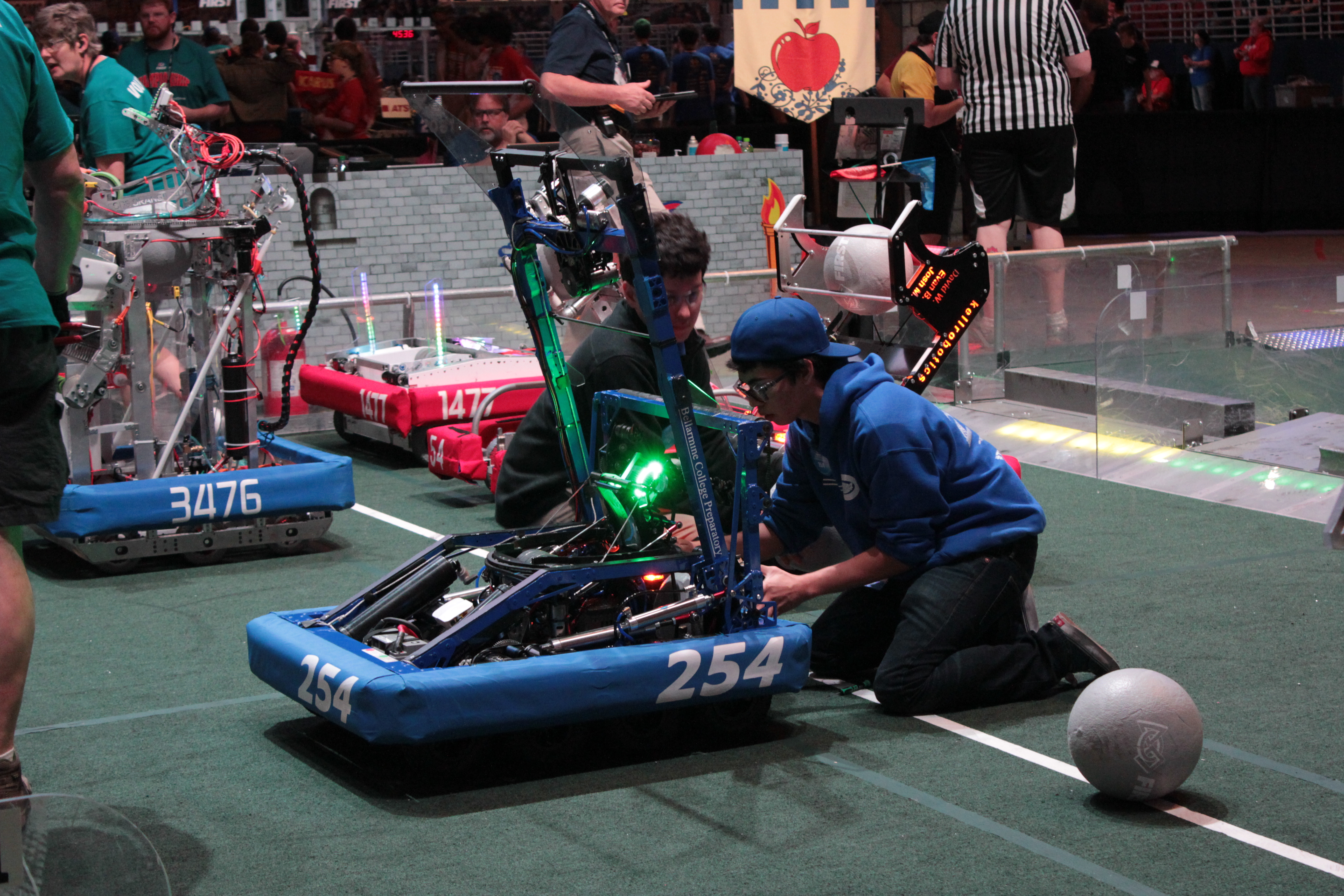
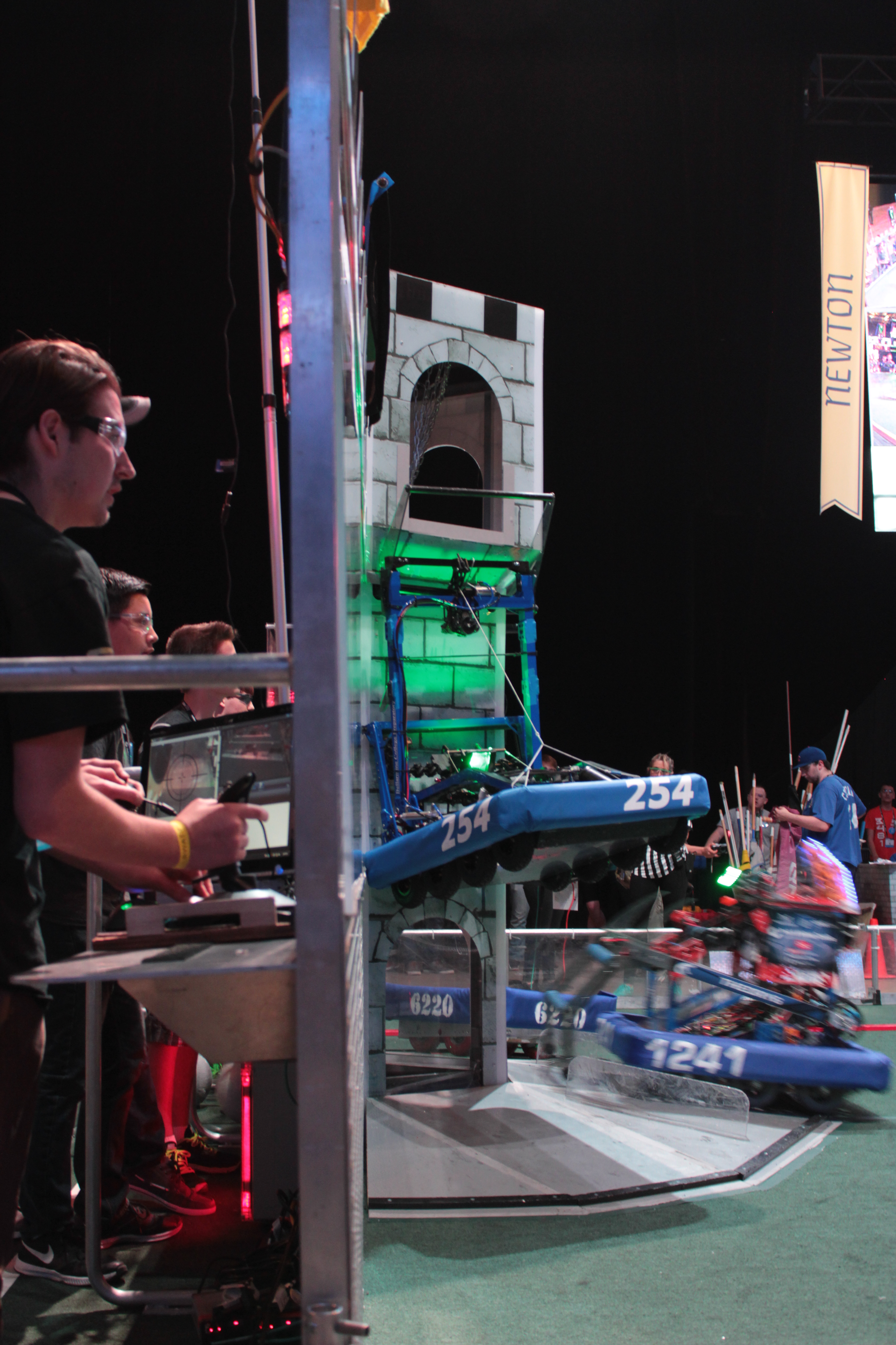
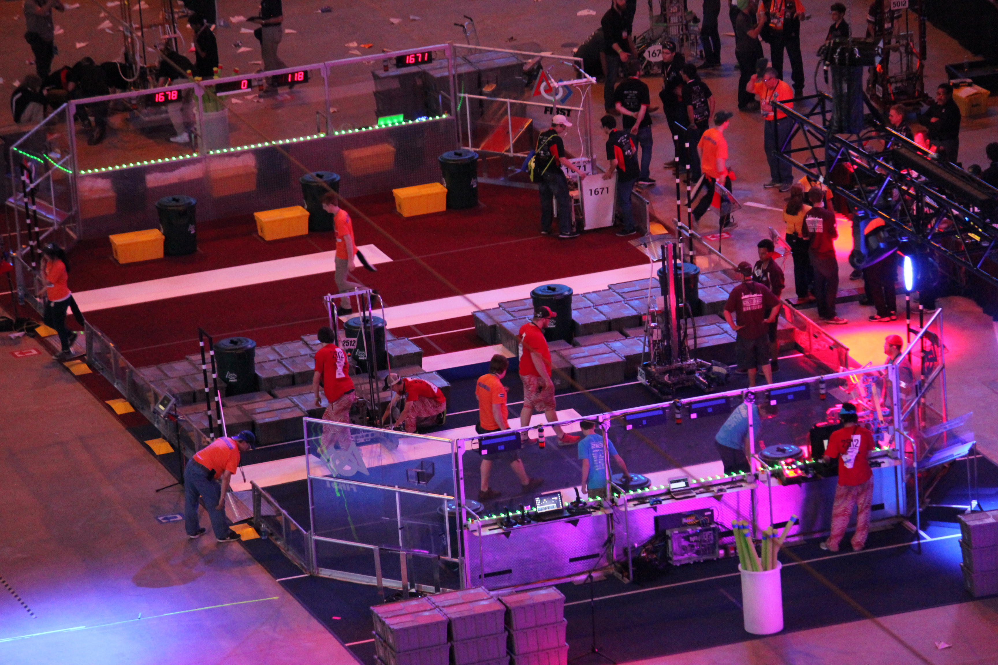
This past weekend, from Tuesday until Saturday, we participated in the FIRST Robotics Competition World Championships in Saint Louis, Missouri. On Tuesday, a smaller group of students left early to set up the pit and make sure everything would be set up for when the rest of the students arrived on Wednesday. We were placed into the Newton division, and with Team 1241, Team 1731, and Team 708 we played some great games in eliminations, but unfortunately were eliminated in the subdivision finals.
Qualifications
On Thursday and Friday, we played 10 qualification matches across both days, and earned 9 wins and 1 loss throughout those games. In qualification match 100, we even managed to push a disabled robot onto the batter, securing us an extra ranking point and winning us the game with a final score of 140-139. The qualifications overall went well for us, as we earned 35 ranking points and ended up as second seed going into eliminations.
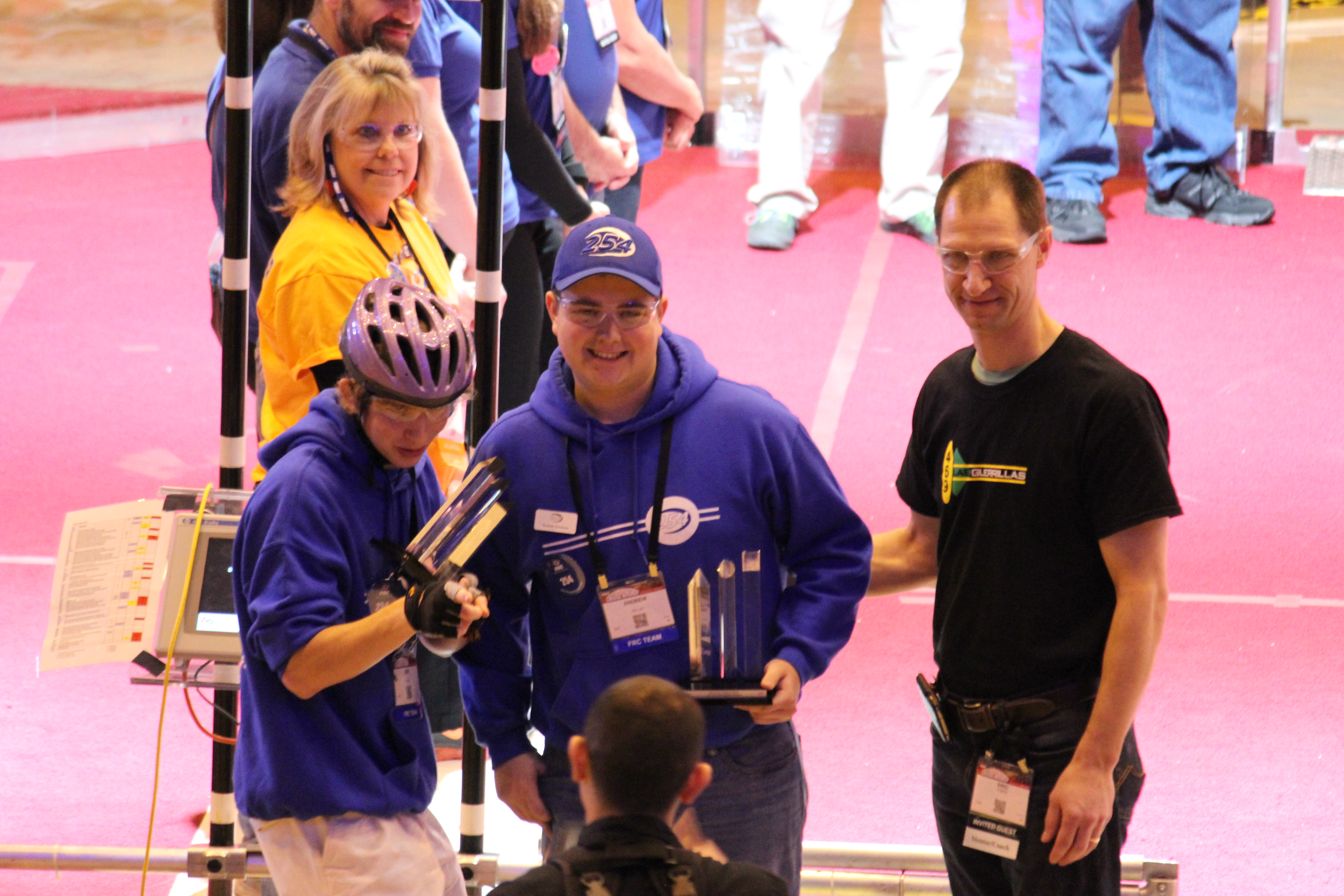
Eliminations, Einstein, and Awards
Saturday opened with the alliance selections, and we partnered up with the first seed team, Team 1241, Team 1731, and Team 708. With this alliance we hoped to consistently score highly while preventing the opposing alliance from having free reign on their side of the field. This strategy seemed to work out throughout our quarterfinal and semifinal games, with us scoring around 240 points in most of those games. In fact, we scored 254 points in our second semifinals game excluding foul points; however, a red card on our alliance prevented our score from being recorded that game. Moving into the finals, we matched up against an alliance including Team 217, Team 4678, Team 3476, and Team 188. Although we played hard, we were eliminated from the tournament in the Newton finals.
In the end, we would like to congratulate Team 330, Team 2481, Team 120, and Team 1086 for their success in winning the FIRST Robotics Competition World Championships. Additionally, we are proud of Team 987’s achievement in earning the Chairman’s Award, cementing them as a Hall of Fame team. Overall, we are extremely grateful to have had the opportunity to interact and play against many great teams at the Championships and hope to do even better next year.
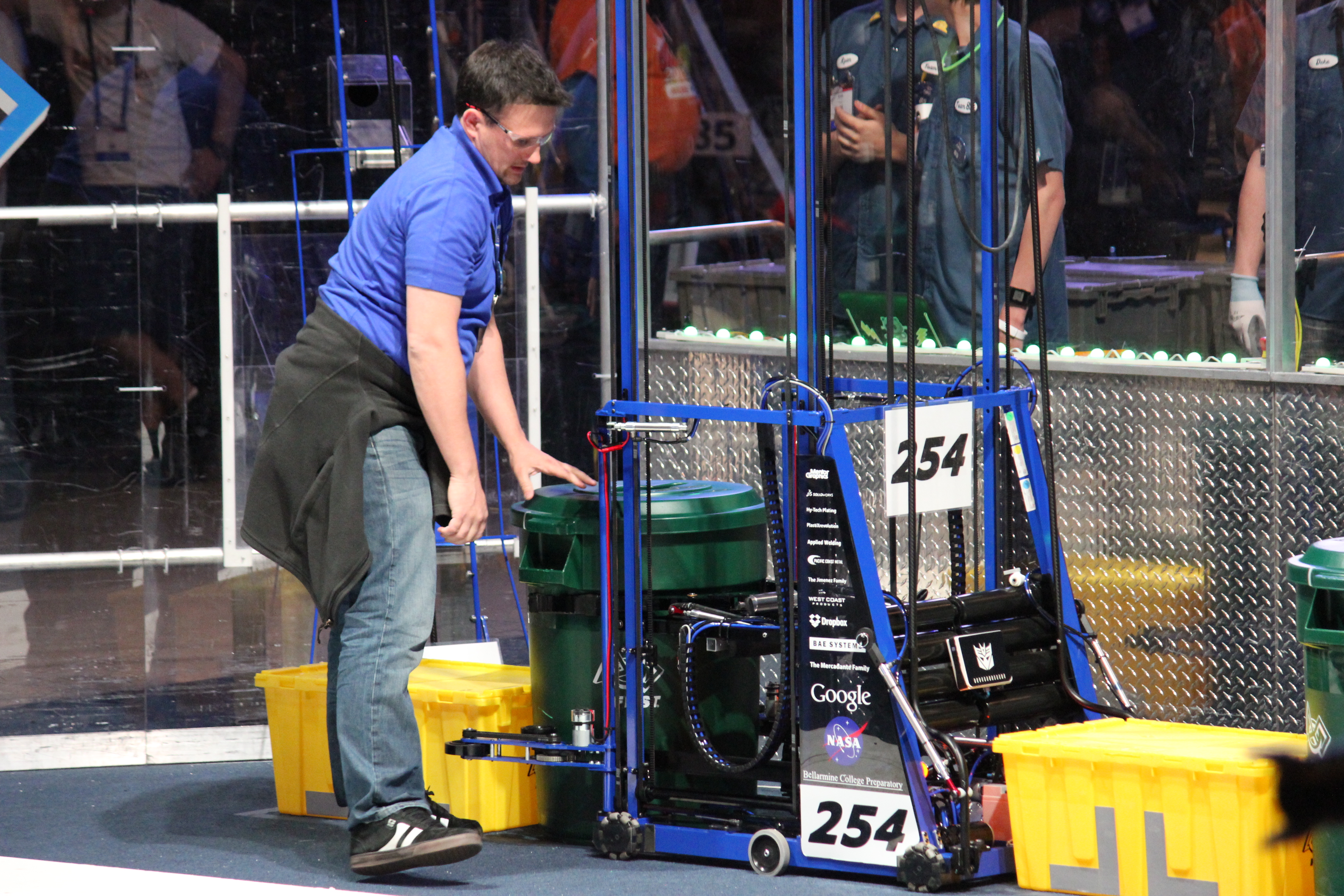
Dropshot Reveal
Team 254 proudly presents our 2016 entry into the FIRST Robotics Competition: Dropshot. Dropshot will be competing at the Central Valley Regional this weekend, followed by the Silicon Valley Regional and the last single FIRST Championship. More information on the robot.
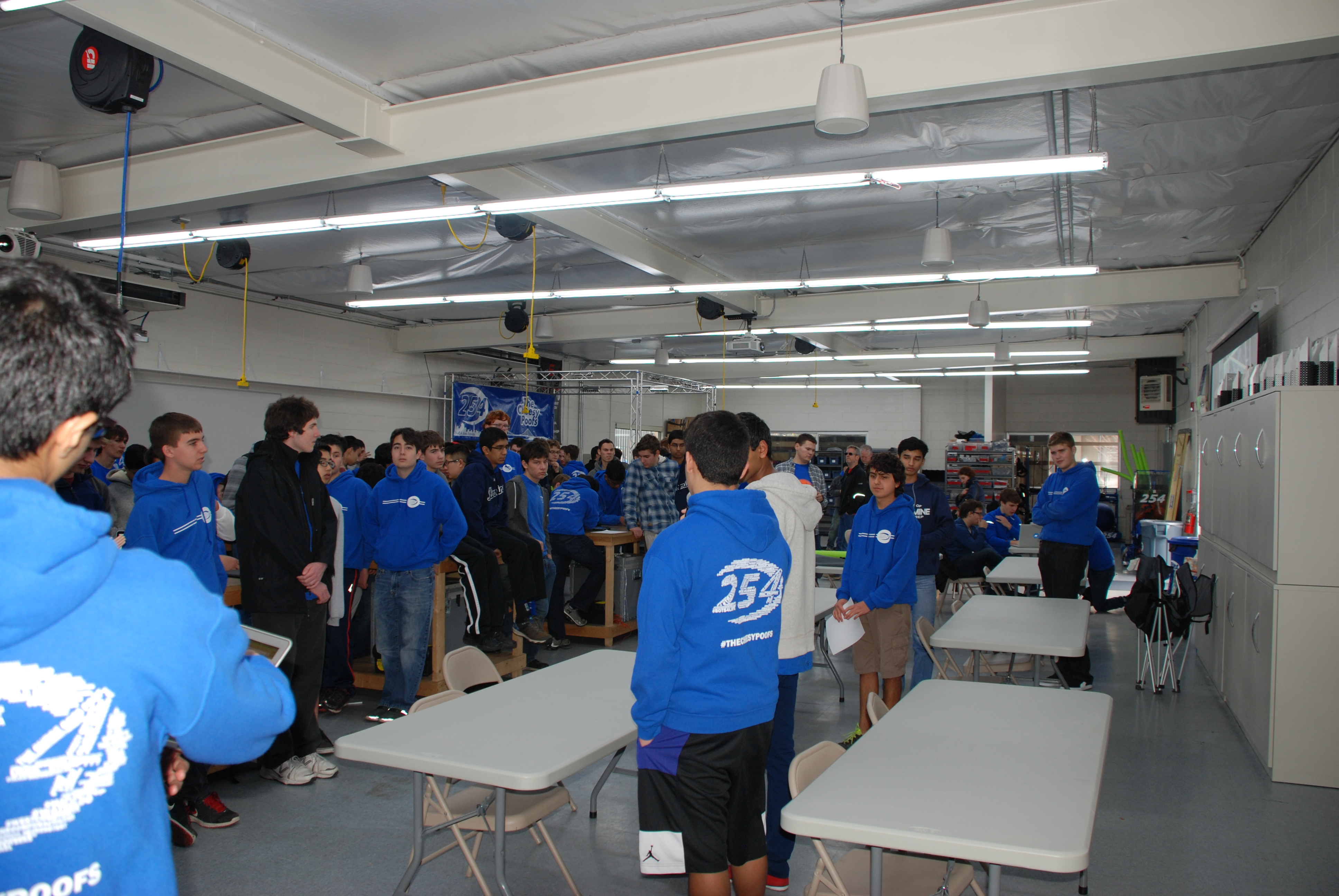
FRC Kickoff
This Saturday kicked off the first day of the 2016 FRC season with this year’s game, Stronghold. After the initial game reveal, both students and mentors gathered in the robotics lab to analyze this game’s rules and come up with strategies to tackle this year’s challenge. Once kickoff wrapped up around 4:00, the team began work on designing and prototyping parts of the robot.
2015 FRC Championship
Overview
With the increased size of the championship from 400 teams last year to just over 600 teams this year, 4 new divisions were added: Tesla, Carson, Carver, and Hopper. Team 254 was a member of the Carson division and ended up seeding first, picking teams 973, 999, and 4499, and then unfortunately experiencing some bad luck and being eliminated in divisional quarterfinals.
However, the team received the Industrial Design Award for their outstanding robot and had a great time in St. Louis on Sunday.
Qualification Rounds
The team played a total of 10 qualification matches on Thursday and Friday. Some matches were tough, but in others the team scored more than 240 points! By the end of Friday, 254 seeded first with a qualification average of 211.1, the highest of any team at the Championship, let alone any official FIRST event.
Here are some videos of our Qual matches, recorded by Team 1511: Rolling Thunder.
Qual 9: https://www.yo…v=JZOhJp0zlb8
Qual 22: https://www.yo…v=RW7emwjSH3I
Qual 35: https://www.yo…v=tT2bwv63cBk
Qual 47: https://www.yo…v=FUoWPrFWpI4
Qual 63: https://www.yo…v=gWIw4apFnLg
Qual 70: https://www.youtube.com/watch?v=\-Epkfyrgus8
Qual 83: https://www.youtube.com/watch?v=1IeSvV7UJxg
Qual 91: https://www.youtube.com/watch?v=UDrRzd2mqQ8
Qual 103: https://www.youtube.com/watch?v=9bTKW90O1MY
Qual 114: https://www.youtube.com/watch?v=HepI6GlEOQg
Awards, Alliance Selection, and Playoffs
The team received the Industrial Design Award. This award celebrates form and function in an efficiently designed machine that effectively addresses the game challenge. The judges were impressed with the robot’s ability to stack effectively both from the landfill and from the human player station by using a tethered ramp. This year, awards were shared between 2 divisions \(about 150 teams total\), so to receive the award was quiet prestigious!
During Alliance Selection, Team 254 selected Teams 973: The Greybots, 999: The MechaRams, and 4499: The Highlanders. The alliance was hoping to strike a powerful balance between stacking from both the landfill and human player stations and using fast can grabbers to ensure we would always be able to put up as many stacks as possible.
However, despite all of the alliance’s efforts, they were sadly eliminated in the quarterfinals. In their first match, buggy autonomous modes meant 254 was unable to get the 20pt tote stack. Then, after playing a nearly perfect match after that, Team 973 accidentally set down their last second stack on a noodle, causing that stack to fall over and domino another stack. Despite the terrible score, the alliance hoped that they could score at least 215 points in their second match to keep themselves qualified for the semi\-finals. Once again, however, 973 ran into 254 during auto, disrupting it and scattering the yellow totes in the way of the cans on the field. Then, after auto, Team 999 tipped over onto the landfill, blocking many of the totes 973 needed to make their stacks. It was an unfortunate series of events and bad luck and the whole alliance was bummed to have been knocked out so early.
However, the boys didn’t stay upset for long, we quickly ran around and helped our friends \(1114, 971, 1678\) competing in other divisions. We loaned batteries to 1114, and cheered on our friends on 1678 as they went on to win the entire World Championship.
Relaxing in St. Louis!
On Sunday, students got to choose to either wake up at 10am and go to the City Museum or sleep in and meet up with the others at the Arch at 1pm. It was a lot of fun and really relaxing to hang out and take photos under the Arch for an hour before heading to the airport.
Overall, FRC Worlds this year was one of the best in a long time. All the students had a ton of fun and no one was really bummed for that long. We’re excited to return and hoping to do better next year!
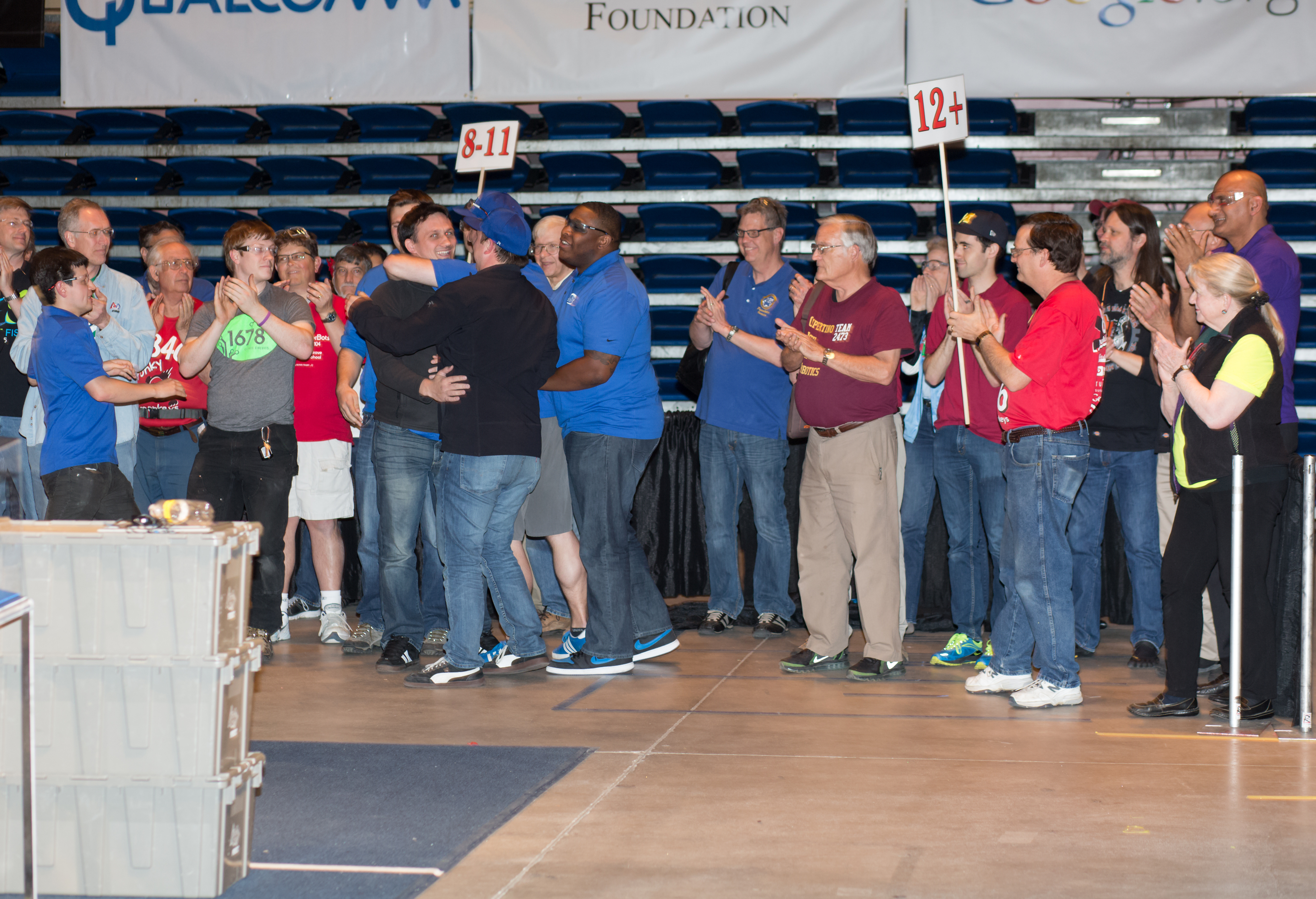
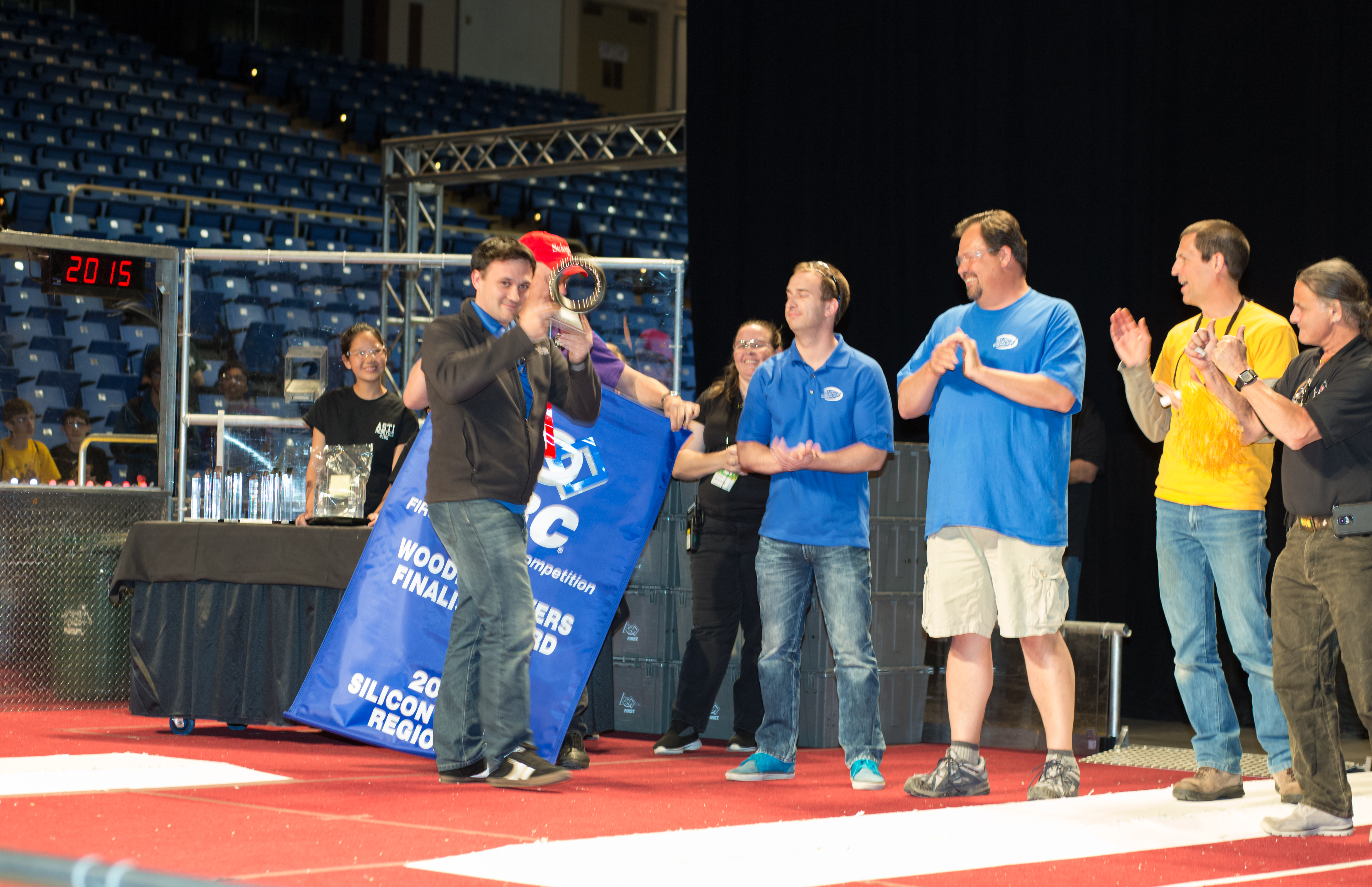
Woodie Flowers Finalist Award
This afternoon, Lead Mentor Travis Covington received the Woodie Flowers Finalist Award at the Silicon Valley Regional!
This prestigious award is given to only one mentor at each regional for that mentor’s ability to effectively communicate with and inspire students.
After nominating Travis for this award for many years in a row the entire team was so ecstatic to see someone so deserving finally get recognized. The students and mentors were cheering as if they had just won the World Championships again!
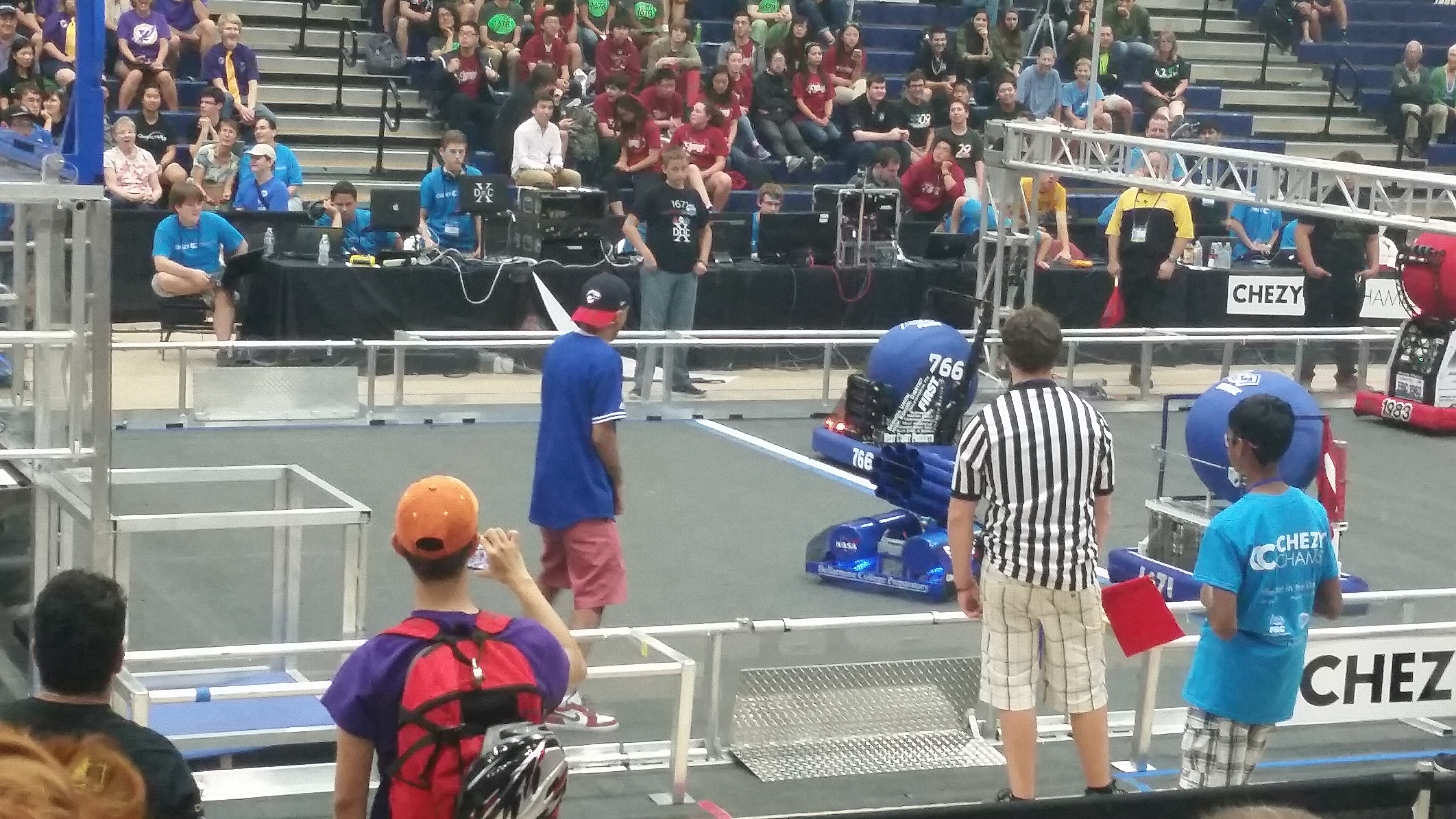
Chezy Champs: Behind the Scenes
Today teams from across the country gathered to compete in Team 254’s Chezy Champs Aerial Assist competition. After Friday’s hard work setting up the field and teams moving setting up their pits and robots, we’re ready to start a day of competition!
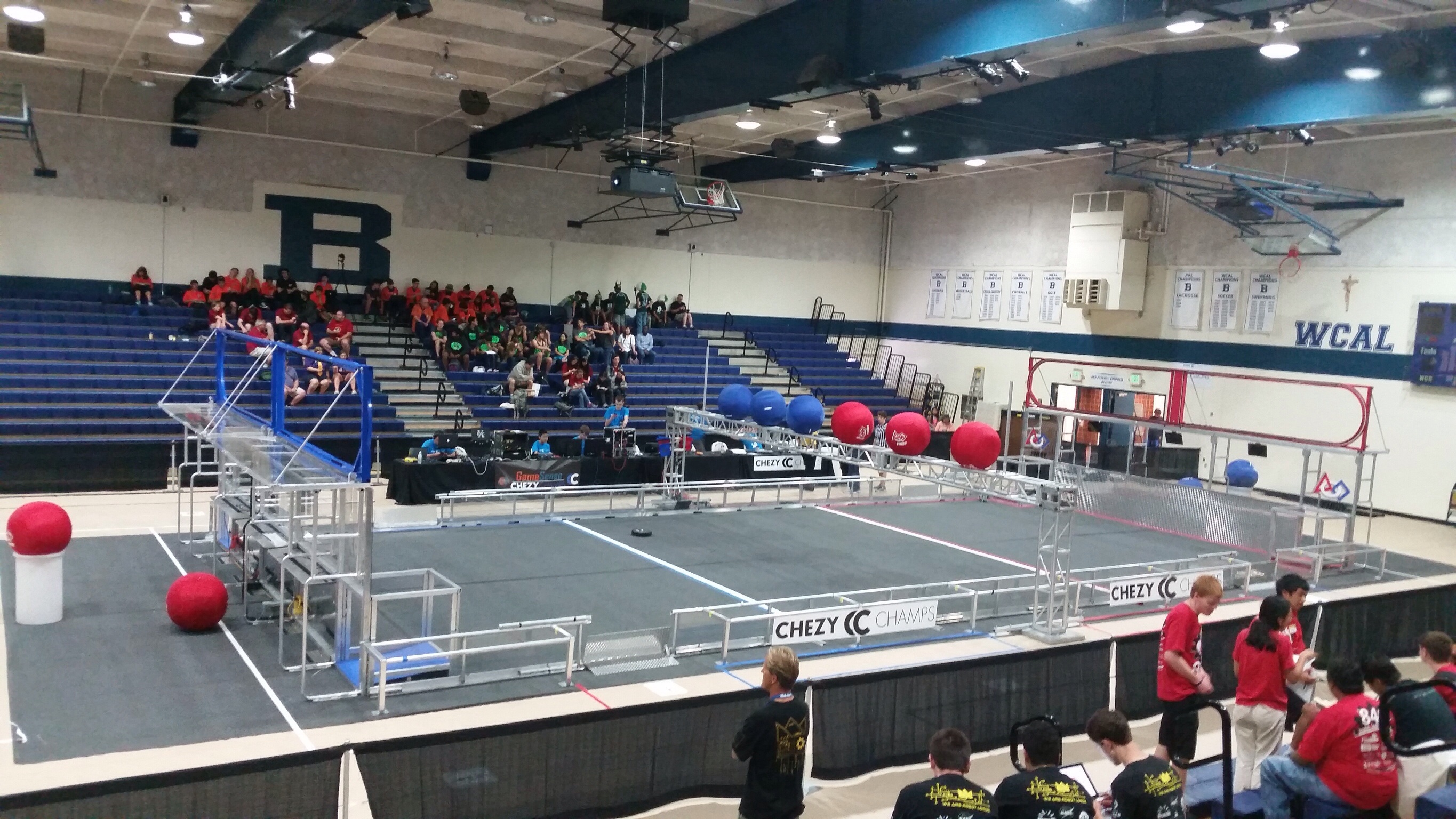
Pre competition hustle
I love the smell of robots in the morning. Starting at 8am this morning, teams were allowed into the pits to start modifying and preparing their robots, and teams entered the Bellarmine gymnasium to stake out spots in the bleachers. And about half an hour later Shockwave was released and tested in the field.
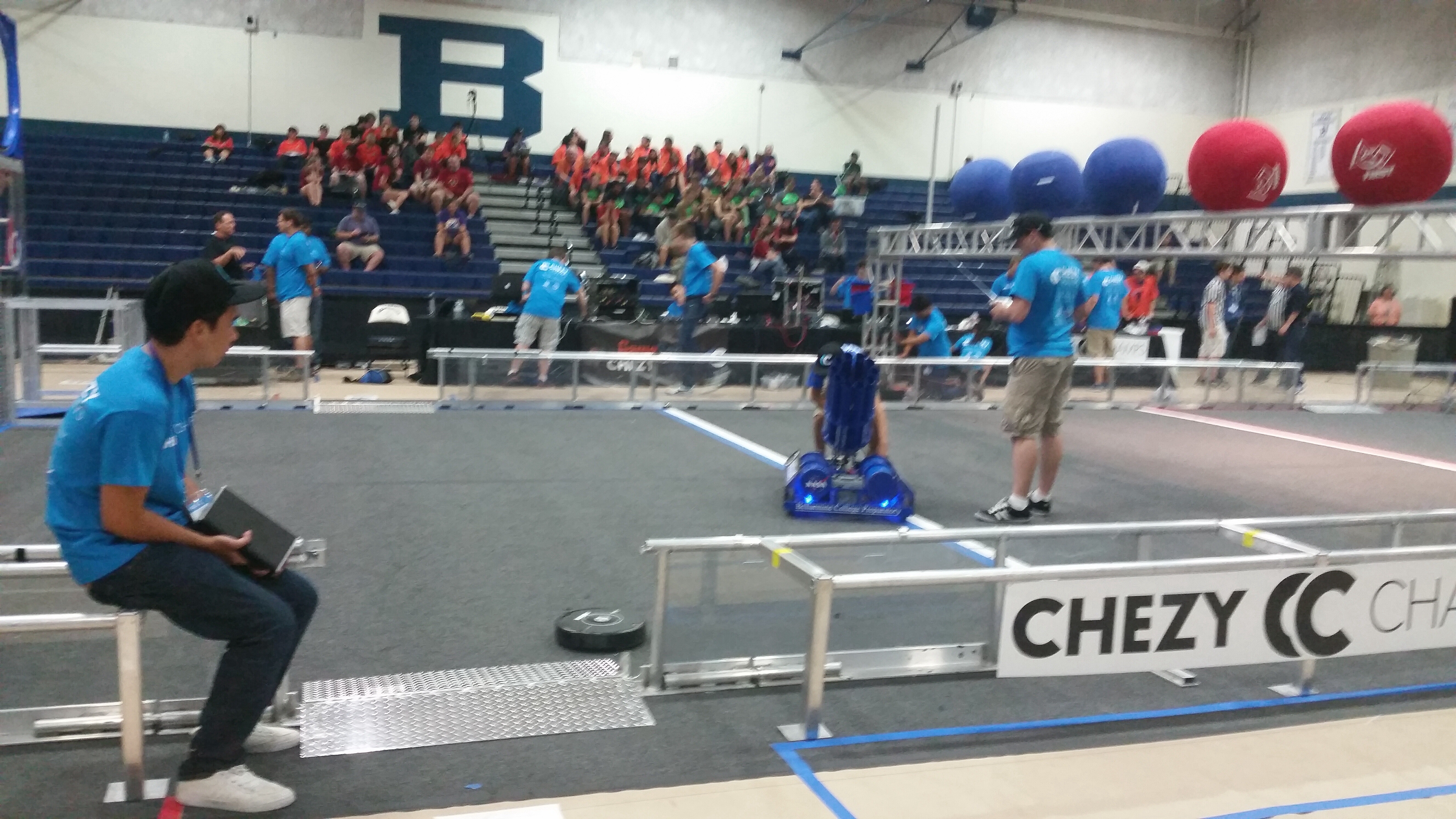
Shockwave showing off for the crowd
At 9:30 the opening ceremonies began, introducing our emcee and game announcer, Karthik Kanagasabapathy and Paul Copioli.
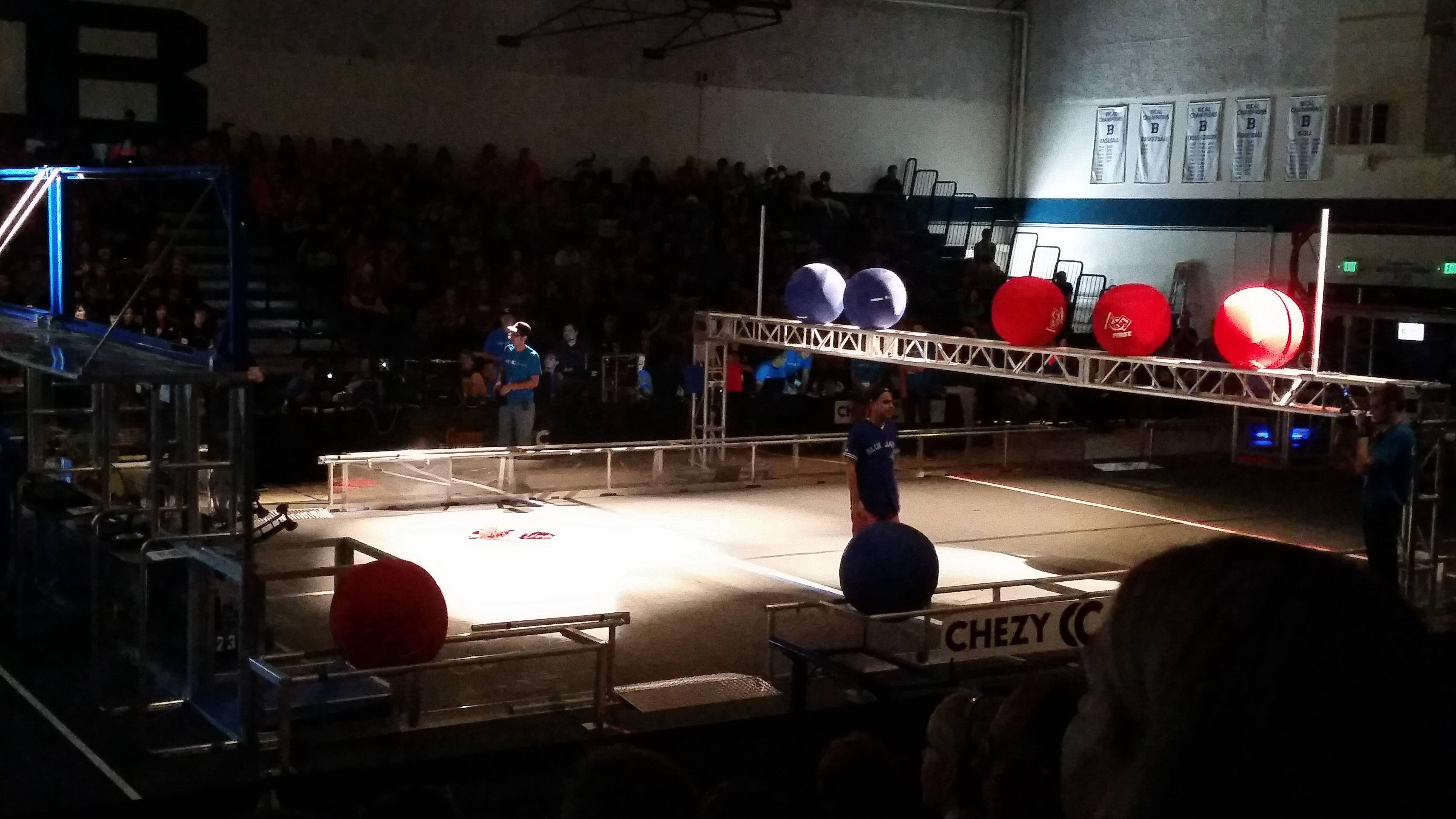
Pre game pump up
After all teams had staked out seats in the bleachers and the competing robots were in their ready position, at 10am the first match started!
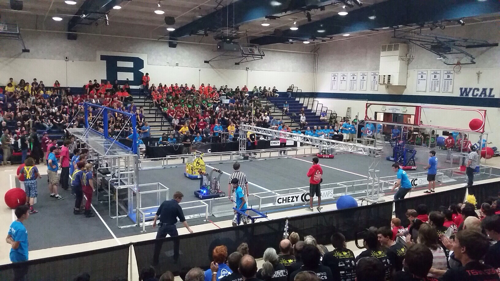
First match autonomous mode begins
After match 3 Shockwave decided to come out onto the field to compete with Karthick
SHOCKWAVE ON THE LOOSE!
After the first match I decided to take a walk around the facilities. Right behind the arena was the CC swag shop, where t-shirts, sunglasses and other swag were sold.
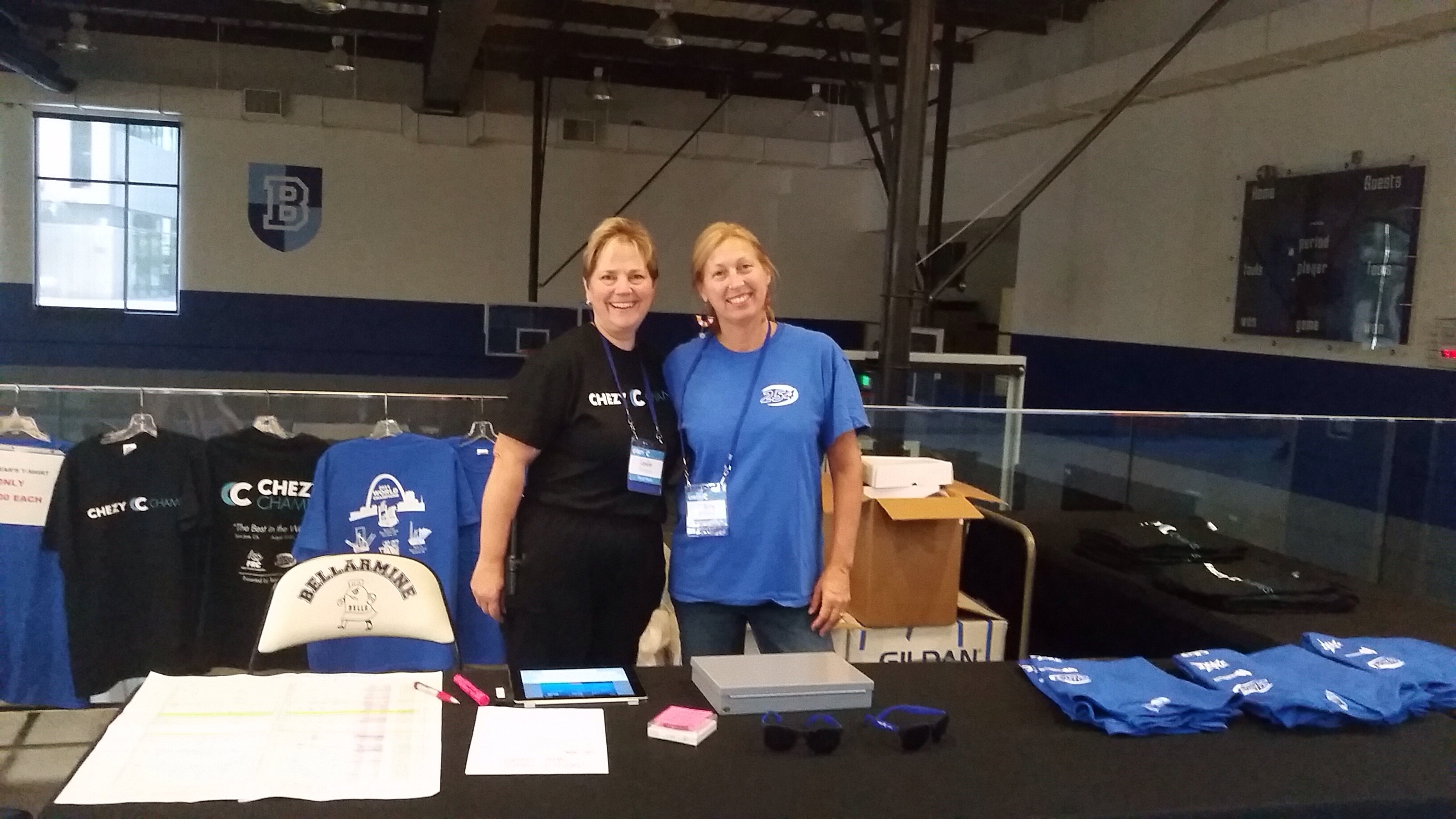
Two 254 moms manning the swag stand
I became aware that other items such as snap backs, volunteer shirts, and even life sized EJ faces (for the true EJ fans) were available through preorder.
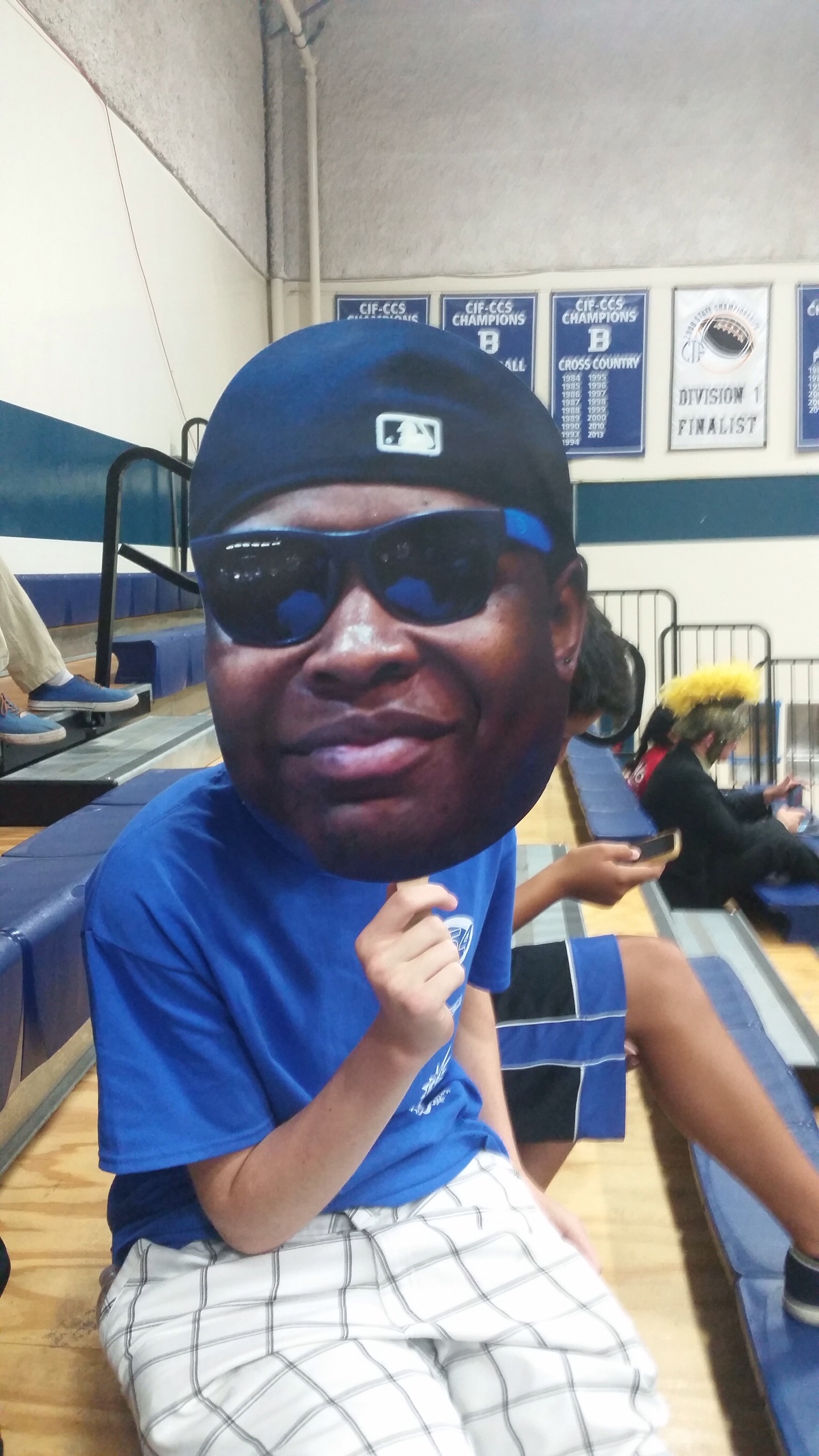
Team 254 member, Michael Ramstad, showing his pride with a life-sized EJ face
Next to the swag shop were the official Chezy Champs trophies, including the widely coveted golden corn dog for display of GP throughout the tournament.
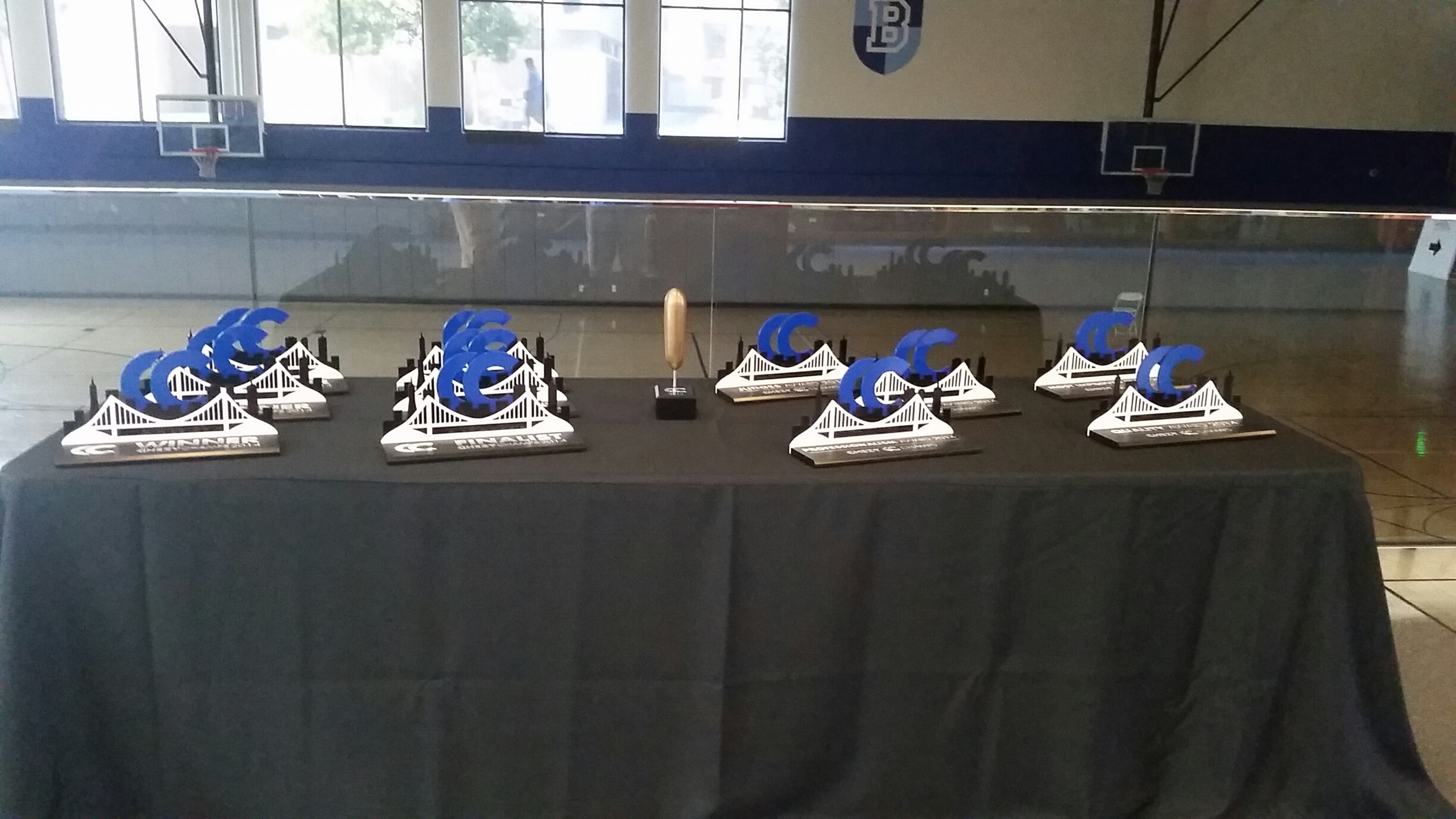
The glorious golden corn dog and other trophies
Lastly I headed out to the pit area in Liccardo to check out some of the other teams. At the admin desk, manned by 254’s glorious president Andrew Torrance, I checked in as a CC volunteer and put my super safety glasses on.
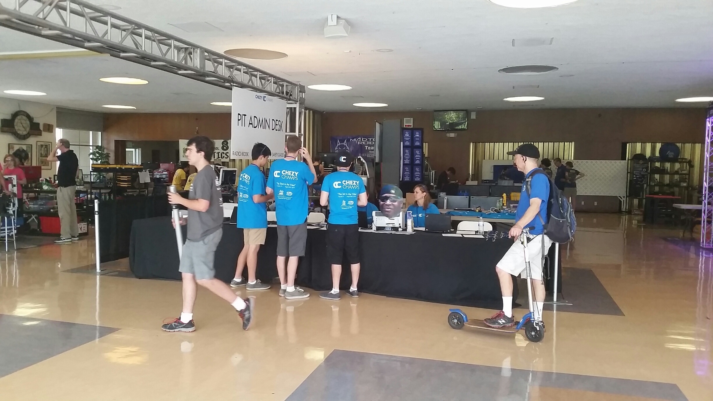
Staff surrounding our glorious student leader, Andrew Torrance
The first team I encountered in the pits was the Buchanan Bird Brains, Team 1671. A few members were willing to answer my questions about the tournament and their team:
Q: Where is your team based?
A: Our team is based in Clovis, California. It’s like the little brother of Fresno.
Q: What is the name of your robot?
A: The name of our robot is “Doc 10” because Doc Buchanan is the founder of our team’s high school and 10 because it’s team 1671’s tenth year competing.
Q: What does FRC mean to you?
A: FRC is like the family you never knew you had, and once you’re in the FRC family you never want to leave.
Q: What do you think of the Bellarmine campus?
A: The architecture is beautiful, it honestly looks like a college campus.
After interviewing the Bird Brains, I decided to talk to some of the teams at the other end of the pit. After a few minutes, I found that the Team 4201 pit was open for visitors!
Me (in the blue shirt) taking notes on my interview with a member of team 4201
Q: Where is your team based?
A: Our team is based in Hawthorne, California near L.A.
Q: What is the name of your robot?
A: The name if our robot is #straightflexin. The # is part of the name, too! And it can’t be spelled out.
Q: What does FRC mean to you?
A: Since our school doesn’t really have any sports teams, this is our school sport. Like I used to play hockey but there was no hockey team. And, FRC is like the engineering version of a varsity sport. So for me it became a substitute for playing on a team in high school. Really it’s just the best thing ever.
Q: What do you think of the campus?
A: The campus is awesome, we really love your copper pipes. The water is so clean!
Next interview was with Team 696, the Circuit Breakers:
Q: Where is your team based?
A: Our team is based in La Crescenta in L.A. county, a little bit north of L.A.
Q: What is the name of your robot?
A: The name of our robot is Snapdragon. We actually have two robots, the one we use to compete is named Snapdragon and the practice bot we call “Snapdragon upside-down.”
Q: What does FRC mean to you?
A: FRC is one big family, once you’re in it helps you to stay connected with people who share your interests.
Q: What do you think of the Bellarmine campus?
Oh this is a high school? I seriously thought we were at a college. Wow, it’s really big.
After interviewing Team 399 I decided to visit the local food trucks for lunch. Outside we had the food trucks “sticks” and “scoops,” and inside food vendors sold everything from muffins to pizza.
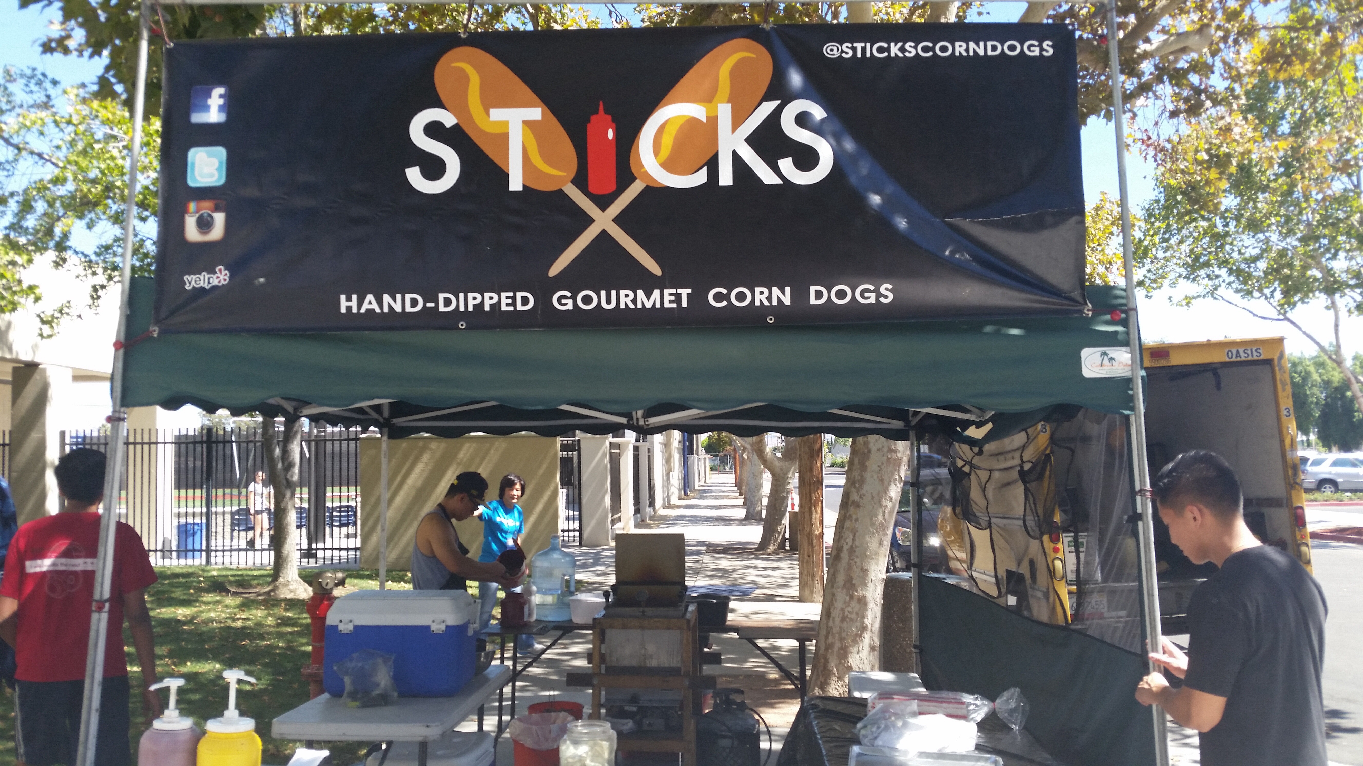
Jared must be so proud
After a short food break/nap in the field, I went back to the arena to make sure everything was ok. Everything was going very smoothly, and all the teams seemed to be enjoying themselves. None of our equipment was blowing up, there were no electrical fires, and none of the gaming servers crashed. I’d say that’s a success!
I had a lot of fun meeting and talking to all the different teams, and hope that the guest teams had just as much fun competing in and watching the matches as we did. Thank you to all the teams who showed up, and those who supported us by watching the event live on Twitch.
Go Poofs!
IRI 2014 Offseason Regional
IRI Competition
Everyone had a great time at IRI, reconnecting with old friends like 233, 1114, and 2056, meeting new people on different teams, and eating a lot of delicious corn! We went undefeated in our qualifying matches and seeded first, partially due to our powerhouse human player Brandon Wui with his “Jordan” throws into the robot. After choosing our alliance partners Team 1114: Simbotics, 330: The Beachbots, and 2013: Cybergnomes, we moved up the bracket all the way to the Finals, and after 2 very intense matches, we got second place! We were all very happy with our performance and very happy to have been able to attend IRI this year.
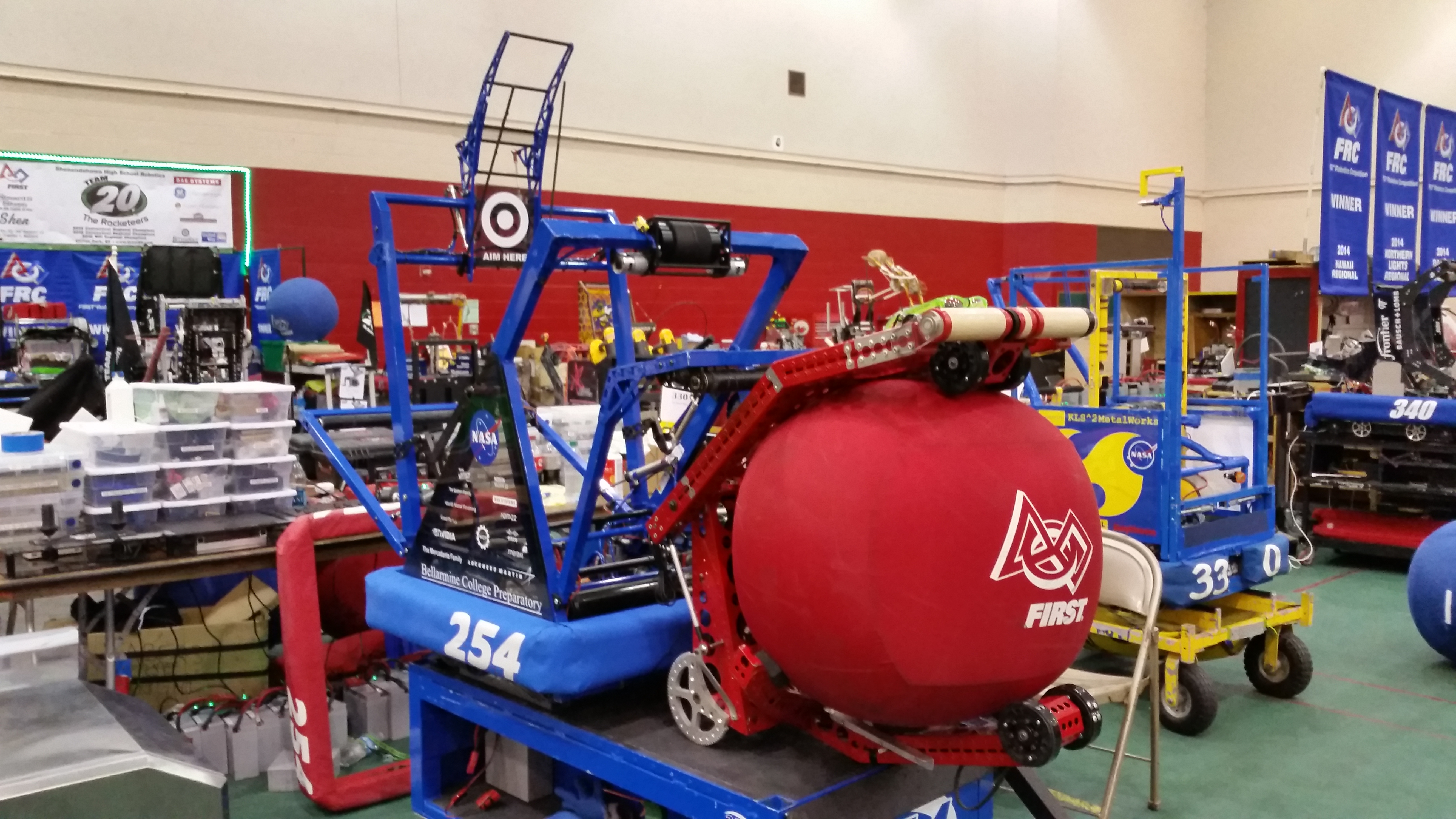
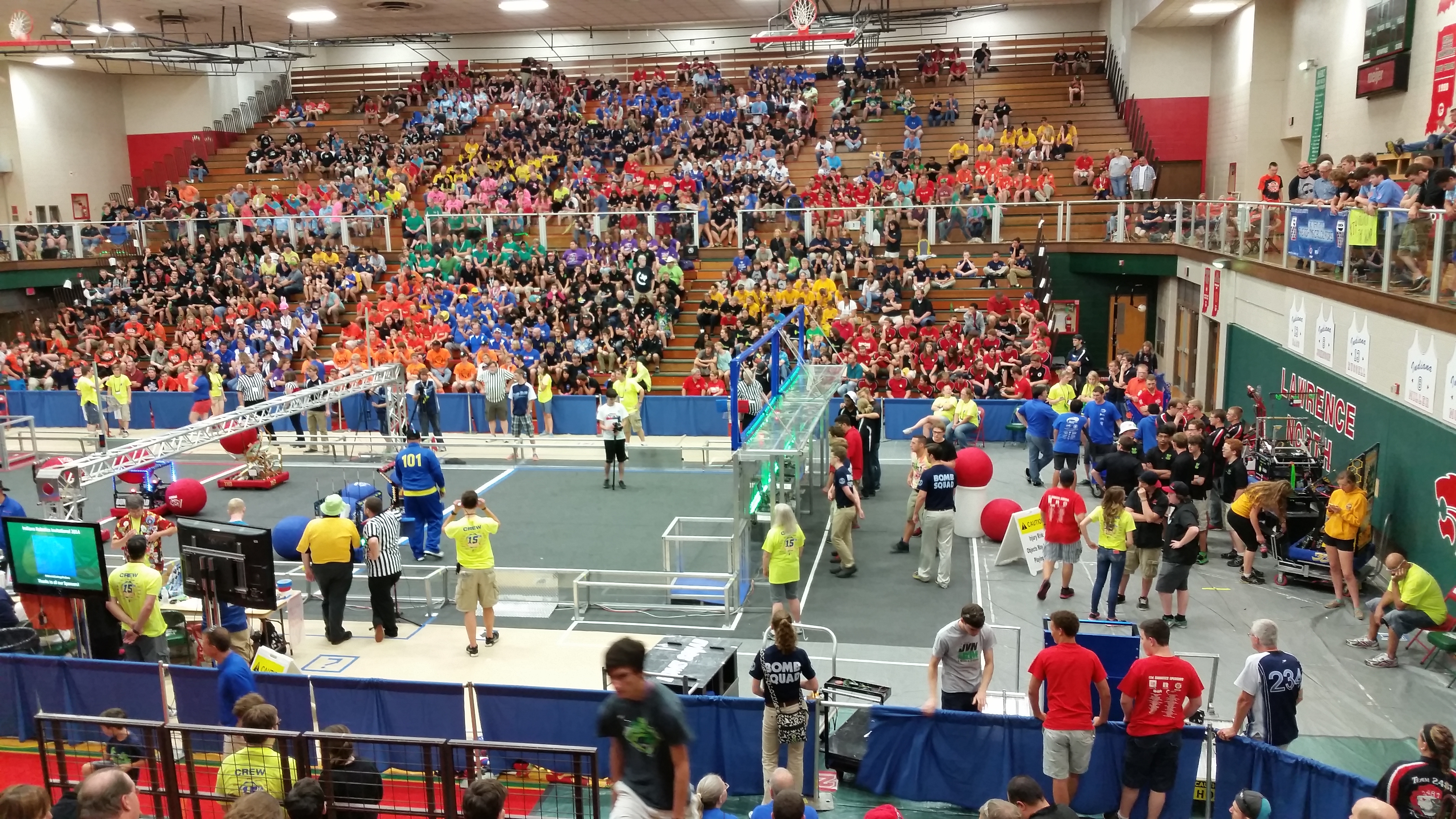
Fun in Chicago!
However, our adventures didn’t stop with IRI. After the very early first flight to Chicago, our connecting flight got cancelled. At first it looked like we’d be spending 12 hours wandering around Chicago airport, but the mentors decided to make it an adventuring day through the city of Chicago! We took the famous L train into downtown and had some fantastic Chicago style deep dish pizza at the world-famous Giordano’s Pizza. Next stop was the Bean in downtown Chicago, then finally we found a nice shady patch of grass in which both mentors and students took very needed naps, and some ended up with a little grass on their foreheads. Finally we made it back to the airport and on our plane home. Thank you to all of the teams and staff at IRI for making such a great competition and we hope to be able to go next year!