
Blog
FRC Day 32 Build Blog
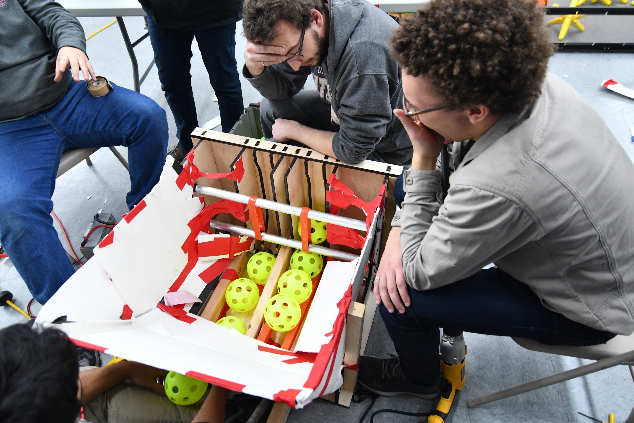
Day 32: Continued Assembly and Programming
Gear Grabber
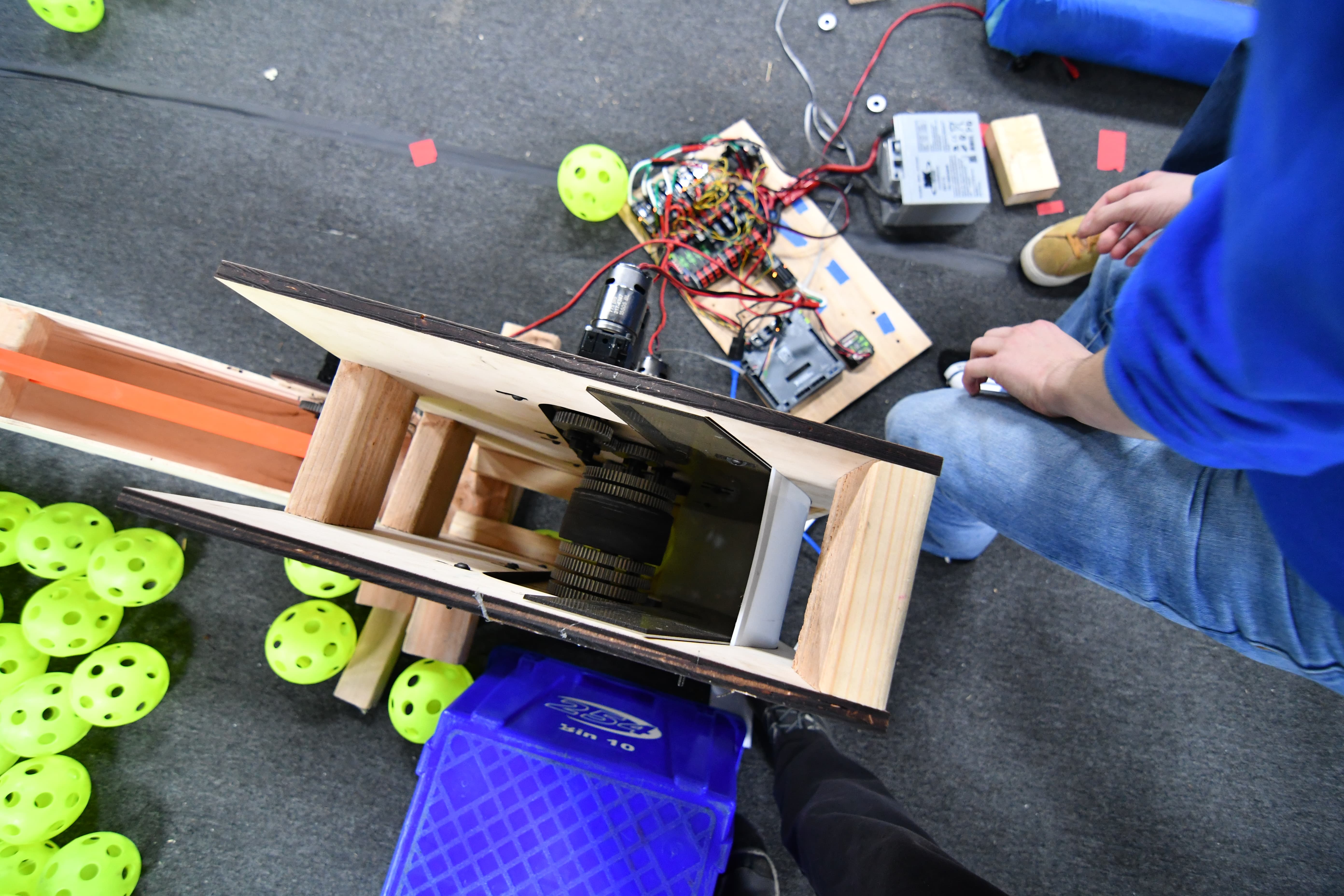
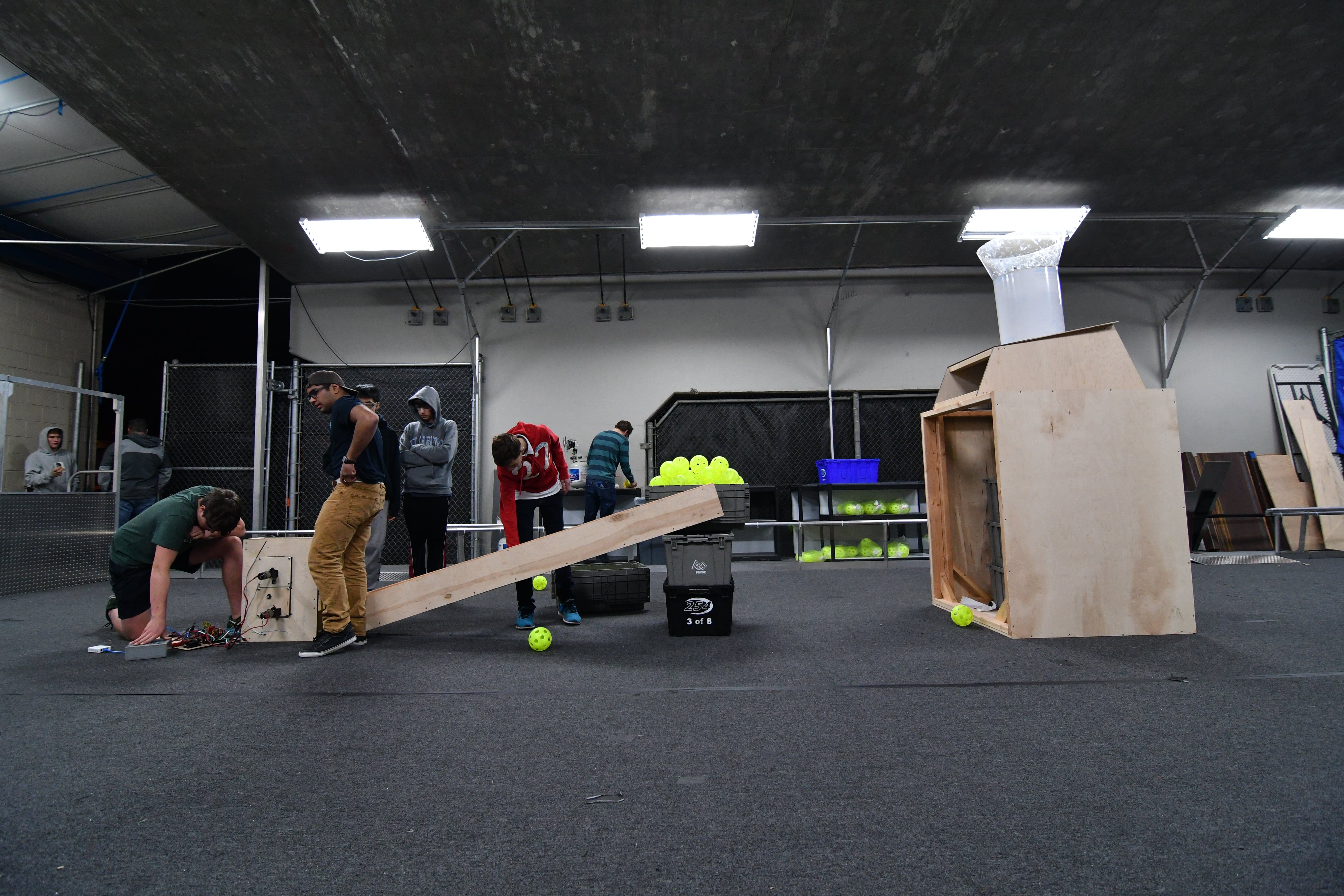
Today, we worked on designing and testing the roller gear grabber. We installed a prototype onto the programming robot, and it worked somewhat well. When we drove into a gear directly, it was always ours, but it was narrow and difficult to always aim correctly at the gear. We played around with passive funneling, but were unable to significantly improve the width from which we can intake because of the sidewalls of the rollers were too low. Griffin and Colin are currently designing a new gear grabber that will likely funnel more effectively, and we plan to have it on the robot and testing it on Friday.
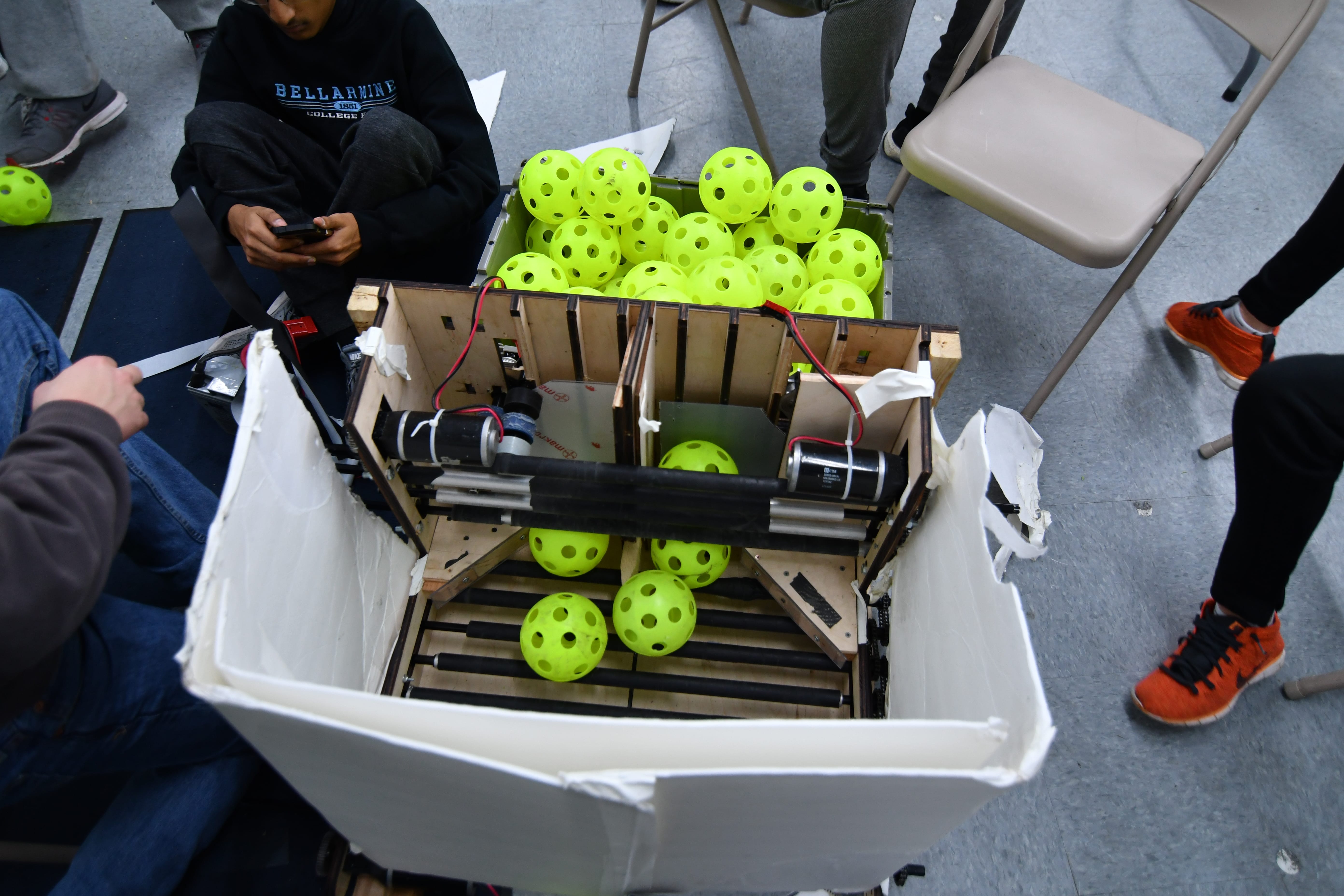
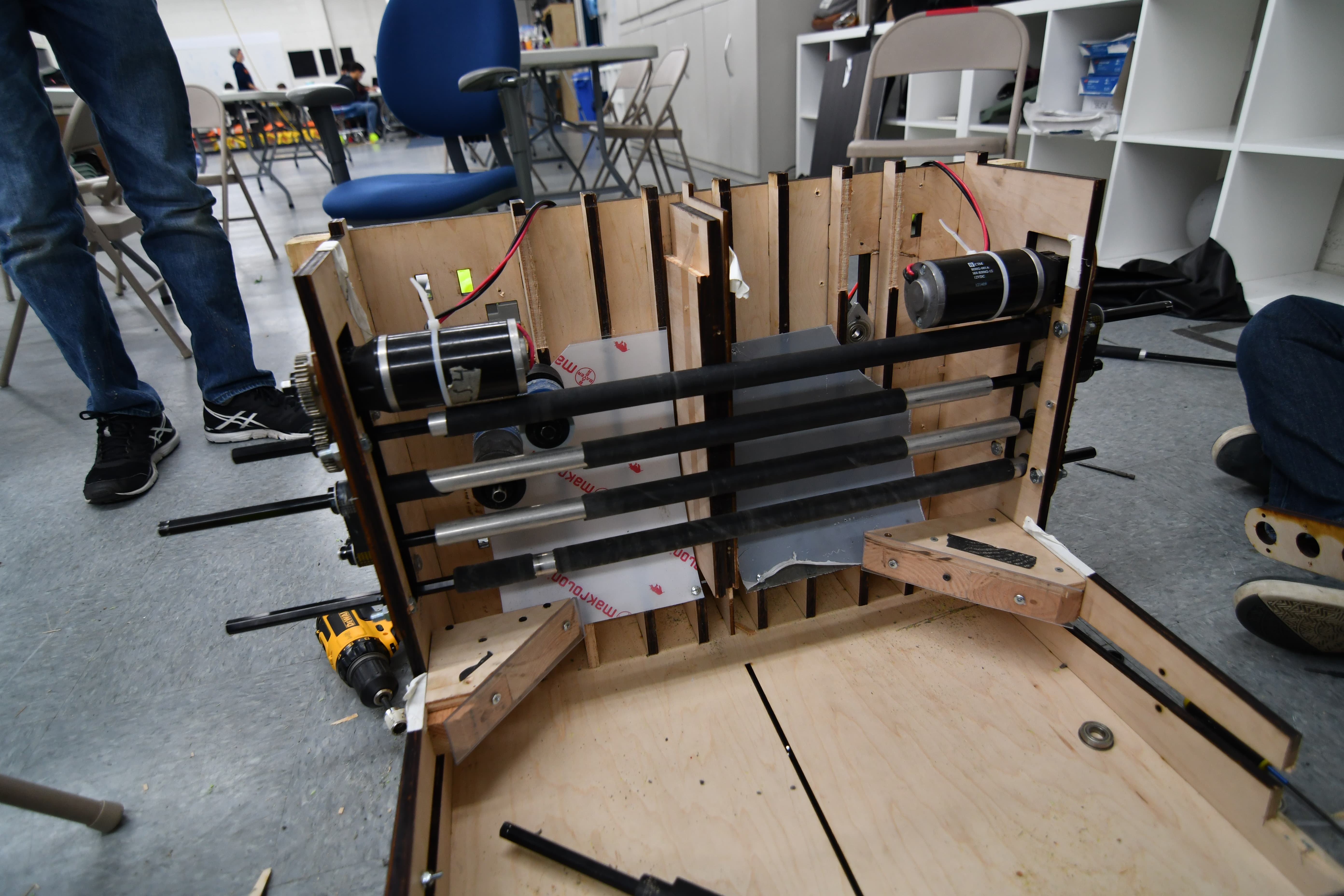
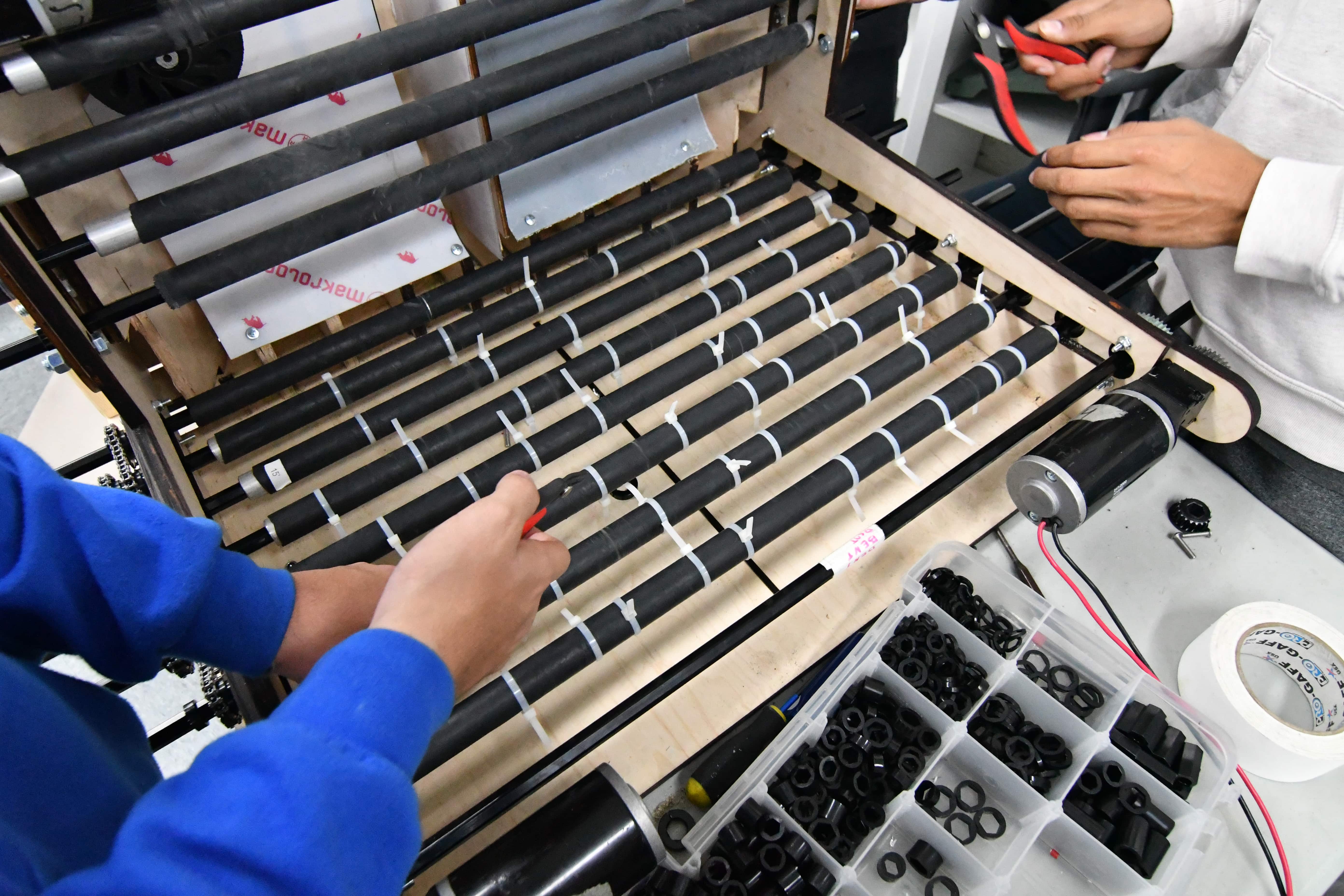
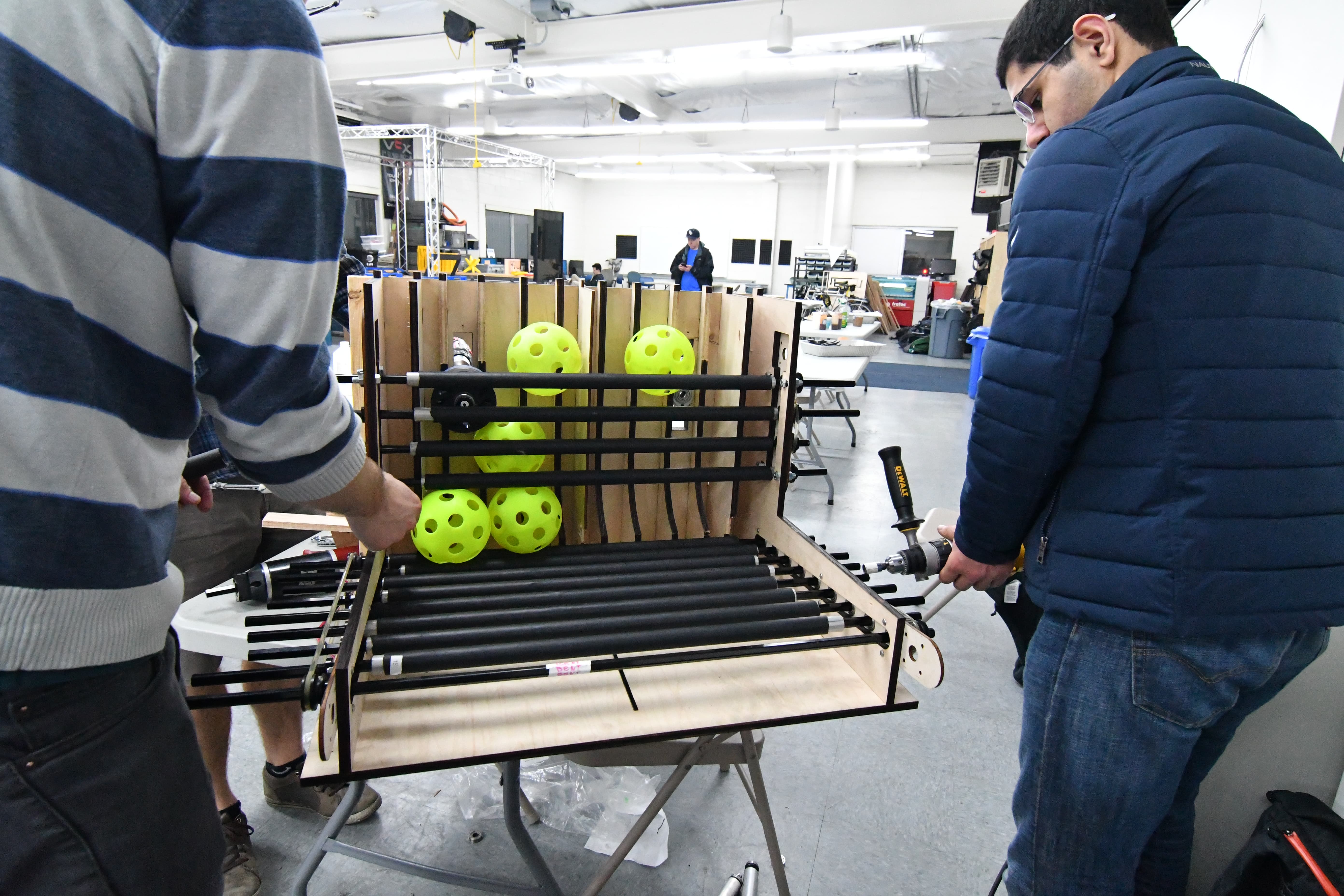
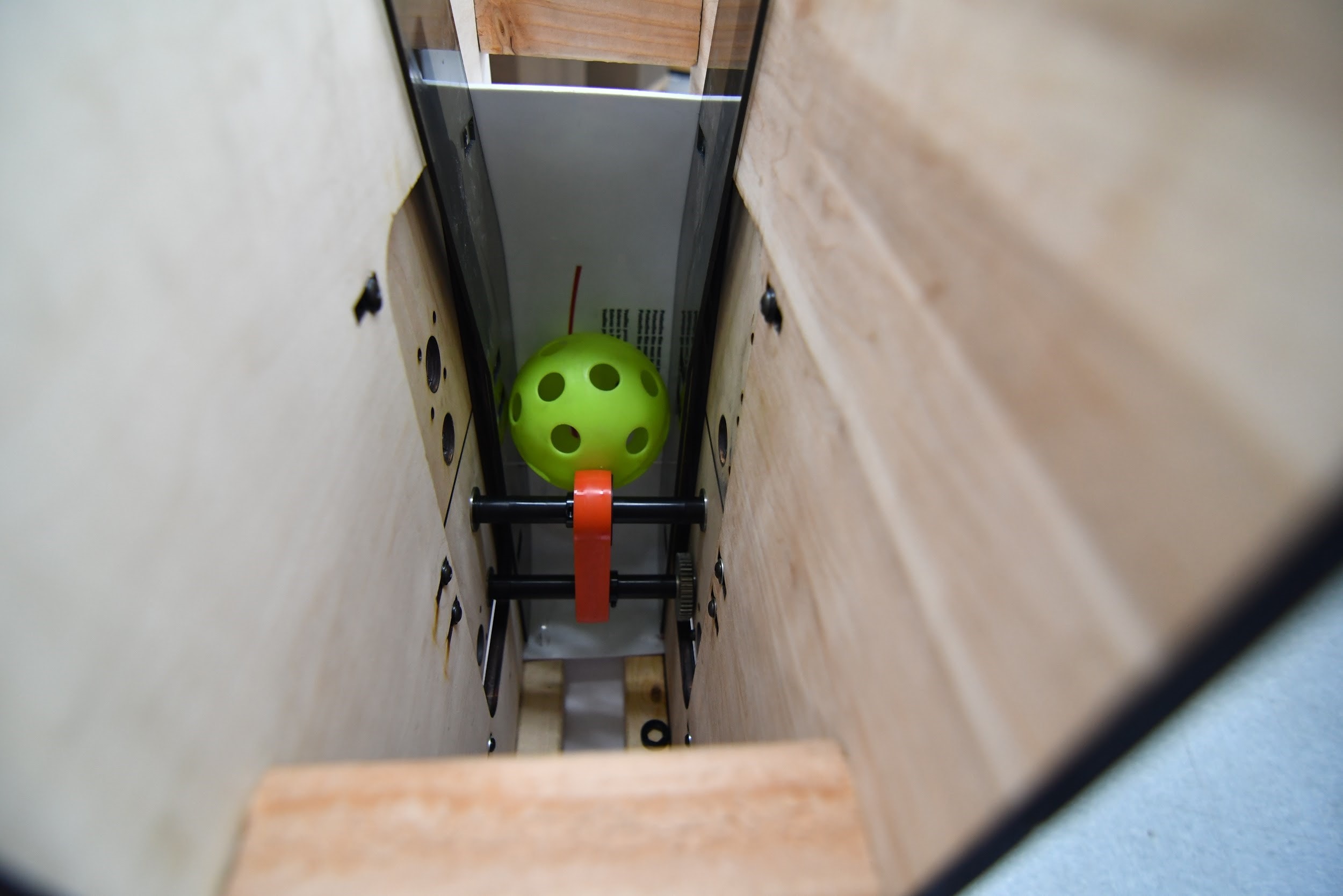
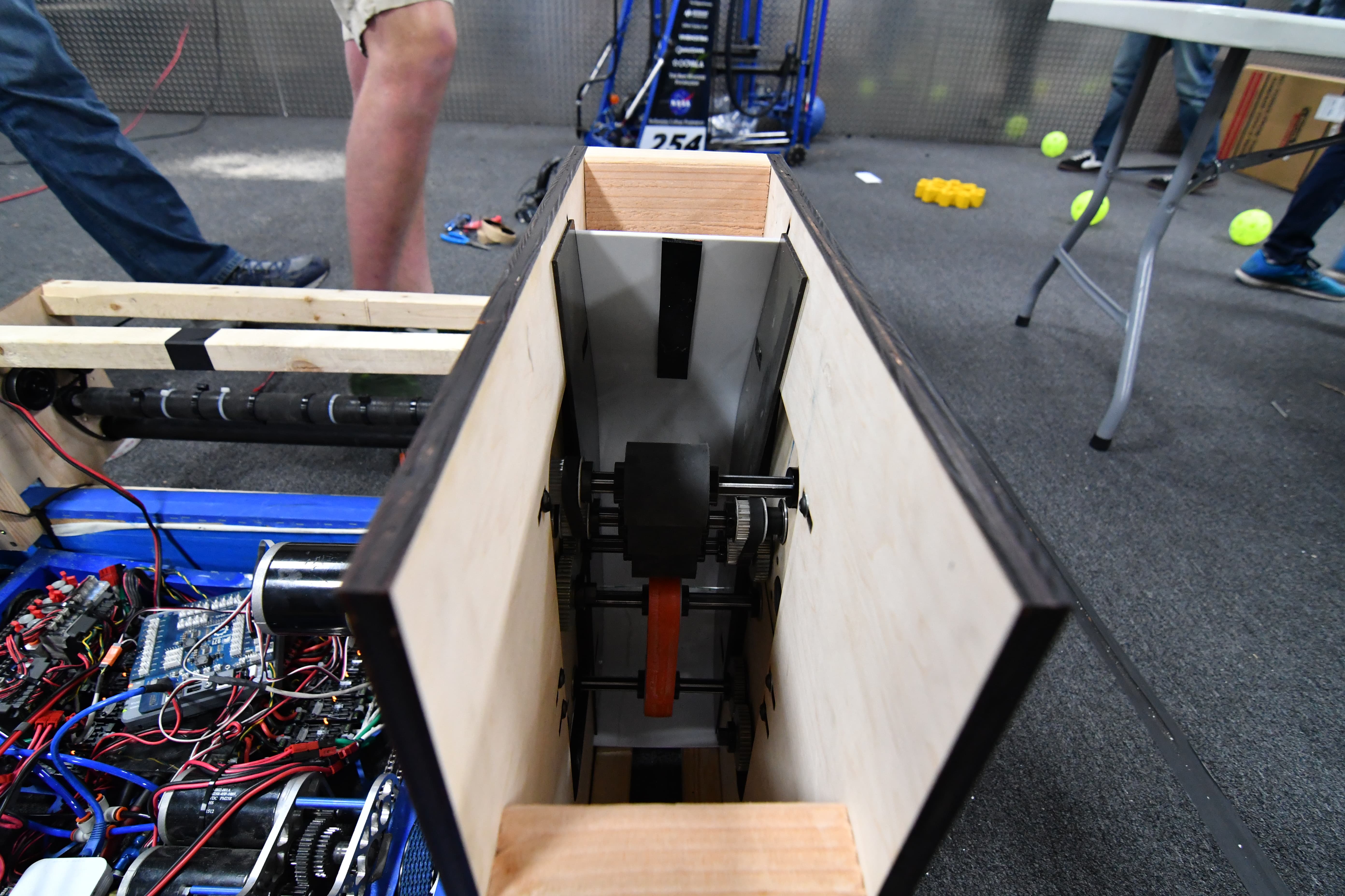
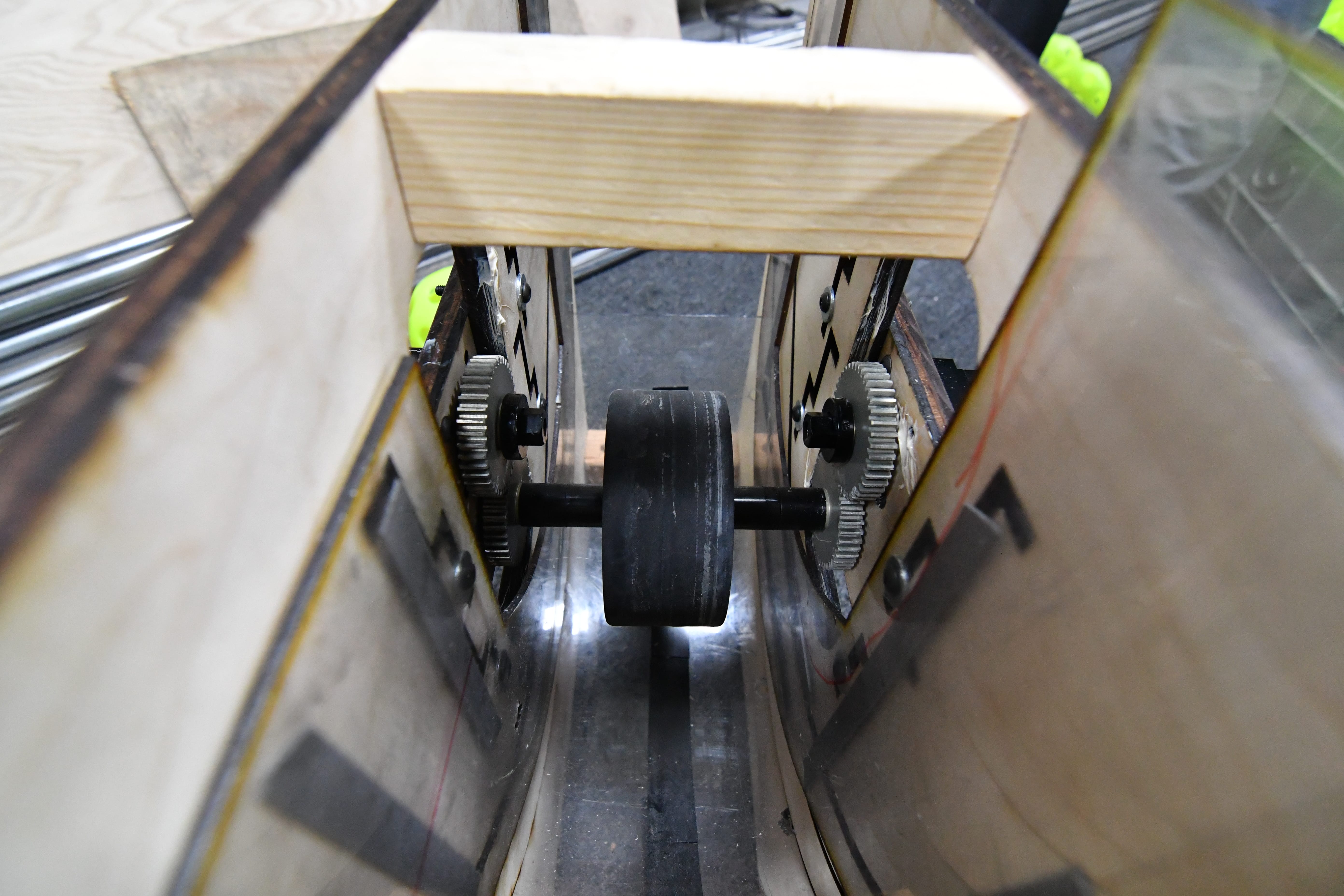
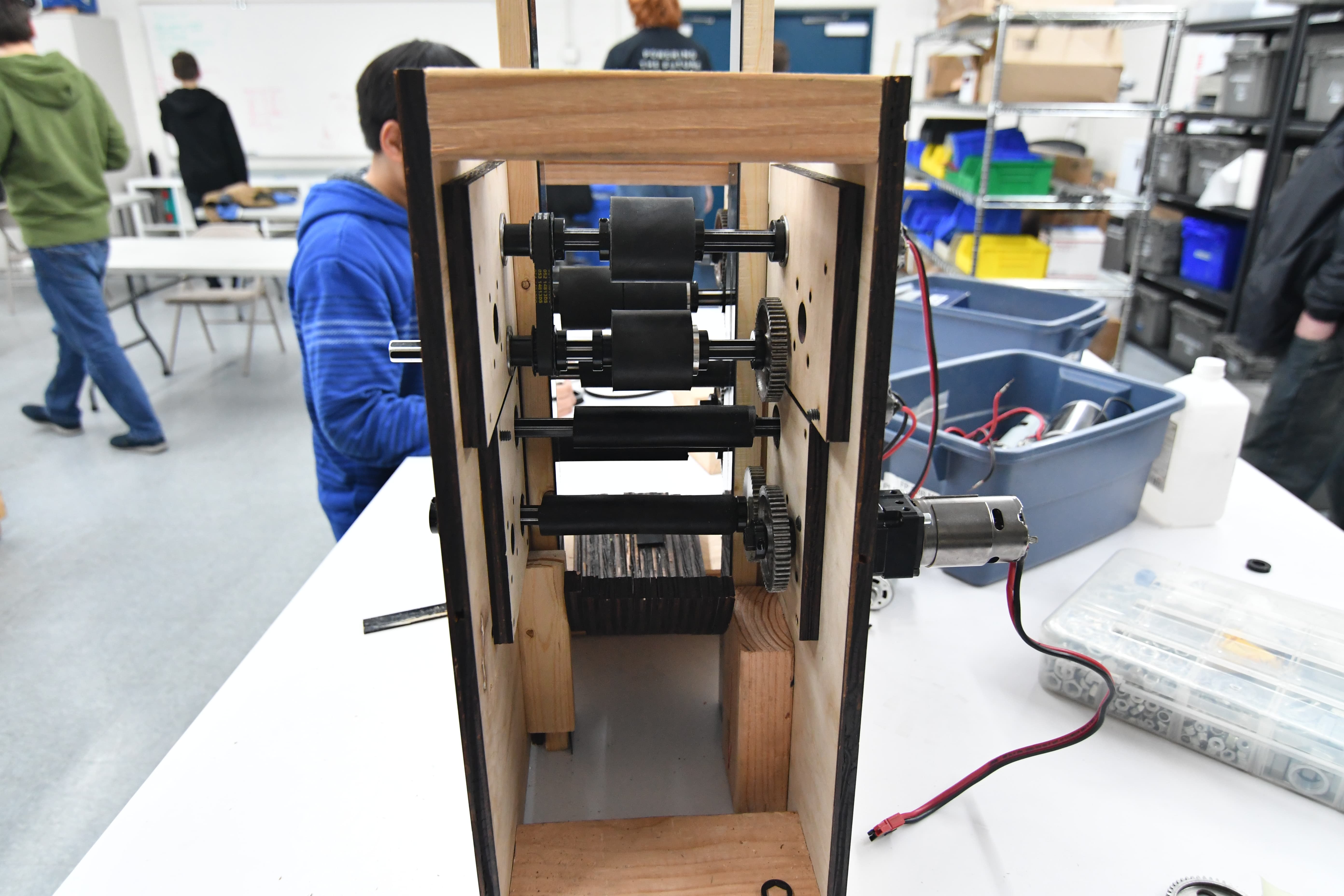
Hopper Floor
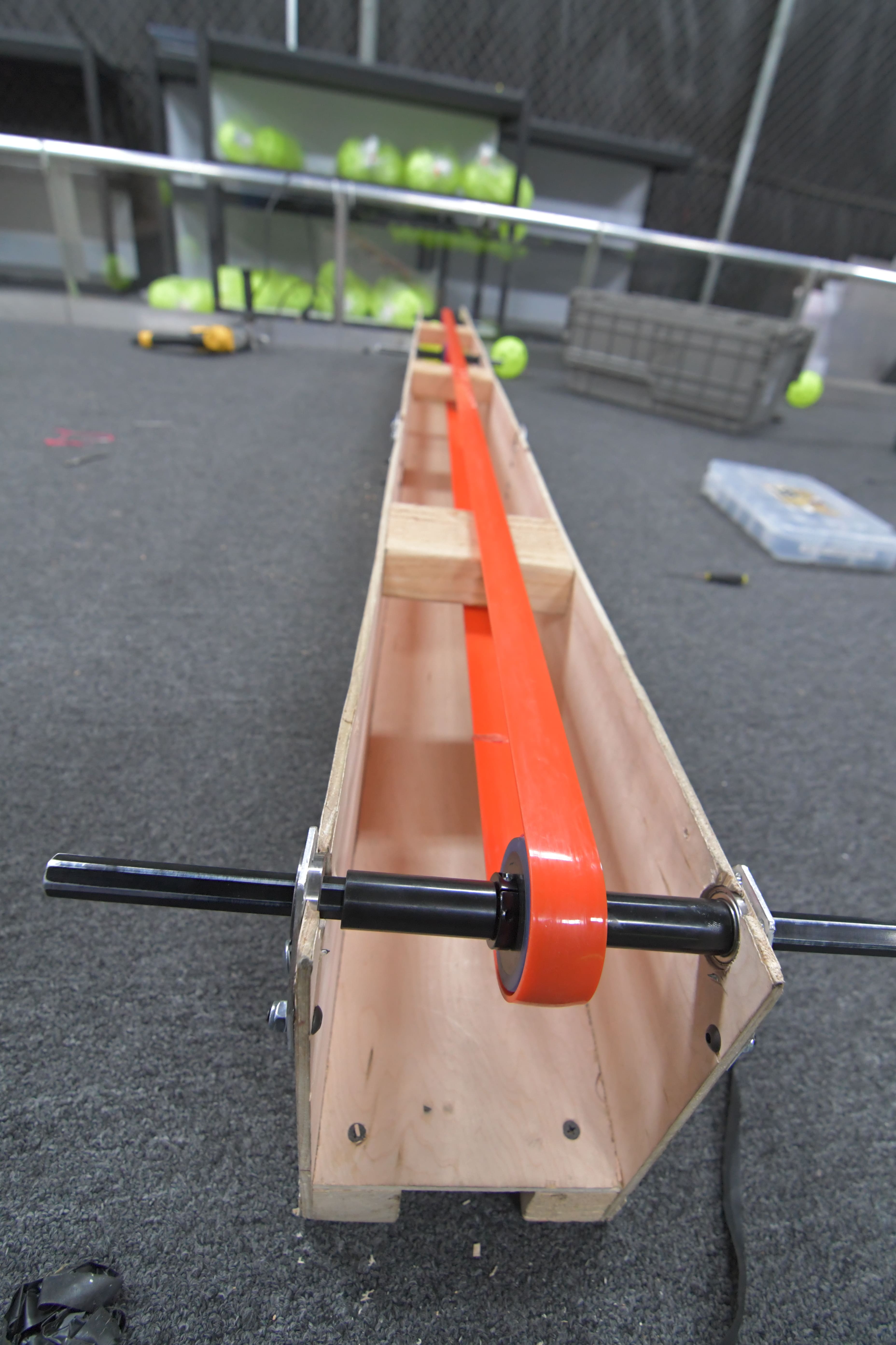
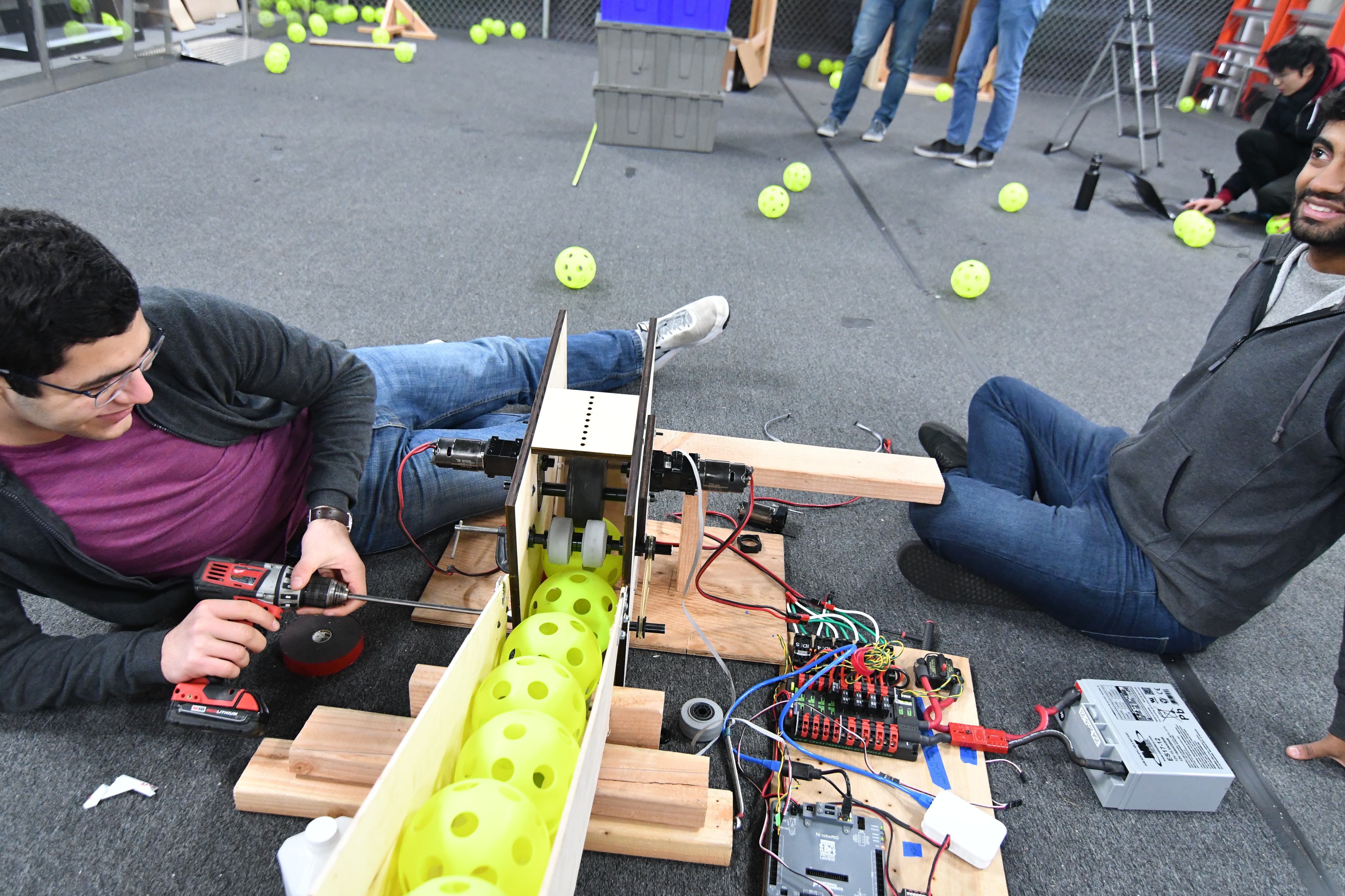
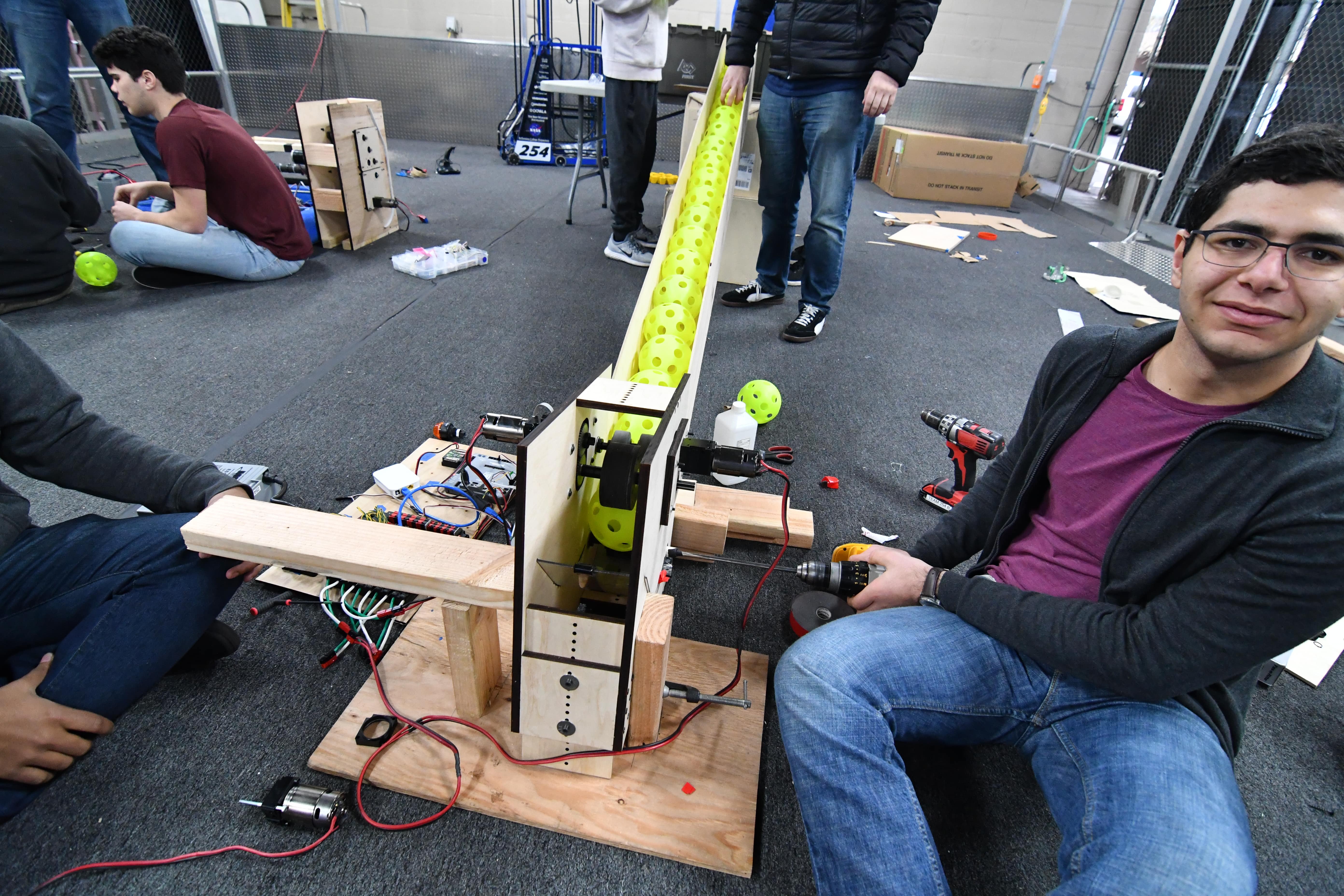
We took the top roller prototype that we have been working on, and added a center wall. The one from Monday was not long enough, so we extended it and stiffened it. We found this to help immensely. We also added zip ties across rollers to help the balls move across faster. We have reached a point where we are comfortable and confident with the floor.
CAD
We made progress on the hopper improvements in CAD and the redesigned Gear Grabber. We determined the geometry for the gear intake, designed the gearbox, and made the basic assembly that will be developed upon later.
Programming
Today, we worked on improving the web interface for the autonomous pathing tool. We improved the overall aesthetic of the app, and added several new features. These include the ability to see robot start and end rotation, and having the path colored based on the current speed of the robot.
FRC Day 31 Build Blog
Day 31: Continued Assembly and Programming
Hopper
On Monday, we worked on making the hopper more rigid as well as tackling other issues with it, including breach of size constraints and inability to actuate field hopper. We brainstormed and tested off of current practice-bot hopper with small team to determine solutions. We plan to change the front extension components to prevent them from expanding sideways by making it one piece. We will also lower the hopper to fold over the intake to give it greater strength and rigidity. As a result, the hopper will fold have slightly less volume for ball storage, but much greater strength.
Rope Climber
The rope design has been prototyped. The length and placement of velcro on the rope as well as the knot have been measured. The rope has not been tested or sewn on with velcro yet. Next build, we will attempt to prototype elastic and the placement of elastic on the rope as well as the amount.
Hopper Floor
We constructed a new top roller for the hopper floor. We also made few wedges at different angles to see which angle was best in directing each ball towards the shooter. Once we find the ideal wedge angle, we tested it. It worked well during the first test, but it was not consistent. Next time, we should keep experimenting in order to find the proper wedge angle.
Programming
We continued testing a ball counter for the shooter, but we were not able to count balls fast enough with the shooter on full power. For the counter, we’re using a Sharp distance sensor and creating a threshold that returns true when a ball is within range of the sensor. It is likely that our voltage threshold for the ball counter is too wide, causing some balls to not be detected.
FRC Day 29 & 30 Build Blog
Day 29 & 30: Getting Ready for Competition Season
Assembly
Hopper/Hopper Floor
Today, we worked on solving the funneling speed issue by placing a set of 4 rollers at the end of the hopper floor and above the wedges to provide a force pushing the ball forwards. This worked extremely well as our output increased to around 10 balls per second. More work needs to be done with different wheels and friction surfaces on the rollers and wedges to further increase our output.
Programming
We worked on pneumatically actuating the gear grabber by activating the solenoids individually. We are going to work on a state machine for Monday to make it more intuitive for drivers. We also deployed a sine scaling function to the driver inputs to significantly improve robot driving. We tuned the path following program by fixing some bugs and also investigated using the talon magic motion profile. We also developed the state machine for the gear grabber.
FRC Day 28 Build Blog
Day 28: Bag and Tag Day
Robot Progress
General Assembly
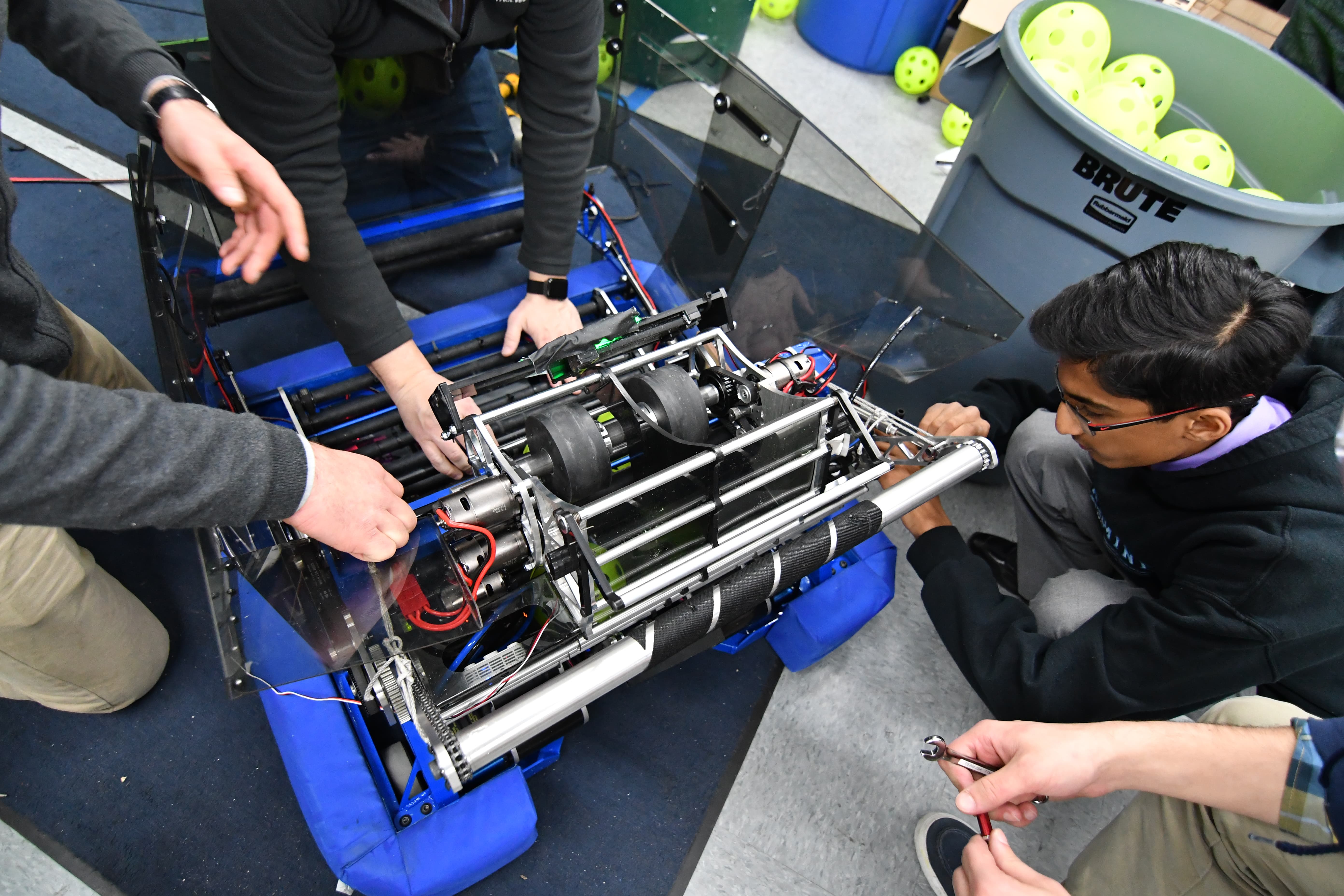
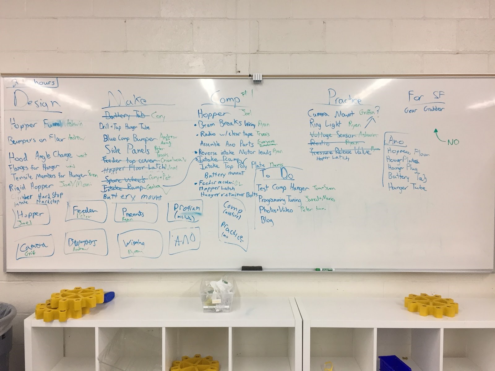
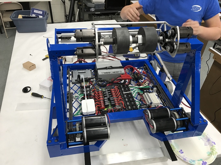
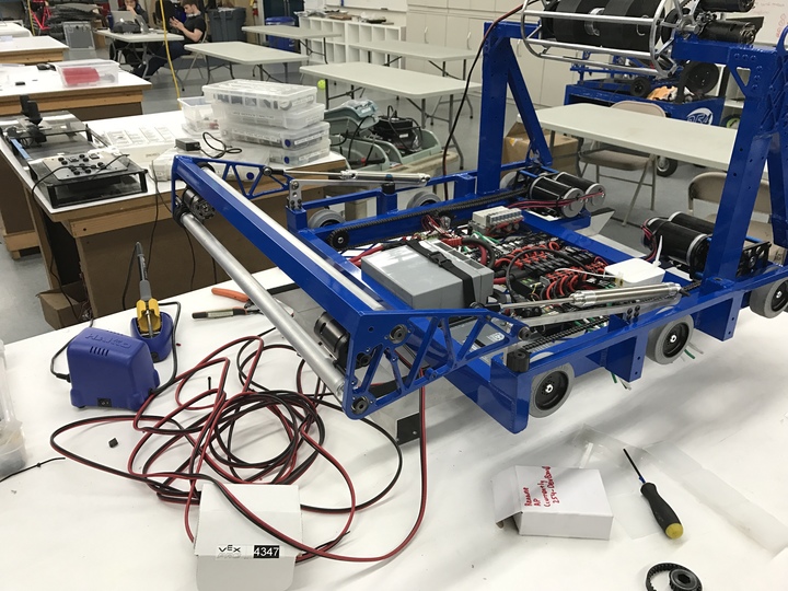
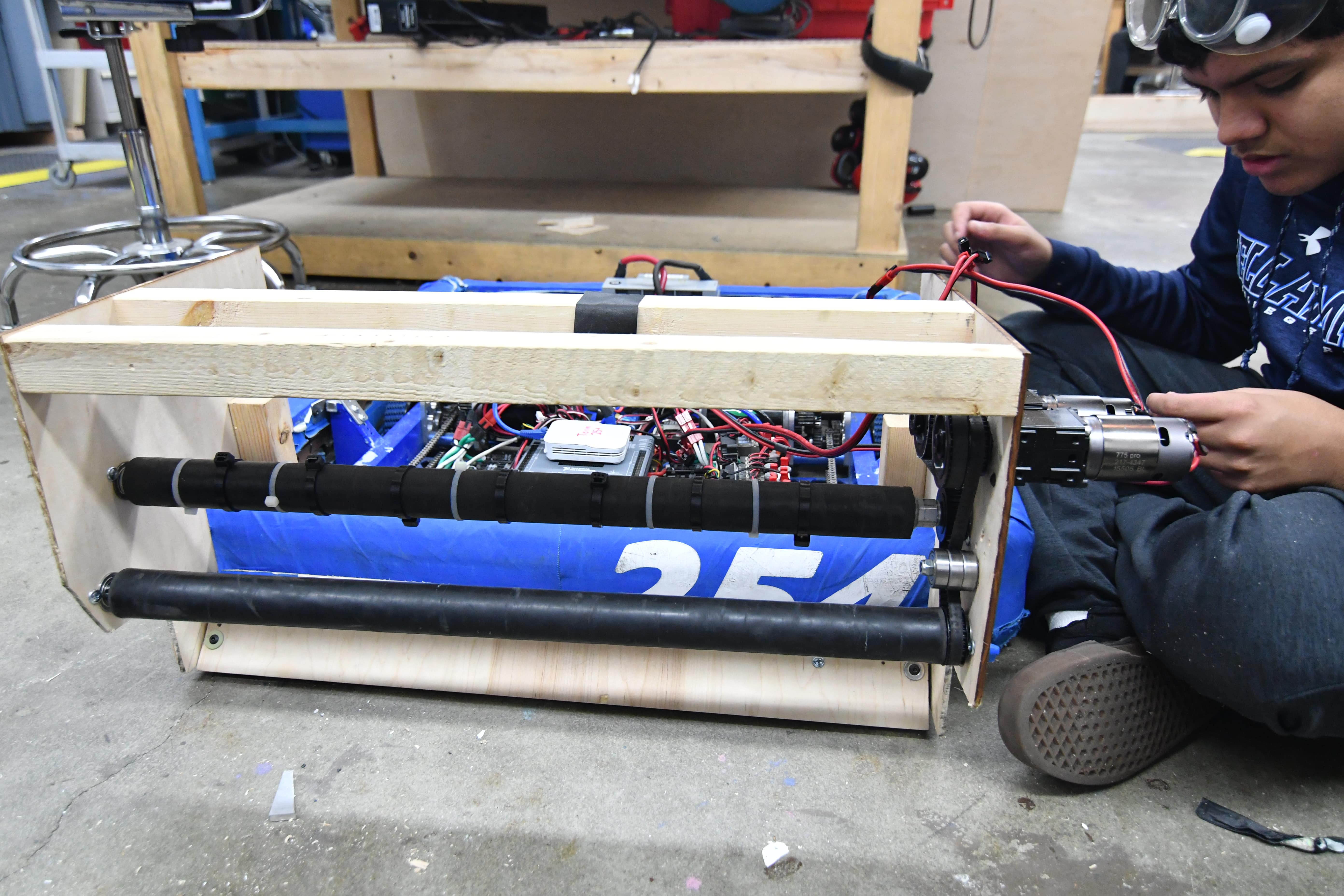
Today, we started by receiving news that after visiting 3 anodizing places, we could get parts for our hopper and hanger anodized for the competition robot. After calling, we knew that we would receive parts by 4, so we had to get everything ready for that time. The first thing we did was find every screw, every tool, every part, needed to assemble those subassemblies the moment they arrived. We then, finished the side panels and assembled the hopper. As soon as the parts arrived, we built up the entire robot and cleaned it, the best we could. We proceeded to take robot photos, and then diagnose the robot.
We also spent majority of the day working on a battery tab mount to keep the battery leads away from the hopper floor. The battery tab mounts to the PDP and fastens the Andersons together.
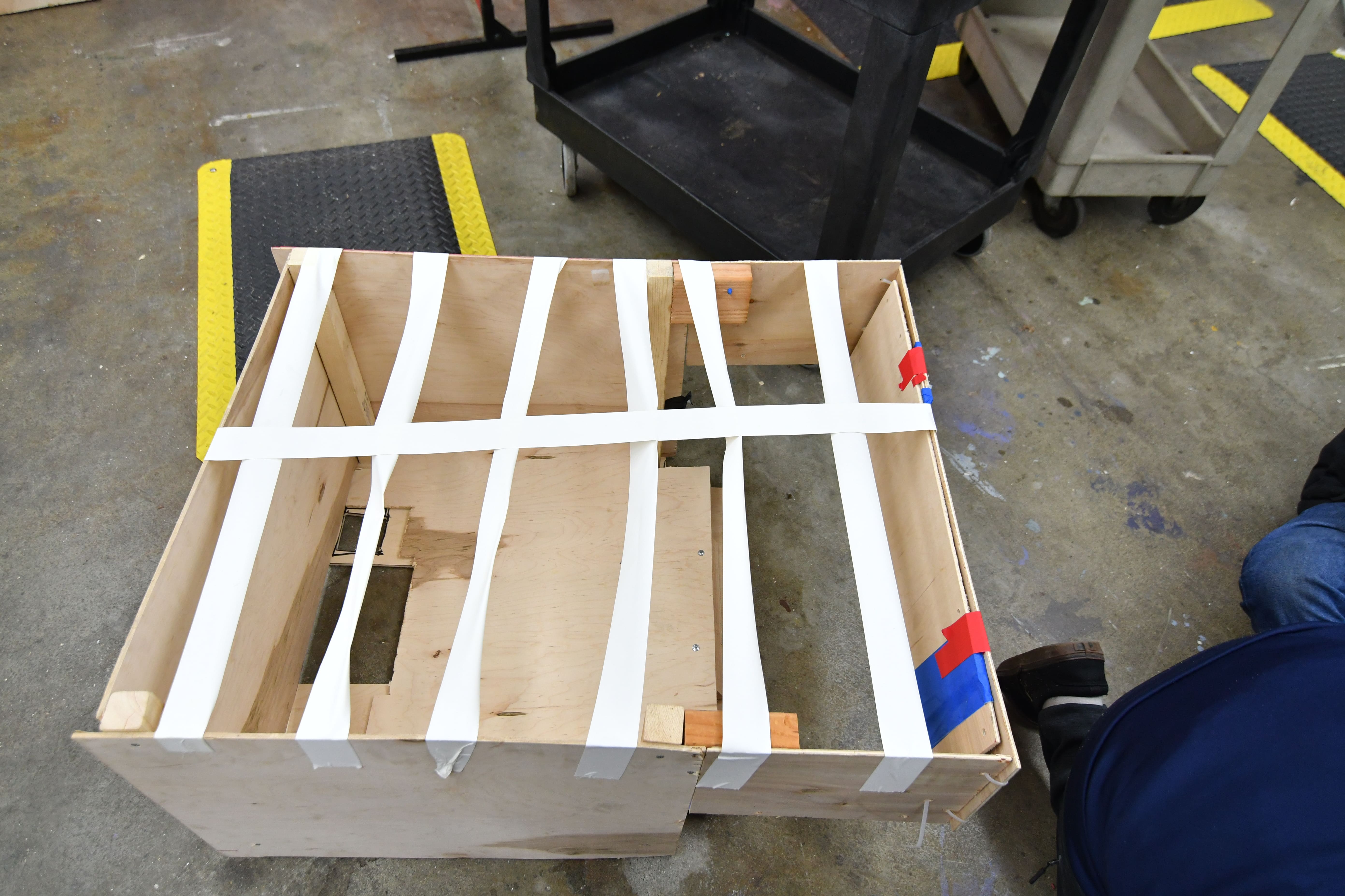
We found the shooter to have some issues that need to be dealt with, but physically fixing them must be pushed off until SFR. The robot was bagged around 10 minutes before 9pm.
Hopper Assembly
Yesterday, we worked on assembling and attaching the hopper container. While we waited for the anodized parts for the hopper floor and climber to come in, a group of students worked on assembling the main components of the hopper while carefully avoiding smudging the sponsor side panels before pictures. After prepping everything and waiting for other subsystems to be assembled and attached, we riveted and bolted on the hopper in under 10 minutes to allow media time to take pictures and then carry out any final checks before bag and tag.
Programming
Today, we worked on tuning our autonomous program some more. We discovered that the bug from yesterday was caused by two segments of the path not lining up, causing the pure pursuit controller to go out of control as it attempted to move the robot to the correct position. We managed to get a fully working autonomous mode that scored a gear, activated the hopper, then shot around 40 balls into the boiler. We noticed some inconsistencies with the gear scoring segment of the auto, most likely caused by wheel slippage. We didn't have enough time to fully resolve this issue, so we will continue to work on it this weekend.
FRC Day 26 & 27 Build Blog
Day 26 and 27: Continued Assembly and Programming
Assembly
Hopper
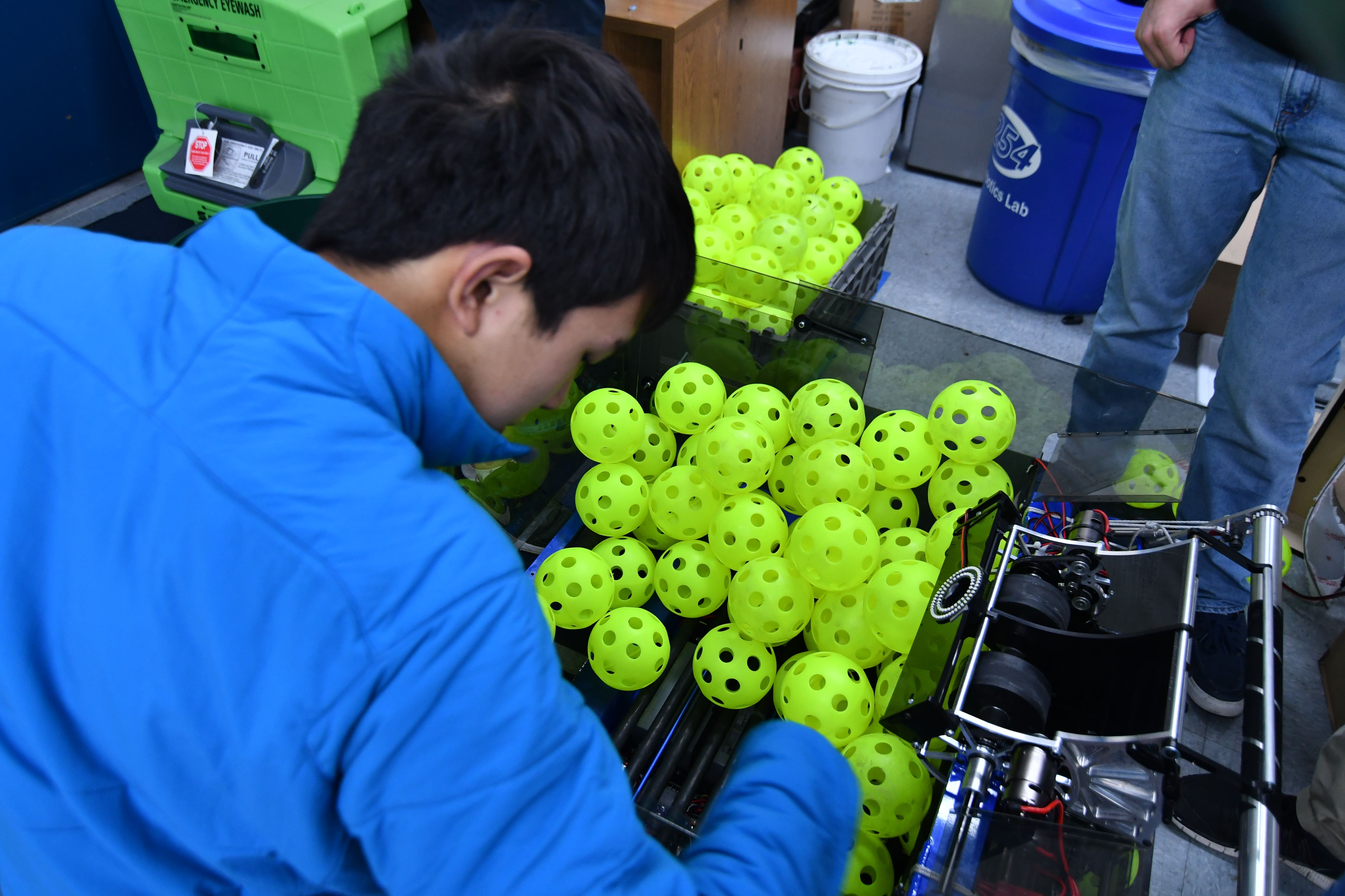
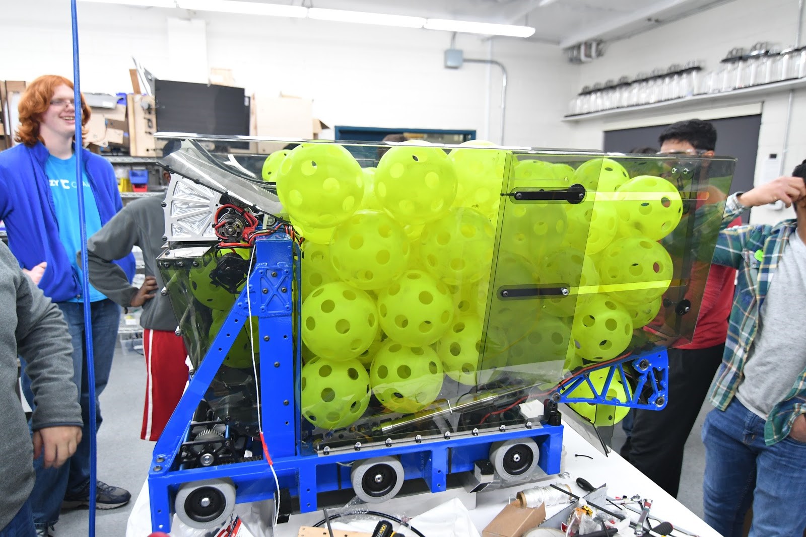
Today, we made sizable progress on the hopper. We made an initial prototype which we iterated upon to account for unforeseen difficulties. After getting it to deploy efficiently, we were able to store a max ball capacity of 140 balls. We are struggling with rigidity, however, as the 1/16 polycarbonate hopper flexes greatly when under stress from the balls and simultaneously driving. We will put aside fixing this problem for now as we have to finish putting together a robot for bag and tag.
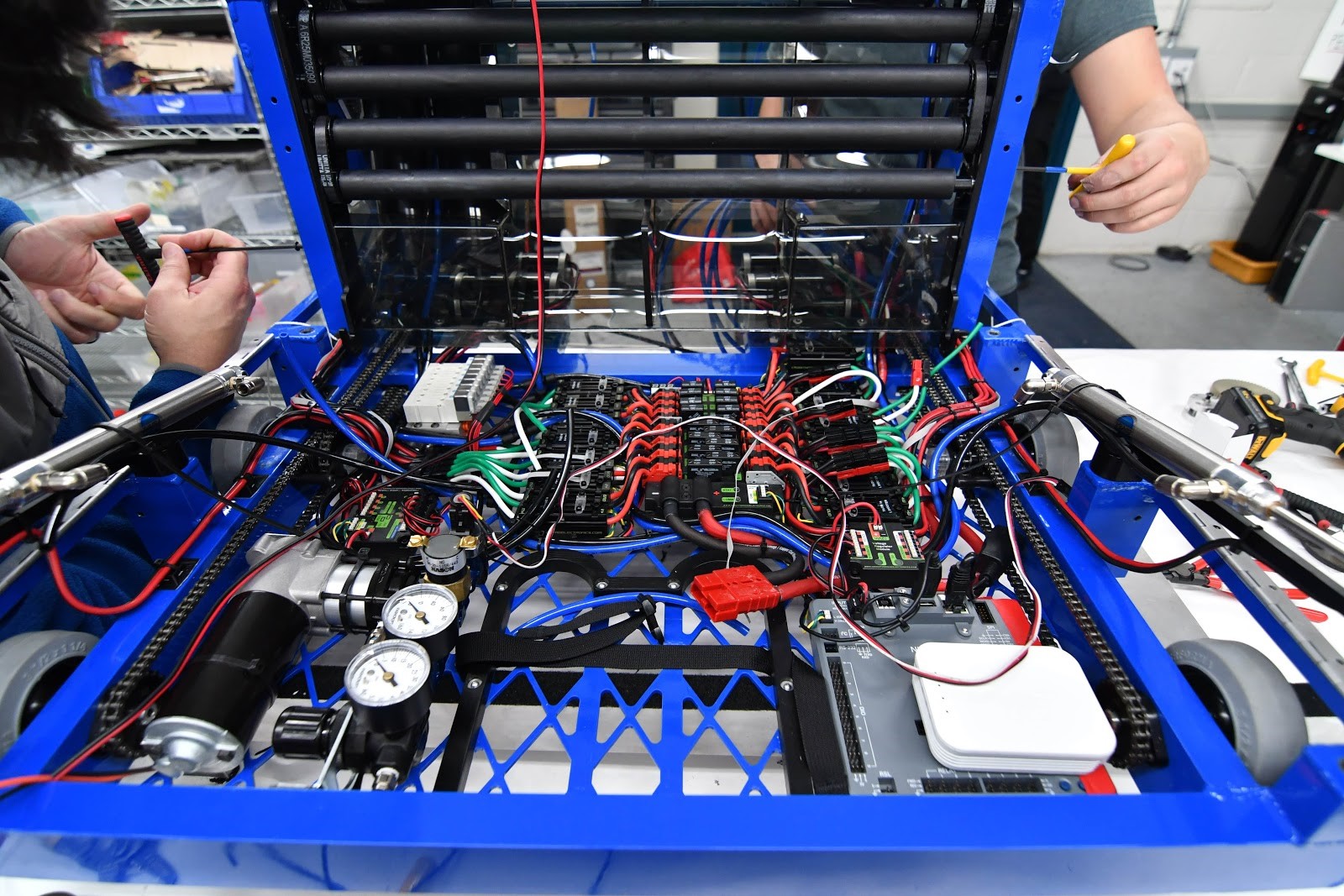
Wiring
We have almost completed wiring on the practice robot. We are waiting on a few competition subsystems to be assembled then we will be moving on to pneumatics. Last night, we had the robot shooting a few balls. Once we finish the hopper, we should be able to practice driving.
Gate Latch
On Sunday build, we worked on a hopper gate latch to lock down the assembly during the match. Changes still have to be made to make the latch feasible.
Hopper Floor
Today, we worked on assembling the hopper floor and finalizing it. We completely finished construction of the hopper floor. We worked on pneumatics and fixing the pneumatic tubing on the competition robot. We made progress on the side panels, which are coming along nicely. We also worked on general parts of the robot, but we still have a lot to do before tomorrow.
Programming
Today, we worked on creating an updated version of the Waypoint maker app. This new app outputs java files to load on the robot. We also created a parser on the robot which converts these waypoints into path segments for the Adaptive Pure Pursuit Controller.
Another project we worked on was implementing a turn in place autonomous action. We also made a couple auto paths to drop gears off and activate the hopper. We ran into some problems with motion profiling that we will fix tomorrow.
We rewrote the TCP server which sends data about the robot state to a web interface to be graphed. We used a library found on GitHub to do this. Next time, we will incorporate this into the rest of the Robot code and test it with the roboRIO.
FRC Day 24 & 25 Build Blog
Day 24 and 25: Continued Assembly and Programming
Assembly
General Assembly
We have almost completed wiring on the practice robot. We are waiting on a few competition subsystems to be assembled then we will be moving on to pneumatics. Last night, we had the robot shooting a few balls. Once we finish the hopper, we should be able to practice driving. The programming team finished vision tracking to auto-aim at the vision target on the goal.
Hopper Floor
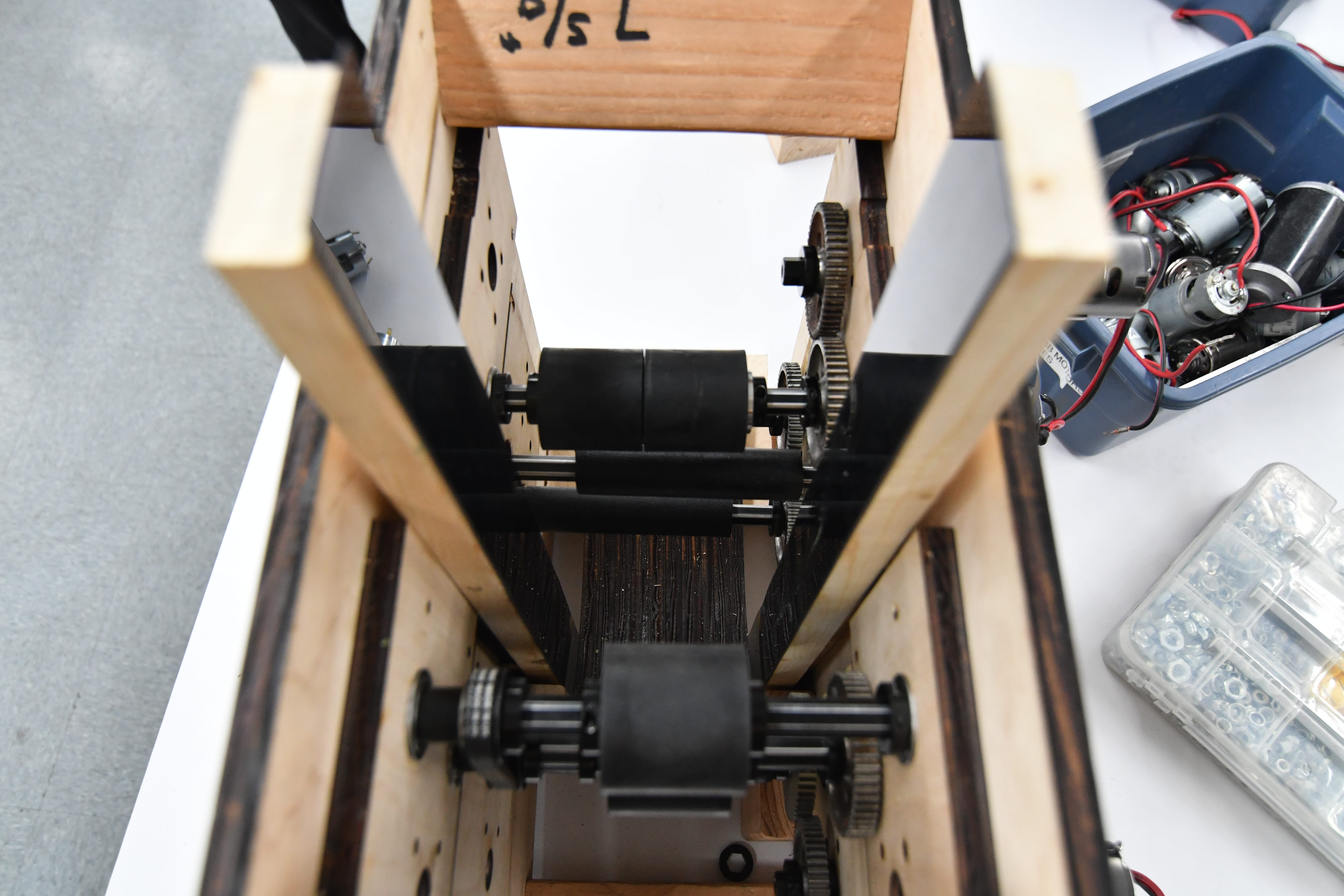
We assembled the hopper floor. The hopper floor originally had a .0010 nominal distance for the pulleys. After making the plates, we found that such a small distance caused too much tension, so we had to redesign it. We then, laser cut 5 different plates ranging from .0020 – .0060 of an inch.The .0060 of an inch measurement was the best way to go. Then, we put this measurement into the CAD and remachined those plates, which were put together. But, it was still too tight and required spacers in the standoffs. We put the spacers and it improved feeder consistency and reduced feeder tension. For the feeder, we had no way to service the 775’s due to very quick design restrictions, which would not be good at competition. So, we created holes on the side and top polycarb plates on the chute itself.
Hopper Feeder
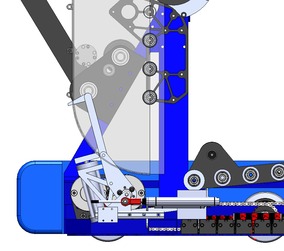
Today, we worked to lock down the design of the climber for the robot. We will be using a winch which it connected to a power take-off from the shooter to use the 4x 775 pro motors there to climb. The winch starts stowed against the hood and is deployed by pneumatic cylinders to the perimeter of the robot size box after the start of the match. Note that there will be hard stops (rope or cable) so that the force of hanging does not pass through the pneumatic cylinders.
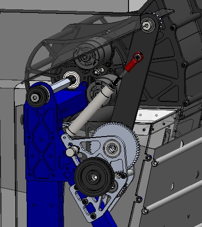
The winch is connected to the shooter shaft with a hex coupler and a pulley which rides on a one-way bearing on a shoulder bolt. When the shooter spins in forward, the bearing will clutch. When the shooter reverses direction, the bearing will lock and drive the winch. Note that the shoulder bolt is left-hand threaded so that the torque of climbing tightens the bolt.

The total gear ratio is 25.7:1 from the 775pro motors. This should give an expected current draw of around 80 amps when climbing. The 12:36 reduction is in the shooter gearbox. The 18:36 reduction is the belt between the shooter and the climber gearbox. The 14:60 reduction lives in the climber gearbox (with a 30T direction-reversing idler gear) and the 1:1 reduction is the chain from the gear box to the winch spool.

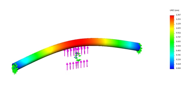
We plan to spool up a piece of velcro-coated webbing on a 1.25" diameter 1/8" wall thickness aluminum tube. FEA simulation shows that the expected bending on a 23" long tube of these dimensions should be around 1/16" in the middle (with purely elastic deformation).
Work still needs to be done on detailing the right side support plates, and the drum.
Bumper Construction
Today, we worked on building the bumpers for the robots. We made 4 bumper frames, secured pool noodles to the outside of all 4, and put sailcloth around 1. We will finish up the sailcloth tomorrow, and we plan to put on the team numbers soon as well.
Gear Mechanism
We assembled and began to test the existing gear mechanism with the "fingers", but it had a few flaws. One group worked on fixing the existing gear grabber, while another prototyped another design using compliant wheels and a polycarbonate wedge on the bottom. The initial prototype was promising, but needed some work in order to be consistent. We plan to continue working on both tomorrow.
Programming
Autonomous Path Follower
We began integration of the autonomous path follower into the main framework of our code and began debugging the path follower. We discovered some issues but were able to solve most of them.
PixyCam System
Today’s biggest accomplishment was finalizing all the state machines for the Superstructure. Because of this, we were able to automatically detected the boiler goal, align to the boiler, and shooter balls towards it. This is a major step forward since we were able to integrate across multiple subsystems.
FRC Day 23 Build Blog
Day 23: Continued Assembly Hopper Progress
Robot Progress
Almost all our parts are back from anodizing and we are trying to rapidly assemble as much of the robot as possible. The team working on putting surgical tubing over the rollers is almost finished and just needs to trim the excess off of each edge. The intake team finished assembling their first subsystem and is ready to mount it to the robot and assemble the rest. They had some trouble locating the appropriate timing belts, but now are ready to assemble. The shooter team also collected all their hardware. They just need to laser cut the rest of the polycarb and delrin plates, assemble the other shooters, and mount on the robot. Superstructure wiring was set back when we had to unfish the wires and drill additional holes in the weldment, and we are not back on track and ready to terminate the shooter wires. Late in the evening, a team of students and mentors stayed late to double check our inventory to ensure that we have ordered everything that we need to complete the robot by Tuesday. We are hoping to finish assembling intakes, shooters, and feeders today and at least one conveyor assembly as well. Wiring should be able to finish the practice and comp robot shooters and begin wiring the other subsystems.
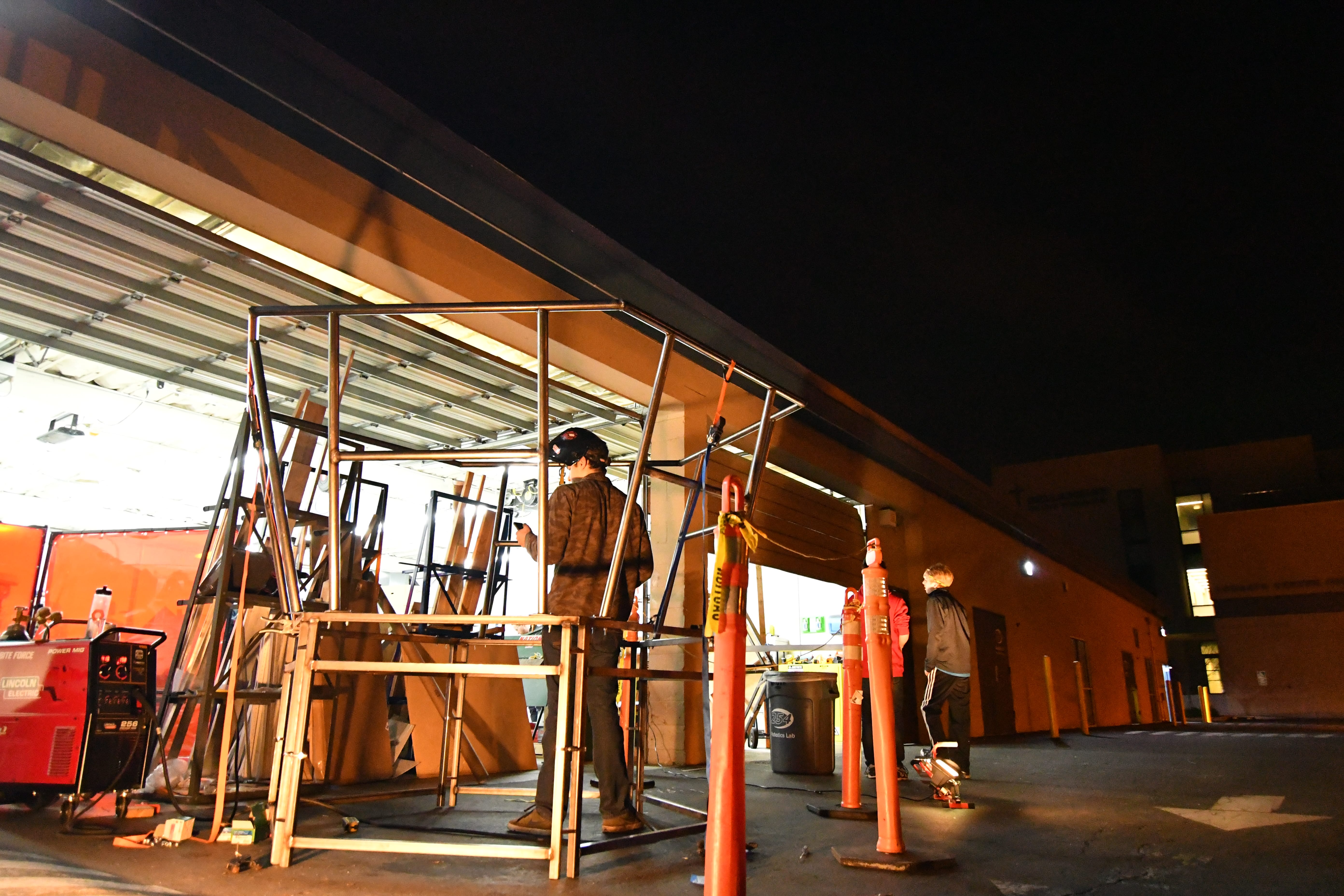
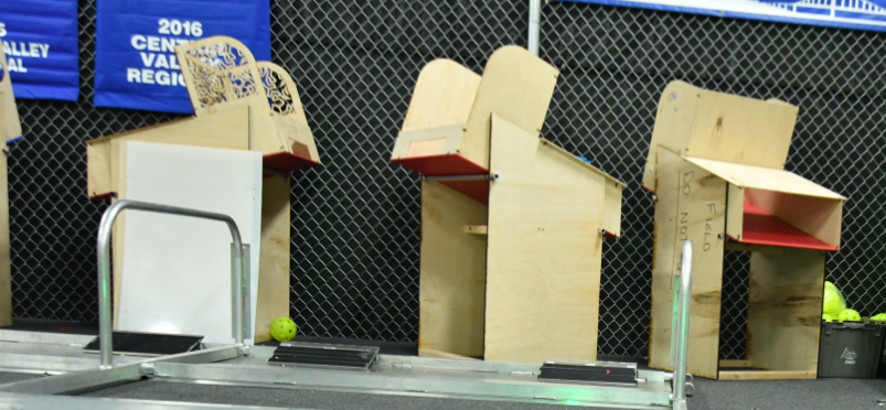
Field Construction
Today we have finished all the feeders for the field by attaching the tops to the base. We have all the polycarb cut for the hoppers, but need people to cut the pipe that slides in and zip tie them on. The prototyping for the driver station to boiler mount is almost finished. The final idea has been decided and is going through final stages of being designed. The 2×2 wood for the boilers net have been cut, and all that is left is to place them on and attach the netting.
Programming
We decided to scrap the PixyCam system and use two separate camera systems, the Android phone, and a webcam connected to the RoboRIO. The Android phone system is the same system that we used last year but trained for this year’s boiler targets. We worked on getting the phone mount ready to mount on the robot. The webcam will be used for the gear placement; it connects to the RoboRIO via USB and serves live video to SmartDashboard via MJPEG. We were able to view a live stream of video on SmartDashboard, and we began work on identifying the boiler targets with the webcam’s stream on the RoboRIO.
We also worked some more on the Autonomous Pathing system. First, we got the pathing system working with the new RobotState class, replacing the old Odometer class to keep track of robot position and heading. We also added linear interpolation to the lookahead point of the last segment of the path. This was in order to fix a problem where the robot would jerk sharply at the end of the path, causing its heading to end up out of place. Finally, we worked on tuning the wheel radius so the RobotState class would give a more accurate position. After making these improvements to the pathing system, we worked on tuning PID for the drivebase using the built-in talon PID control. Tuning Kf went smoothly, but we ran into some problems with tuning Kp. Even extremely small Kp values would cause the robot to turn wildly, and we weren't able to find out exactly what was causing this problem today.
FRC Day 22 Build Blog
Day 22: Finishing Up The Field
Robot Progress
Today was a productive manufacturing and assembly day even though we didn't have our anodized parts back. We took off the superstructure today to make holes to run wiring from the shooter and feeder motors and encoders from the top of the superstructure to the drivebase. We began fishing wires, but were not able to finish because we have to add more holes to the superstructure to mount the feeder roller plates. Tomorrow we should have several parts back from anodizing and we can begin to assemble several subsystems including the intake, superstructure, shooter, and feeder. Manufacturing will also continue on the hopper polycarb pieces.
Field Construction
Today we finished up all 6 of the feeder stations for the field. We also changed all the plastic from the previously used HDPE to the new official colored plastic, which allows gears and balls to slide down it much more easily. We plan to continue with field work, with the next tasks being to finish the more complex airships and assemble the field side walls/driver stations.
Programming
We made leaps and bounds towards cleaning up our Github codebase and making work far easier Previously, our codebase had sprawled across multiple branches, each with their own versions of essential robot code, which made collaboration difficult. We merged the latest autonomous and camera code into the master branch. In the future, we will ensure that all code remains within three commits of the Master branch, and we will pull far more frequently.
We also began integrating the code for the Nexus phone camera system, as well as the robot state machine, into our codebase. The Nexus vision system was used with great success last year but is far more complicated than our PixyCam system. We will test the PixyCam again, using the central point on the top segment instead of the centroid (a far more consistent, reliable means of estimating the distance), and the accuracy/reliability will determine whether we use the PixyCam or the Nexus phone.
The drivebase PID control was tuned for our unweighted robot drivebase to compensate for mechanical differences. Previously, we set a constant voltage to the motor to control the robot’s speed, called open-loop control. This does not take into account different mechanical differences, like gearbox lubrication or bits of carpet stuck in gearboxes (a problem we saw). Now, instead of swerving, the drivebase drives in a straight line!
Finally, we began work on integrating an infrared laser distance sensor into our robot code. The sensor turns on a high-power infrared laser beam and measures the time taken for the beam to reflect back to a detector, then uses that information to calculate the distance between the sensor and the object. This “time of flight” sensor has great accuracy, and we envision using it in conjunction with our camera system to accurately measure distances and aim appropriately.
FRC Day 20 & 21 Build Blog
Day 20 & 21: Field and Robot Construction
Robot
We are focusing heavily on manufacturing to make sure all the parts for the robot are ready; we sent several parts to anodize this morning. We also have a shooter and intake assembled and hope to finish the feeder chute assembled in the next two days.
Field
Today we worked on further field development. We have gotten to a point in which we are waiting for material resources to proceed. We accounted for field development mistakes, and finished the boilers. In addition, the top pieces of the airships were mismeasured, and must be recut and rewelded. We also focused on the feeder stations for the gears and balls. We laser cut the majority of the parts and manually cut the rest of them on the chop saw/bandsaw, and then assembled 6 feeder stations to make a full field. 2 are completely done, and the other 4 are all missing one piece before they are also done. We hope to finish the field by Monday night.
CAD
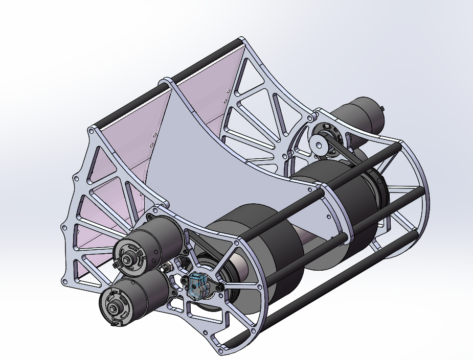
We have completed the CADs for the Bumper, Intake, Shooter, Superstructure, and Drive base – all of which have begun manufacturing/assembly or will be soon. The Intake is a two-roller assembly powered by two 775 Pros in a 3-1 gear ratio with a polycarbonate ramp to assist the ball path as it enters the robot. The Shooter is two 4” Fairlane Single Wheel Backspin shooters side-by-side powered by 4 775 pros. This will also power the Velcro-winch hanging system at the end of the match.
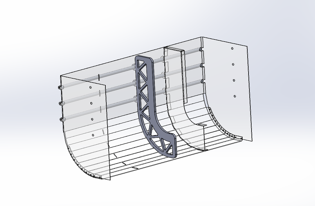
We made lots of progress on the Hopper Container and Conveyor and will hopefully be able to begin manufacturing soon. For the hopper container, the width-expansion constraint geometry needs to be finalized and the bend radius on the actual break needs to be accounted for in the bend radii on our “sheet metal” plastic parts. The conveyor at this point in time is complete, we are currently finishing up the detailing of screws and etc. This is waiting mentor approval before manufacturing. The Feeder and Chute are done for the most part, they only need to be confirmed against the final geometry of the conveyor floor which was finished today. Progress was made on the climber subsystem today, as well.
We worked on a flange for the Velcro drum/roller to displace the touch sensor on the davit with a 3-part rotating flange that stows within the frame perimeter and deploys like a fan with surgical tubing to a circular flange encompassing the roller and providing enough distance between the OD of the flange and the OD of the roller (with Velcro bundled) to displace the touchpad approximately .5” – 1.5”. Moving forward, we want to begin manufacturing on as many things as possible, while fine tuning and checking for interference in CAD. A semi-detailed list of next steps in linked above.
FRC Day 19 Build Blog
Day 19: Prototyping, Drivebase, and Programming
Prototyping
Shooter
The shooter design is almost done. We are moving forward with 20 degree trajectory and tangent hood section out to 45 degree, to match the prototype. It should be ready to make this weekend.
The chute design is coming along. We will need to make it angled to fit gear grabber.
Gear Intake
The gear grabber concept is complete and detailed design is moving along well. We should be able to make it by early next week. We need the chute mods to be able to hold the gear and fit it in the sizing box.
Drivebase
We worked on getting the superstructure ready for powder coating after welding. Then, we put holes in the frame to attach the superstructure to. We also then made some parts for intake well we CNC the other parts for the intake to get it ready for welding today. We also organized the metal in the shipping container.
Programming
On Tuesday, we tested our autonomous path code, which uses a web interface to plot an autonomous robot path. It worked; the robot moved along the plotted path with ~2 inches of its target! There were a few kinks that we are still resolving, though. The robot uses a NavX IMU (inertial measurement unit) to determine the robot’s heading, and the NavX board was throwing errors because there were multiple instances of the same board. This was resolved, but we still have to clean up the code to avoid these issues in the future. At the end of the path, the robot unexpectedly darted backwards; we have to fix that.. Finally, we tuned the drivebase PID constants for low gear but need to do the same for high gear, which the robot will likely operate in.
Today, we also revised the PixyCam software in order to make it more threadsafe. Rather than our current model, where we make calls to a PixyCam object, we changed the code to use a Listener interface- the PIxyCam object publishes an “event” whenever targets (aka “blocks”) are detected, on a different thread, and a listener on the main thread will handle each block when necessary. This makes the code more threadsafe- if the SPI driver crashes, it will not bring down the entire robot.
We also corrected the PixyCam distance estimation formulas to be much more accurate. Before, we were using the block height and width to calculate distance. However, the block height and width are very susceptible to noise and change minimally with distance. We switched to using the centroid of the target, which is far more evident to the PixyCam and therefore more accurate. We were able to calculate the distance to the boiler, plus-minus 10 inches, likely because of our setup and camera calibration.
For the drive code, we added in the ability to shift between low and high gear (using the pneumatics). We use the low gear mode on the robot when we need to move slower, but with more torque/power (e.g. when we’re aiming to shoot), and we use the high gear when we are barreling full speed down the field. Shifting is accomplished with pneumatics and dog collars. This is not quite a six-speed manual transmission, but two speeds is sufficient for our needs.
FRC Day 18 Build Blog
Day 18: Hopper Progress
Prototyping
Hopper / Feeder
Today we continued work on the hopper/feeder prototype. We went through a few more iterations revolving around the central design of a powered floor of rollers, but nothing seemed to stand out as notably better than what we started with. We tried putting Teflon tape on certain parts of the rollers to speed up feeding and we tried moving the ridge that creates two channels of balls higher up. We also experimented with passive back-feeder funneling methods, but realized that having a passive funnel in the back would be difficult to design with our high throughput goals in mind. None of these led to a significant improvement in the feeding rate. Going forward, we are most likely going to manufacture and use the powered floor with rollers, although it does leave some performance to be desired. Next build, we need to test the conveyor system and a center peak in the hopper itself.
Construction
Today, we made progress on assembling the bumper mounts and robot stand.
FRC Day 17 Build Blog
Day 17: Prototyping, Drivebase, CAD
Prototyping
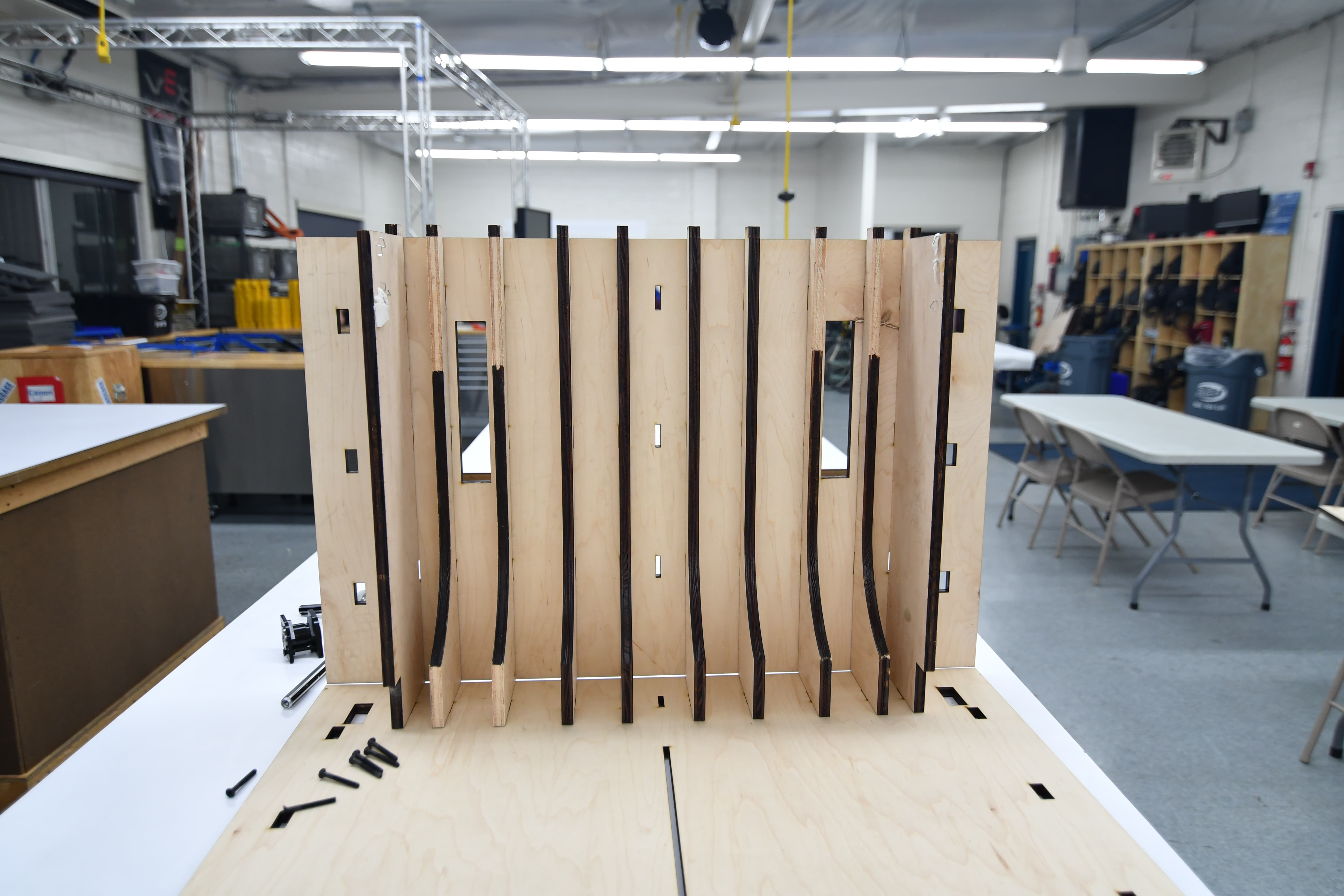
Zipper Hopper
Today was essentially our drop dead date for finalizing 90% of the hopper in CAD. We took our roller design and decided to ship it, with a center to center distance of less than 50mm, as the 55mm on the prototype was too much. While the CAD team was designing, we iterated on funneling methods and found that we could probably use a passive funneling method on the base of the hopper. This passive method worked surprisingly well. We also found that the zip-ties we added onto the rollers did their jobs too well. They acted as small 'fingers' and flung balls. While this is the intended effect, we did not want this at the end of the hopper, and removed the zip ties on half of the prototype. This solution decreased entropy and increased throughput. The design that we have now isn’t the best it could be, but has been designed with adaptability in mind for the future. After deciding on rollers, we continued to iterate on the design with wrapping cloth over the rollers rather than simply belt. We found that this solution has promise and decreases popcorning of the balls. We will continue to iterate on this method next build. We also theorized that if we create a large enough crown on parts of rollers, we might be able to have a significantly faster feeding method with little no change, that could also increase throughput. We will work on this next build as well.
Intake
Today, we finalized the intake prototype after many iterations, and it was CADed into the current robot design. It performs very effectively, being relatively light and simple, but still meeting the goal of picking up every ball in front of the robot at top speed. One improvement that led to the final design today was switching the 1/4" wall surgical tubing on the rollers for 1/8" wall surgical tubing (and adjusting the geometry accordingly), which performs the same but saves a whole pound of weight. Another key change was the ramp, which was changed to 3.5" long rather than the previous 5", and was made intentionally flexible to allow faster intaking and less bogging down as large groups of balls come in simultaneously. The plan for the future is to finalize the intake CAD and to manufacture/assemble it.
Testing:
Gear Intake
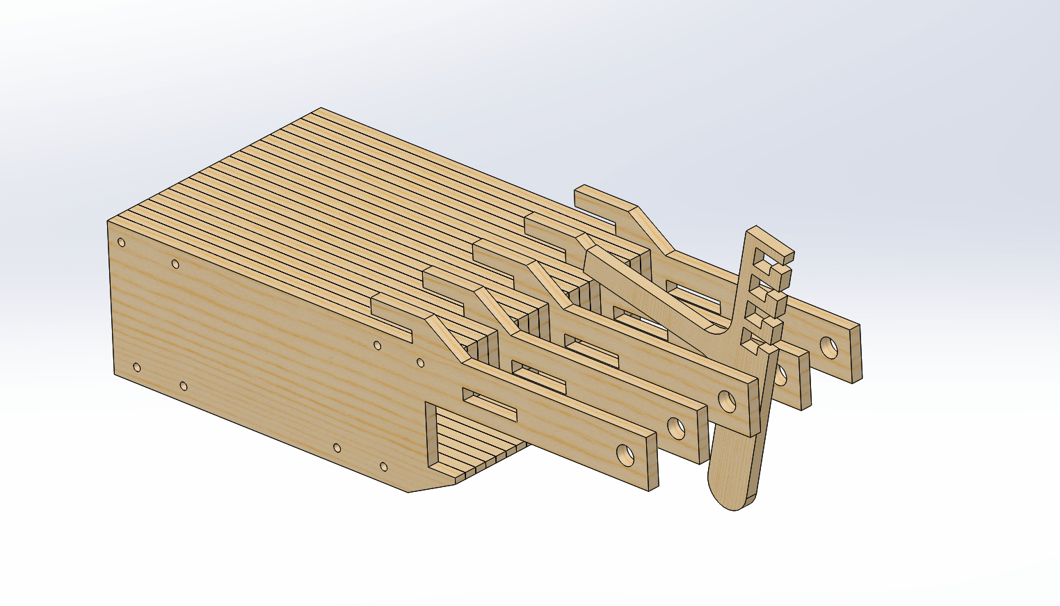
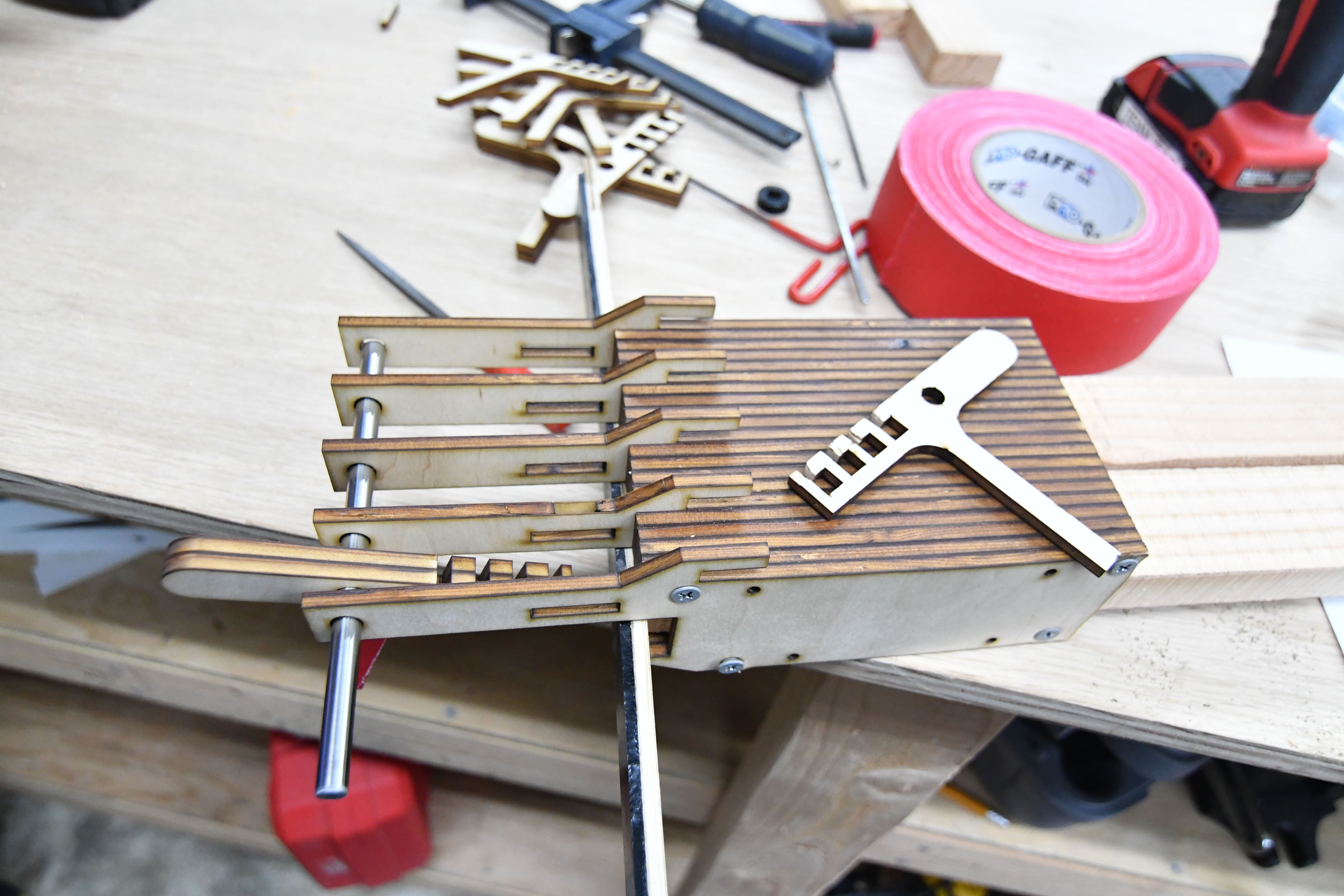
Today, we worked a lot on the gear intake. Although previous prototypes had been very successful and gave us a really good starting point, one factor we hadn’t looked into very deeply was the sizing constraint that we would have to work around. In order to figure out the geometry and work out generally how the system would work, we evaluated a bunch of different variables, including changing the bore size for the compression system, as well as modifying the rotating system so that it could package and deploy within the sizing box of the robot. Once we figure out these details, we then began designing the parts in Solidworks. The next step will be to finish the design of the the actual system itself and then look into possible mounting solutions for the rotating system that will connect the claw to the robot itself.
Drivebase
Today, we assembled the drivetrain of the robot including the gearboxes and chain. We finished the drivebase wiring for one robot and had it driving on the field for the first time! We also built and mounted a lasercut delrin battery box. We are waiting on a few last CAD details and a few parts to finish the drivebases of all three robots.
CAD
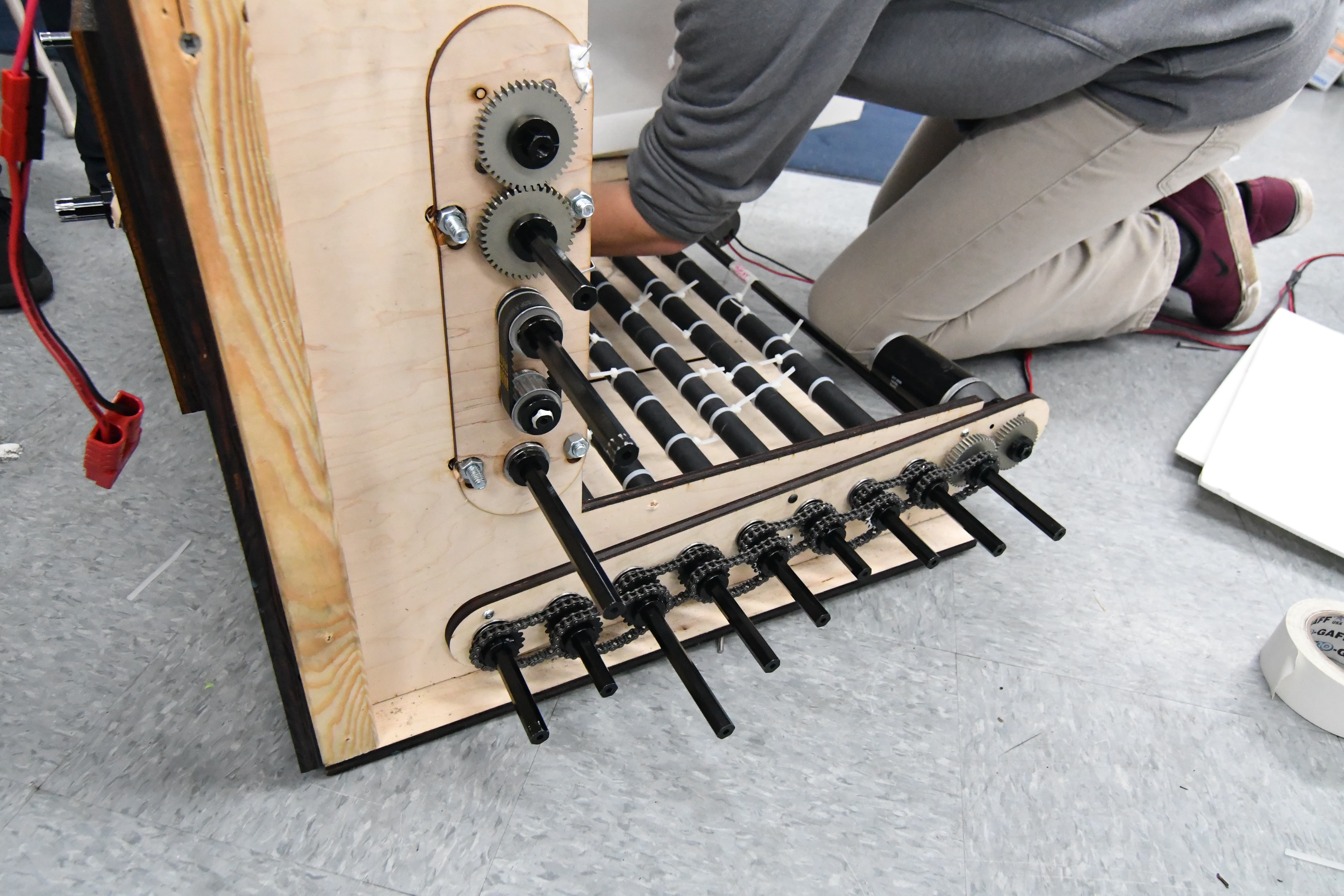
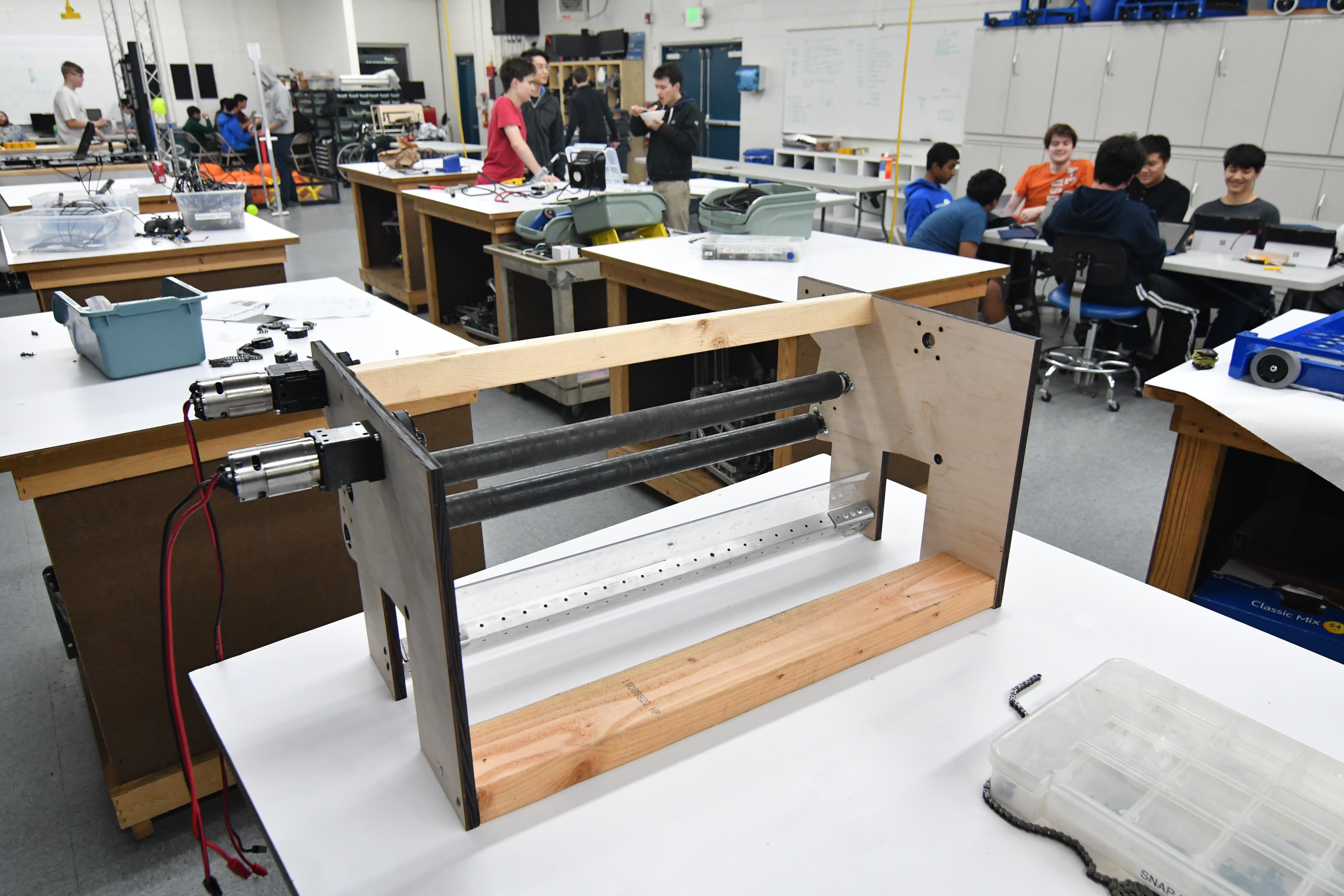
Today, we worked on the CAD of the hopper conveyor assembly. We are using 10 0.875" OD rollers with a center to center distance of 49.5mm. The conveyor is powered by two 775 pro motors with a 3:1 reduction. It will pivot below the intake pivot along a 0.625" OD shaft before/after the match to change batteries and service electronics. The current plan is to have it latch into place with a pin that goes between the side plate of the hopper conveyor and a .25" plate attached to the inside of the shooter uprights.
Programming
Today, we calibrated all 6 PixyCams and outputted all constants to a java file. We tested this on the roboRIO and it worked really well. We changed the lens of some of the cameras to a InfraRed (IR) lens with a narrower field of view with less distortion, which is better suited for the boiler vision detection. We are working on a distance model that based on the image finds the distance to the object is that image, using the pinhole camera model.. Unfortunately, our calculations are very noisy (fluctuate a lot) and are smaller by an order of magnitude. We have yet to refine our code and calculations.
We also tested out the autonomous routine path code, but the NavX board was running the wrong firmware and didn’t work with our code. We will troubleshoot this issue at the next build.
FRC Day 16 Build Blog
Day 16: Zipper Hopper and Intake
Prototyping
Zipper Hopper
Today we solved the problems of the previous designs by removing the polycord and replacing it with chain. While disassembling the prototype, we found another link of the polycord which melted onto the delrin hub, so in the future we’ll definitely avoid using polycord in this type of situation. The chain increased efficiency so much, that we actually ran into problems with our feeder roller. As a result, we found that it needed a second CIM to drive it efficiently without burning out. After testing it, we decided to iterate on the zipper wheels themselves. Changing from an active to passive solution, we changed one side to metal wheels with little traction. Specifically, our intake wheels from 2015, without any polyurethane. On the other side, we added a second mounting hole and added two chain run rollers. We found that this worked well,and we need to continue to iterate and finalize the hopper design.
Intake
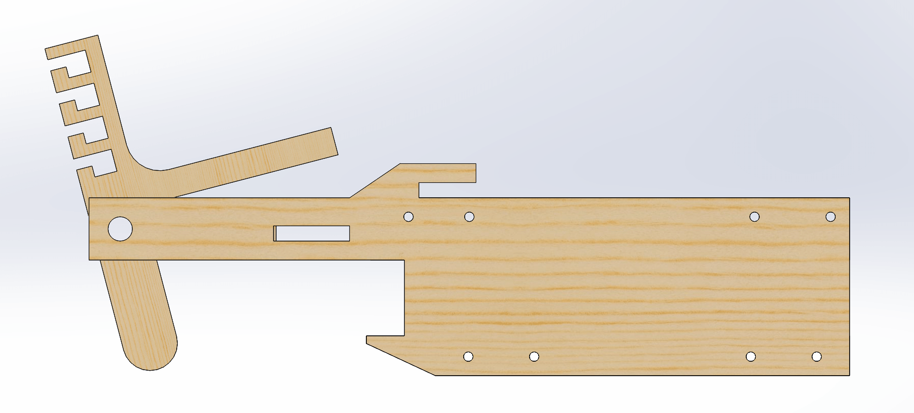
Today for the intake we worked on the side plates and made the geometry match that of the currently-functional prototype. We tried to make them look good and then we pocketed them.
We chose a piston and have a preliminary extra plate that mounts via small brackets to the 3/16" bolts in the drivebase bumper-support tubes. We had to change the motor mount plates so the standoffs would avoid hitting the many paths of belts.
We still need to finalize the packaging of the intake into the overall superstructure and integrate it with the hopper and feeder.
We also need to figure out how to get the polycarbonate ramp to deploy because currently it doesn't fit within the starting configuration when the intake is raised.
.png)
.png)
Programming
Computer Vision
Today we began work on modifying the Android vision tracking app, used in last year’s challenge to aim at the goal, for the boiler target. The underlying thresholding code, which isolates the illuminated (green) retroreflective tape from the rest of the image, will remain the same, but the processing code will need to be changed.
We use OpenCV, the de facto open-source computer vision library. We began with a thresholded picture of the goal that shows only the retroreflective tape on the target. Then, we created a contour, or an outline of the “area of interest.” We initially experimented with this using GRIP, an application that allows one to interact with OpenCV using easy drag-and-drop blocks, but we quickly realized GRIP’s limitations. We then moved to Python for prototyping purposes, and we were able to draw an outline of the contours.
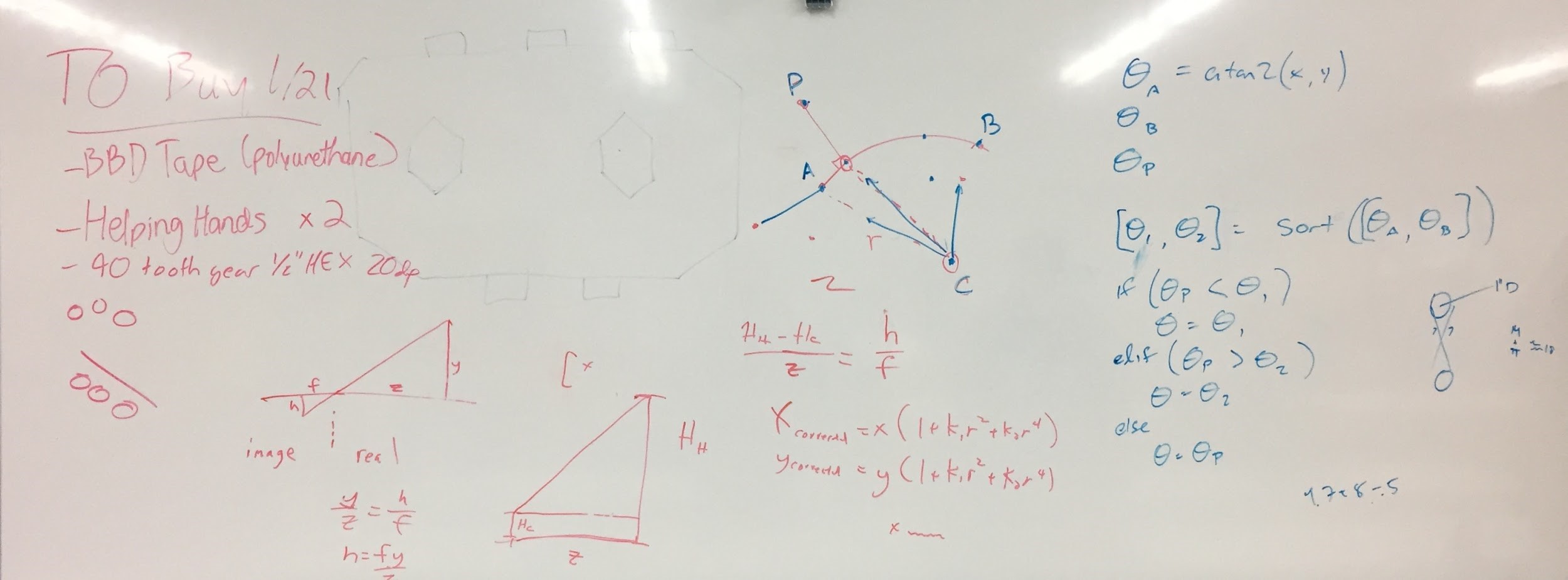
Finally, we also discussed using the pinhole camera model to determine the robot’s distance from from the goal, which determines how fast/hard we launch the ball (Wikipedia Article). Given the actual object height (in inches/cm), the camera’s focal distance (in pixels), and the height of the object in the camera (in pixels), we’re able to calculate the distance from the object. The exact means by which we implement this are to be determined.
If you’d like to help with computer vision, please set up OpenCV for Python (64 bit!) using these instructions.
Thresholded image:

Thresholded, with contours highlighted in green (by the OpenCV program):

Autonomous Code
Today we worked on cleaning up and documenting the autonomous pathing code. As part of the cleanup process, we reworked the pathing code's coordinate system. The old coordinate system was a left handed system, with positive x values to the right and positive y values moving downwards. This placed the origin at the top left hand corner of the field. However, angles still moved counterclockwise, making the whole system convoluted and confusing. The new coordinate system we implemented today is much more straightforward. Positive x is right and positive y is up, while angles increase as they move counterclockwise. This new system makes trigonometric functions far easier to use, as with the old one we would always have to invert any y values.
FRC Day 15 Build Blog
Day 15: Drivebase, Prototypes, and Program
Wiring for Drivebase
Today we began wiring the drivebases. We have all of the Talon SRXs done and we have installed most of the components. We have a lot more work to do, and we will be working hard to get it done as soon as possible.
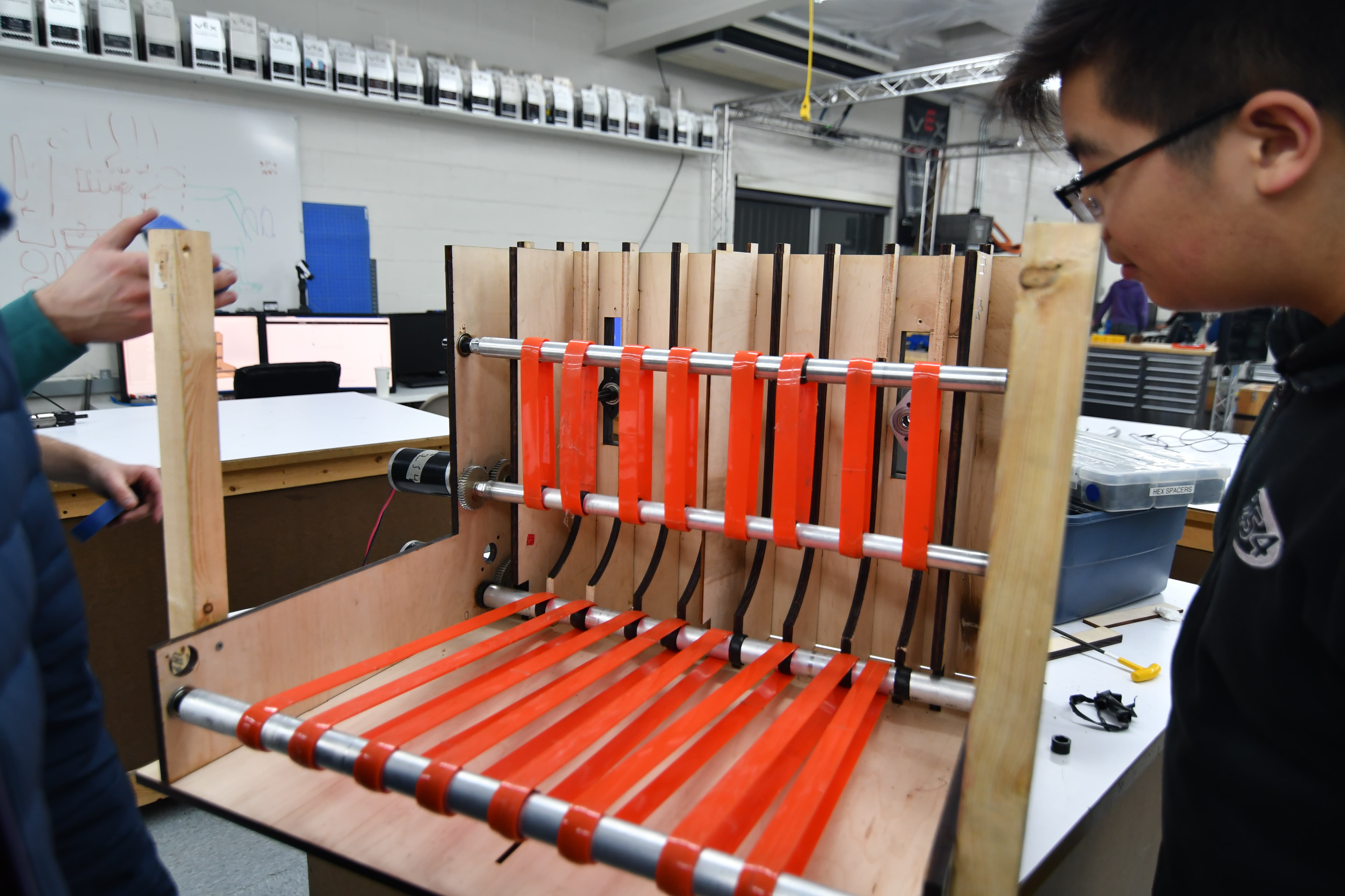
Zipper Hopper
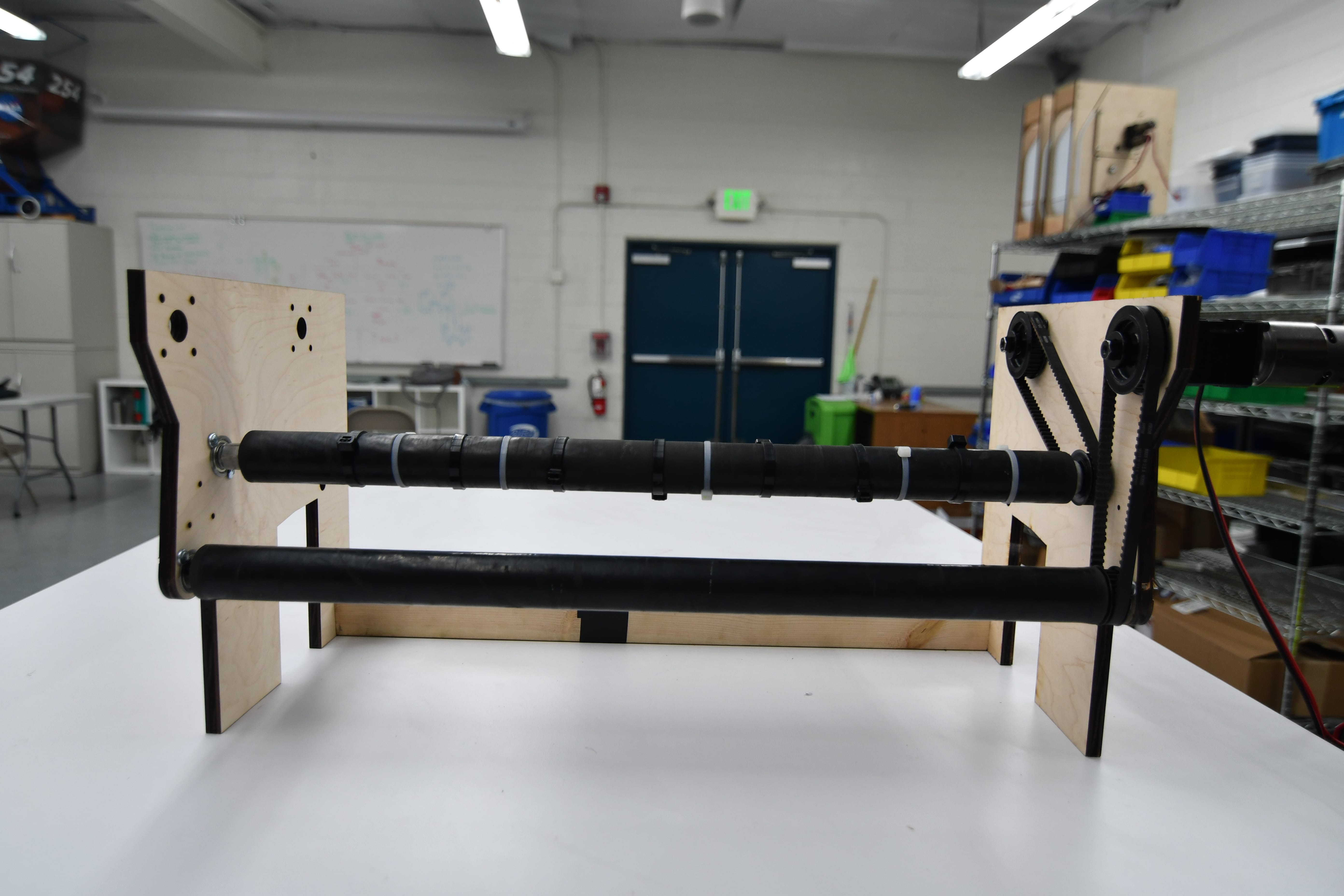
We worked on developing a new zipper hopper. We disassembled the old one, and built a new one with rollers. We built the rollers using aluminum tubes with a 7/8" OD and surgical tubing around them. The hubs are VEX Pro 1/2" hex spacers malleted into the shafts. We beveled the shafts so that the 'plugs' would be as colinear as possible when stuffed into the shafts. We also ran the floor and feeder with polycord rollers. We quickly discovered that after running it for a short period of time, the polycord would break or just slip. We also found that at high RPMs, the amount of friction caused so much heat that the polycord pulleys we were using melted. We then had to transition to belts and pulleys, which fixed some of our problems. After our testing, we found that the rollers would "hot-dog" and sometimes not feed the balls. While it was better than the polycord, it still was not good.
Intake
Today the intake was remade and retested to finalize geometry before it's fabricated out of metal, and we found that the design maintained a good amount of compression on the balls throughout. We did not get a chance to fully test it yet due to some mistakes in the prototype that led to it being remade once more, but it is almost ready to go for thorough testing tomorrow.
Programming
Camera Calibration
Today, we calibrated all six Pixy cameras. We altered our code, so depending on which camera we are using, the code reads the camera matrix specific to that number Pixy. We saved all of these in .txt files in a new folder called resources. The next step is to add this folder to the JAR file (Java ARchive) so that it is deployed onto the robot. Currently, the fps (frames per seconds) in which the calibration program is running at is really low. We sped it up, but that crashed the program, and the calibration wasn’t as good, so we changed it back. We also had some trouble with Pixy #4. There was a black splotch in the top left corner of the image. After unscrewing the lens, we found a speck of dust that we blew away using compressed air from the pneumatic hose. This fixed the camera. Under FRC-2017/camera-calibration/ there is a file titled README.md which contains instructions for calibrating the cameras.
Here is a sample applet which shows how we take an image (shown on the left) and undistort it (shown on the right).
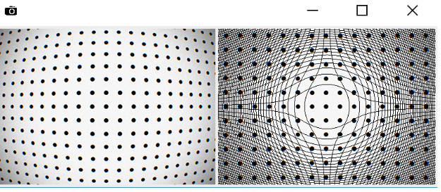
As you can see, the dot grid is significantly straighter in the right image..
Prototyping
We continued to adjust the Talon SRX’s controller to see if we could the PID tuned. Results were not yet conclusive, and there is still more to test and evaluate.
FRC Day 14 Build Blog
Day 14: Intake and Drivebase Progress
Prototyping
Intake
Today, we made a prototype of the intake that had been CADed for use in the real robot, to confirm that everything was up to spec with how we had intended it. We laser cut and assembled it, but did not get through thorough testing yet. The initial testing, however, looks promising.
Zipper Hopper
Today we worked on a zipper hopper/feeder prototype. We began by designing a belted feeder and floor in CAD, and rather than simply being 2 balls wide as the previous prototype, we made it 4 balls wide.This more accurately represents our actual robot. The hopper has a soft wheel between two of the 'lanes' for the balls, causing a zipper effect and a higher throughput. This system seemed to be relatively effective, but the polybelt on the hopper floor and on the feeder posed continual problems, Primarily, the belts were causing too much friction, were moving off of their crowns, and were causing the shaft to bend. We plan to switch to a roller driven design for our next iteration, as we still do not have our desired throughput and they should run more efficiently.
Testing:
Drivebase
Earlier, we had assembled the drivebase parts and sent them in for welding. The drivebase came back from welding today. We finished wire brushing and sanding the welds today, so we are sending it to Gilbert for powdercoating tomorrow morning.
Programming
PIXY Camera Communication
Today, we began integrating undistortion algorithms into the SPI Driver for the PIXY Camera. It is pretty much incorporated into the SPI code, and should work, although it has not been tested yet. The undistortion algorithm has successfully removed the barrel distortion from our PIXY Camera after running OpenCV’s Calibrator to retrieve the distortion coefficients. Now we need to get the distortion constants directly from the output of the calibration file (it is saved as a .txt file) as opposed to defining them in the source code. The code for reading the .txt file is written, but it needs to be set up and integrated.
Prototyping and Testing
After the mechanical team finished the side-by-side backspin shooter on sunday, we were able to test it today. We tested with the SynchronousPIDF that we wrote, and we also tested with the Talon SRX’s on-board PID. From these tests we learned that the Talon’s averaging mechanism is useful, but when it is doing velocity PID, it does not run in voltage compensation mode. Our SynchronousPIDF uses the Talons in Voltage Compensation mode so that the throttle remains constant even if the battery voltage dips due to some other load. This is needed because when the feeder is activated, it drops the battery voltage significantly. We adjusted the constants to try to make up for the sudden dips, but we have not yet found an optimal configuration. Next time, we will try to fix the JRAD Controller that I talked about last time and then we will see how that affects the reliability of the prototype. Even if we perfectly optimize control, this prototype has some inconsistencies mechanically that have affected the trajectories and precision of each shooter.
FRC Day 12 & 13 Build Blog
Day 12 and Day 13: Programming and Prototypes
Prototyping
A lot of things got done with prototyping today. We were able to assess the merits of topspin vs backspin, and we determined that the backspin shooter was better for the following reasons after extensive testing:
-
Balls do not jump out of the boiler like the balls with topspin do
-
The angle did not have to be adjusted as much as the topspin one did when we varied the distance
-
Easier packaging
We shot both the topspin and backspin prototypes at the same trajectory and distance to minimize variables, and we tested at three different distances. We did notice that the topspin shooter had a greater allowable RPM range which makes it easier for software control, but the difference was negligible when faced with all of the cons that come with the topspin shooter.
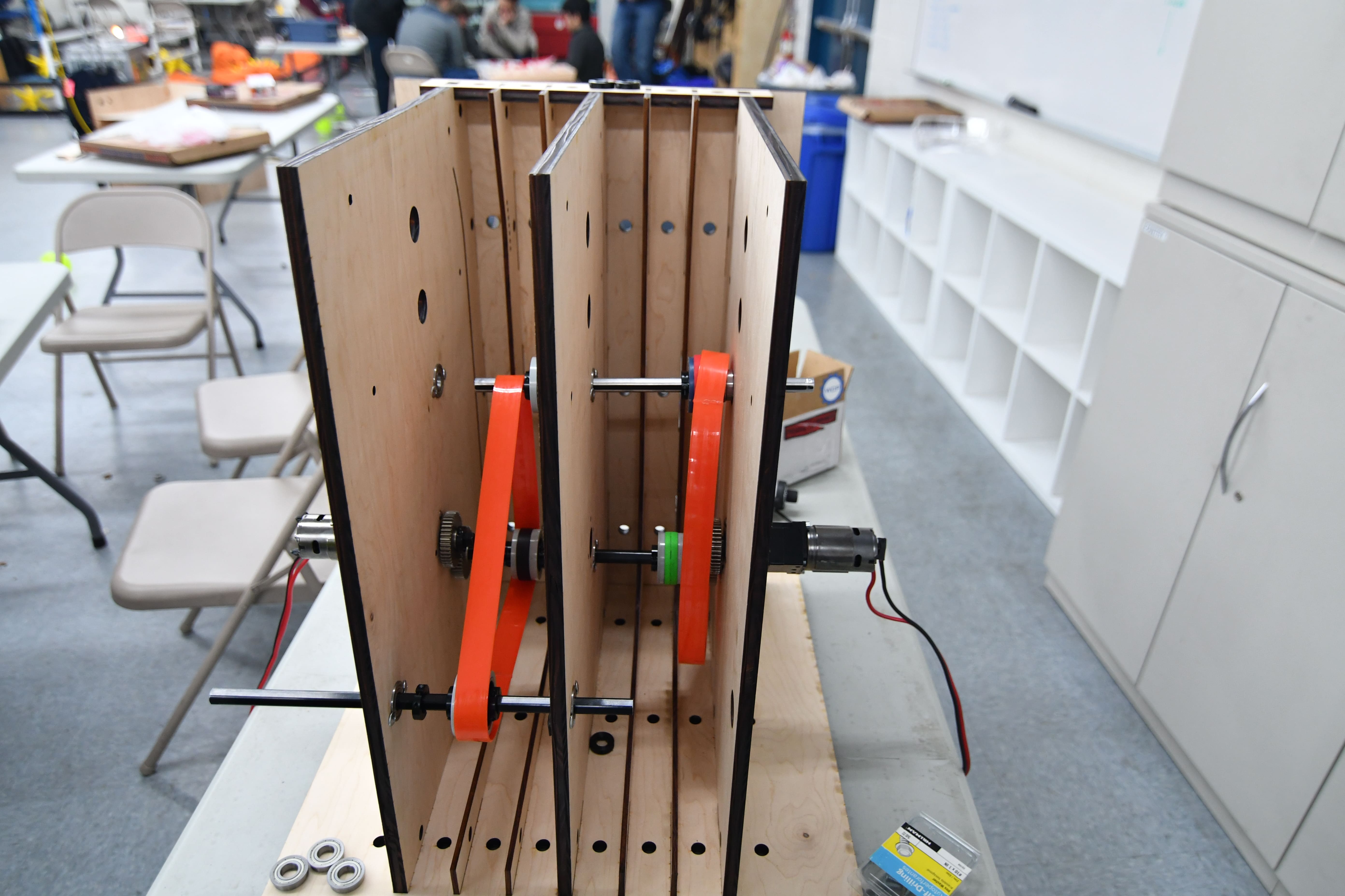
Backspin Flywheel Shooter
After we decided on using a backspin flywheel, we began prototyping a new version that has two channels side by side with a more robust gearbox. This setup shoot allow us to experiment with different variables to determine the best control loop to fire two rapid streams side by side and avoid mid-air collisions. We wanted to remove the inefficiency of the VersaPlanetary gearboxes from our prototypes, so we designed a belted gearbox. We wanted to replicate the 3:1 gearbox which we used for our prototypes, but due to part limitations, could only build an 8: 3 design. We decided that this was close enough to our previous designs and CNCed the parts. We assembled the gearboxes, implemented a polybelt feeder, and added an encoder onto the shooter shaft. After running the gearboxes, we found them to be slightly constrained, but they work and should better replicate our actual shooter. They currently have 4 775 Pros, but we can easily add or remove more motors (max 6). As soon as we get the programming sorted out, we should be able to tune and test this flywheel.
Hopper Conveyor Belt
Today, we also worked on the hopper conveyor assembly. It is currently angled at 5 degrees and has a 3:1 reduction. Using polybelt, it feeds balls into the feeder leading up to the shooter. A funneling feature still has to be incorporated and the assembly itself may be changed depending on results from the hopper prototyping efforts.
Feeder
Today, we worked on the feeder. Because we were unable to get the previous iteration of the feeder to run smoothly with the output holes, we decided to reduce that number to two and make a few other small modifications to the general design. This new version was then designed and constructed, but we found that the improvement was not as significant as we originally imagined it would be. In fact, we still had problems with the motors burning out and we really struggled to get a lot of balls to run through the system. In order to solve this problem, we tried a couple of things. First, we tried adding zip ties to some parts of the roller, but this simply caused jamming. Second, we tried increasing the spacing between the two output holes as making them significantly more defined. This, unfortunately, did not help that much. Finally, we tried using a drill with some wheels on the end to agitate the balls, somewhat like a KitchenAid mixer. This helped a bit more, but we still reached the conclusion that it was simply a bandaid to a bigger problem.
Manufacturing
For these two builds, we manufactured all the parts for the drivebase and began assembly. Because of design changes, we manufactured all the parts for the bumper mounts on the manual mill. We also prepped the belly pan by countersinking the holes for the rivets and deburring it after getting it from the water jet.
Programming
Shooting Control
Today, we began to brainstorm better ways to control the flywheel, and we arrived at the following scheme (which we call the JRAD Controller):
v[t + dt] = kf + kj * dt * (kLoadRatio * setpointSpeed – curSpeed)
Where dt is measured cycle time, kj and kLoadRatio are tuned/calculated, and kf is set to some constant like 8 (Volts)
This equation represents the initial version of the JRAD controller (named after Jared, who made the equation). This version is actually incorrect, and next build we will be adding an additional term to make it an integrating controller as opposed to a proportional + constant term controller. This new equation will be:
v[t + dt] = kf * setpointSpeed + v[t] + kj * dt * (kLoadRatio * setpointSpeed – curSpeed)
Where v[t] is the previous cycle’s output in volts, and where kf is multiplied by the setpoint so that it works at more than one speed
What this controller does it that it anticipates the drop in RPM during a stream of balls, and increases the RPM set point accordingly. This adjustment is the kLoadRatio, which is the key feature of this controller.
To tune the controller, you would start with kLoadRatio at 1, kj at some nonzero small number, and kf also at zero (kf allows the controller to reach the steady state faster, but is never necessary). Here is the initial scenario:
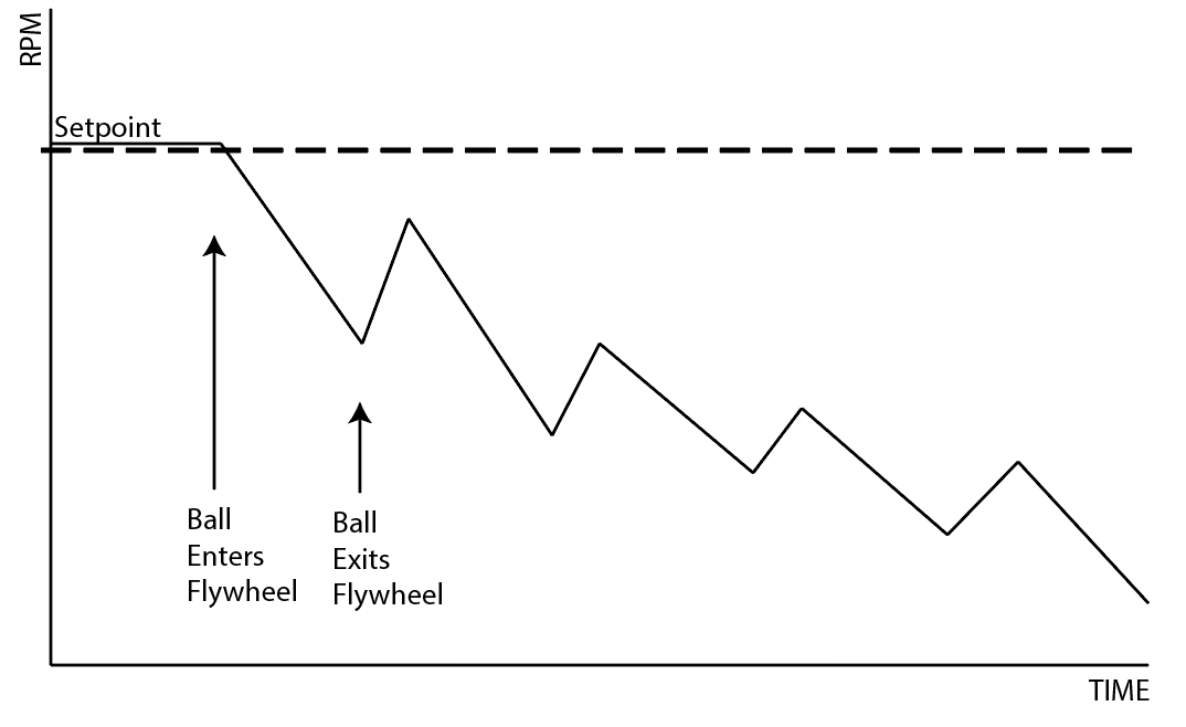
The difference between the dips when balls hit indicate that the controller is not tuned correctly. Each valley should be at the same height, even if it is below the steady state. KJ should be increased in the above scenario. If the valleys increase over time, then KJ should be decreased. Eventually the RPM vs Time chart should look like this:
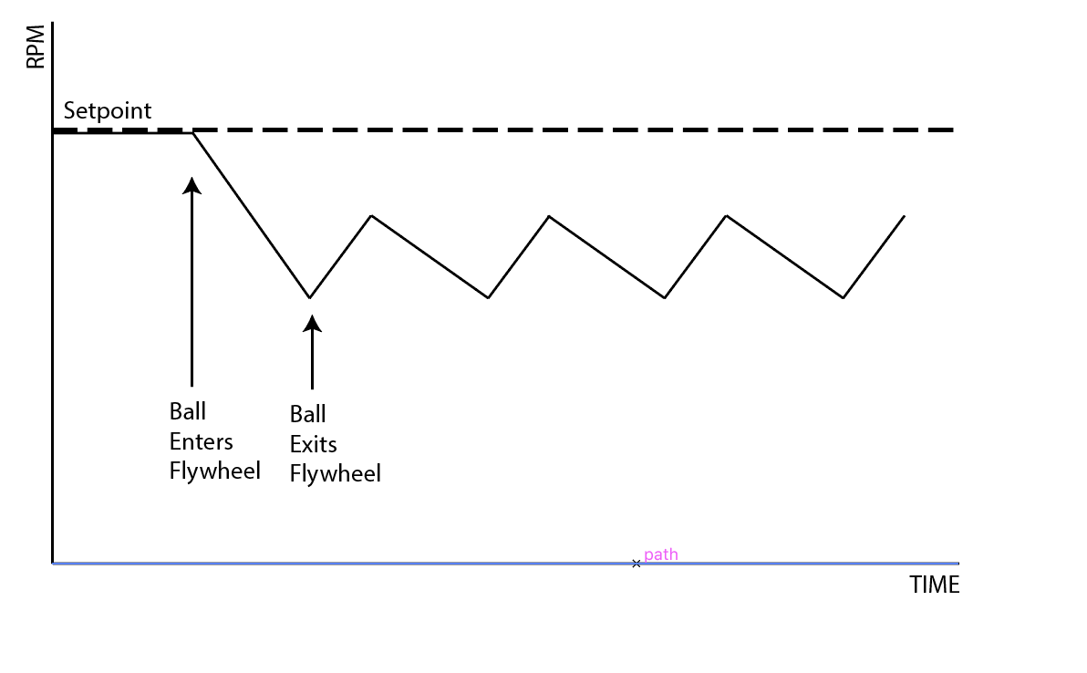
This is definitely better because the balls are consistently exiting at the same speed, however we aren’t getting to where we want to be when we shoot. When this is achieved, we can finally calculate KLoadRatio. To do this, we take the setpoint and divide it by the Lowest RPM, which should now be constant for every ball. This yields a number greater than 1. Now the output of the function looks more like:
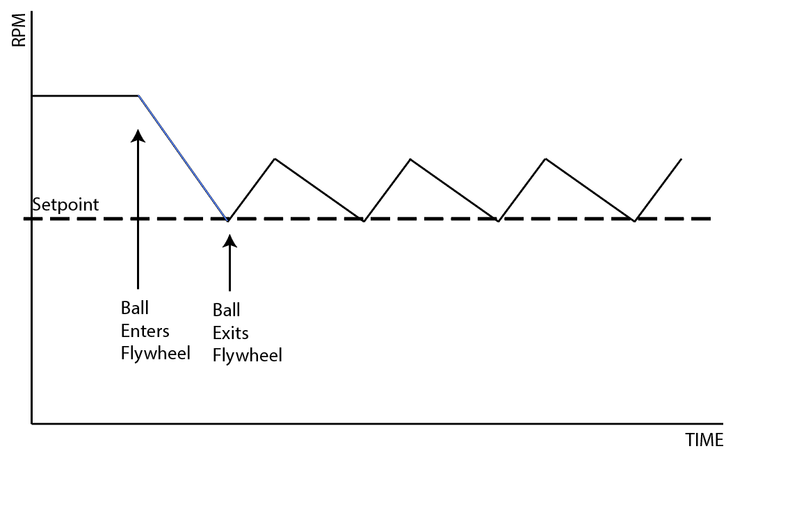
Notice that the steady state is now greater than the set point. This is because it anticipates that the RPM will decrease when a ball contacts the flywheel and it increases the speed before the ball hits so that the speed is correct when it actually is released from the shooter.
Here are videos of the testing we did.
Robot Vision
Today, we found the correct equation for using the camera matrix and distortion coefficients and undistorting an image. We found the equation in this Wikipedia article. This is working pretty well. Now we just need to implement it into the robot code, and it should be done.
We also discussed whether or not the PIXY Camera would be useful for the targets this year. Right now, the current plan is to use the pixy for the gear vision target, but not the boiler. We believe that the low resolution of the Pixy camera would lead to a high error in locating the boiler, and since the margin for error is so small for our shooter prototypes (see Prototyping section of this blog), we need to have a more accurate system. Thus, we resurrected the old vision system using smartphones from last year, and initial tests are promising. We need to tune the OpenCV, but we were able to get it to reliably filter the boiler target:

Also, we refactored the SPI communication driver for the PIXY Camera so that it is better integrated into the codebase and so that it can support multiple cameras.
Autonomous Path Following
Today, we continued work on the autonomous pathing system. We finally got the code to the point where we were able to deploy it to a spare drivetrain and test. We began by tuning the PIDF constants for the drivetrain and setting constants for the wheel radius, drivetrain width, and several pathing parameters. We had to make many several bug fixes and changes to our code, including rewriting the circle function in out AdaptivePurePursuitController class. We also faced several hardware problems, like the encoders falling off and one of the gearboxes breaking.. However, by the end of build, we were able to get the robot to drive along curved and straight segments of the path with a decent margin of error. There is still much work to be done on the pathing system, including improving its accuracy and implementing turns in place.
FRC Day 11 Build Blog
Day 11: Prototypes and Drivebase
Prototyping
Shooter
Today we worked on duplicating the single wheel backspin flywheel with 4″ fairlane wheels. We wanted to test the accuracy and plausibility of two side-by-side flywheel shooters, so we built another shooter. We also altered the first backspin flywheel shooter by replacing the side plates, which allowed us to put both shooter motors on the same side. This alteration was made to make the two side-by-side shooters compatible
Hopper Feeder
Today, we began detailing the hopper feeding mechanism. The current plan is to have it powered by two 775 pros with a reduction and to power both the front and back rollers via friction with the polybelt. The feeder is slightly angled and will include a funnel consisting of two tubes angled towards the middle of the back roller. The feeder will also rotate on the same axis as the intake. Rotation will be necessary to access the electronics on the baseplate between matches (i.e. Switching batteries)
Shooter Feeding Trough
Today, we built a second trough and added 775 Pro motors with a 3:1 reduction on both. While running, a polybelt moves the balls at an estimated 18 balls per second.
Intake
Today we finished assembly of the new intake prototype without a ramp and tested it out. We found that there was too much compression between the intake rollers and the floor/bumper, so we adjusted the mounting of the intake accordingly. What we found was that the center drop of the robot was enough to upset the outer roller’s compression such that when the robot leaned back, it would not pick up balls. Of course, this was a big problem, so we made the intake pivot around a point inside the robot, very similar to how the real one would. By having the intake itself able to pivot, we think that it’ll be able to move up and down accordingly as we drive into dense clusters of balls, fixing the issue of the intake bogging down. We finished assembling the intake, but have yet to test it. Our first job on Friday will be to get more tests running, and we’ll go from there.
Manufacturing
Drivebase
A group of students started manufacturing the parts for the drive base so we can send it out for welding next week. We were milling the parts for the bumper mount on the mill and ran some other parts on the CNC.
FRC Day 10 Build Blog
Day 10: Shooter Improvements & More
Prototyping
Backspin Single Wheel Flywheel
Today, we finished the 4" Fairlane Single Wheel Backspin Prototype that we started on Saturday. We tested for the entirety of the build and received great results. While single shot accuracy was consistent, when we started pushing in balls at a higher speed, we found that the shooter was somewhat inconsistent. In exploring other options for more consistent feeding, (and by consequence shooting) we decided to change the VersaPlanetary gearbox running the polybelt feeder from a 5:1 gear ratio to a 1:1 ratio. We found this speed to be much more efficient. At the end of the night, without pushing the balls (so solely gravity fed), we managed to shoot around 25~ balls. After missing the first shot or two, we managed to make every subsequent shot. While this only shot at around 2-3 balls per second, it is a first step towards proving our design. We found the precision to be incredible, but more importantly the rate of fire was impressive! This was most likely due to the extra mass of the wheel resulting in inertia to counteract fluctuations in rotational speed as balls compress against the wheel. We began making a second iteration of this prototype in an effort to put it next to the previous working one. We would then shoot them in the same direction and verify that two shooters side by side is a feasible option for accuracy and rate of fire. We finished laser cutting the new parts, acquiring the materials, and sorting out all the tools. We only need 2 more 3:1 VEX Planetary Gearboxes, and then we can assemble the prototype and test.
Testing:
Intake
Today we worked on a new and improved design for the intake. We CADed new sidewalls with updated geometry, in order to get rid of the ramp and make the intake easier to deploy. We laser cut the sidewalls and are almost done assembling the new prototype. The plan for the future is to finish it early on Wednesday, then run tests to see how effective it is.
Intake Feeder
Today at the lab, we worked on the feeder for the intake. Unfortunately, the whole process took a long time because we struggled so get the vertical portion of the feeder to spin at all due to efficiency issues with the design. Once we did get it working, however, we modified the lower roller in order to increase the spacing between it and the vertical roller. Though this would be effective, but generally we found that the current design simply needs too many modifications, so it would just be easier to do a complete redesign. The next step is to look into other feeder systems that are potentially more efficient and faster.
Rope Climber
Today, the team working on the rope climbing switched the previous 775 pro motor for a CIM motor and succeeded in climbing the rope. We first laser cut a new piece of wood that would connect to a cross bar on the robot holding the motor and comb shaft. We moved the holder for the motor and shaft one inch up to provide clearance for the motor as well as give the comb more room away from the crossbar. After this, we assembled a CIM motor planetary gearbox in which we geared the motor 1:9 and this ratio was also later increased through the gears on the shaft to 1:45. This proved to be enough to lift the approximately 30 pound previous drive base of our 2015 robot, Deadlift. Without success, we found that undoing the rope on the comb proved to be very difficult and time-intensive, so went back to the drawing boards and found that a velcro design could work out well while taking less time to undo. We will assemble and test this during the next build.
Testing:
Programming
Testing Shooter Prototype
Today we made leaps and bounds with the shooter prototype. We were able to score 30 balls consecutively feeding into our dual-motor flywheel shooter prototype. To do so, we fine-tuned the PIDF constants in the robot code to ensure that motor speed would remain constant even with the load from the balls, which ensures more consistent, accurate shots. This is a breakthrough for our shooter prototypes, the first time where we’ve been able to make a majority of shots from a stream. We still have to improve the firing rate of our prototype; we were firing at ~3 balls per second.
FRC Day 9 Build Blog
Day 9: Flywheel and Prototypes
Prototyping
Topspin Single Wheel Flywheel
The topspin shooter continued testing today with several small changes made throughout the build. We remade yesterday's prototype and varied the hood length to see how it affected accuracy. We started the day by testing the 4" flywheel with top spin. We took the working design, and redesigned the prototype to not be adaptable, and in doing so we also designed an integrated feeder. This design worked relatively well. We iterated on the optimal amount of wrap on the ball, starting with around 120 degrees, and going as far as 80 degrees, without testing further. As we iterated and continued testing, we realized the difficulty of packaging a topspin flywheel, so unless we are able to show that topspin is more consistent, it is unlikely that we will use it in the final design. We also tested a backspin 4" flywheel by simply rotating the shooter. The design worked, but needed further optimization. We set upon further iterating on this by CADing an entirely new design.
Backspin Single Wheel Flywheel
Today, we remade the single 2" Fairlane Flywheel prototype, but this time we fixed all the little bugs from before as well as added two more 2" wheels in the exit. This concept was to see if it would make the shot more accurate, but it didn't pan out. We reverted to the single wheel design, which worked beautifully. This backspin shooter was really consistent and accurate for the first successful iteration and it also makes packaging the shooter into our robot much easier. We also worked on designing a three-parallel-shooter prototype that would have three of these shooters side by side for maximum shooting rate..
Drivebase CAD & Design
We continued work on drive frame detailed design. Other team members started exploring space claim models for the entire robot, including the hopper, shooter, gear mechanism and drive train. We also looked at possible packaging for the topspin shooter that was working well. We decided that for simplicity, the ball feeder chute on the rear of the robot should not deploy over the bumper, and that it is better for it to stay rigid for consistent ball feeding. We still plan to deploy the hopper on the front, and possibly sides, of the robot.
-min.jpg)
-min.png)
Field Construction
We cut plastics and installed the top of boiler so that more accurate shooter testing could proceed.
Manufacturing
We will be continuing our work on making drive gearboxes. We finished de-tabbing gearbox plates and started making gearbox standoffs. Several students continued on mill/lathe training with test parts.
Programming
We restructured the robot code to offload control of the drivetrain from the Drive subsystem file to the main Robot Java file. The Drive system’s code runs every 1 ms, while the robot’s code runs every 5 ms. The driver station sends and drive data every 5 ms, so moving the code saves considerable processing power. This also allows for other functions to be implemented in the Drive subsystem.
Following our all-hands meeting yesterday, we finished the autonomous routine visualizer, which allows us to design and visualize an autonomous routine using a series of points. We also finished a parser that turns the visualizer output into usable robot code. We also implemented an adaptive pure pursuit controller, which helps the robot correct any deviations and return to its pre-planned route. This requires an odometer to track the robot’s distance travelled and heading, which we also implemented. We are currently establishing the groundwork for the robot’s autonomous routine, which we will implement when we have a final robot.
Camera calibration
Today we finished camera calibration code. It works really well, and now outputs the distortion numbers to a .txt file for easy access. Now, we are working on incorporating that into the SPI code so the Roborio has access to the undistorted image data. We need to figure out how to undistort the image while keeping it in a RAW format.
In addition to receiving calibration results, we discussed how to then take these calibration constants and apply them to remap the raw image coordinates to adjusted ones that map to physical locations on the field. We consulted a handy opencv guide.
Here's the picture of our whiteboard discussion:
Programming On The Prototypes
A lot of progress was made today with prototyping. We wrote new code to add a closed PID control loop to the feeder of the new overhand/backspin prototype and we returned constants to work with the new flywheel. In doing this, we discovered numerous bugs in the constant setting code and we have remedied many of them. Most of the time was spent supporting the prototyping effort with various control tweaks to maximize performance.
FRC Day 8 Build Blog
Day 8: Flywheel
Prototyping
Topspin Single Wheel Flywheel
Today, we iterated on our flywheel prototype. We decreased compression by around a half inch, and found drastically improved results. Our first test had over 90% accuracy. We attached a second motor to be able to test high throughput shooting well. We made our feeder perpendicular to the shooter, and found some shot inconsistency from balls later in the feeder. We realized that a gravity fed shooter might not work well, and added a powered feeder shaft. Our shot-shot consistency improved greatly for high throughput testing, but still isn't excellent.
Testing:
Backspin Single Wheel Flywheel
Today, we worked on a single 2" Fairlane wheel flywheel with 1/4" compression fed by a polybelt feeder, powered by a 1:1 VEX Planetary Gearbox and Motor. The wheel – powered by 2 Planetary Motors – had lots of power, but was very inconsistent. Moving forward, we will want to constrain the shot on the sides as to avoid inaccuracies from side to side (this will most likely be with 1/8" polycarb sheets double-stick taped on). To help the ball shoot more accurately as it exits, we will either shorten the hood so that the ball is in contact with the wheel right before it exits. We may also try to add rollers to improve the shot accuracy. We also had trouble with the polybelt feeder, as the polybelt (which had too much compression on the ball) would skip along the ball as it pulled it up, getting worn down and rendered virtually ineffective in the process. To fix this, we plan to move the feeder out slightly to get the right amount of compression and also have a curved backing so that there are no dead zones in the feeder system. We also plan to make another prototype with a similar design, but less inaccuracies in alignment of the wheel and feeder.
Fuel Intake
Today we made good progress on the intake. We added two motors (775 Pros) and changed the gear ratio to an overall 3:1. The results were significantly better than the previous test with 1 motor; now, driving at full speed into a dense pack of balls, we were able to pick up almost all the balls and hold them in our hopper. However, this current design uses a small incline right in front of the bumper to help pull the balls up and over, which we would like to get rid of for the final design, because it makes deploying the intake much more complicated. We created a new prototype that does away with the ramp by changing the bottom roller geometry relative to the bumper, and from initial testing, the results looked very promising. More prototyping is needed to see if the new design with no ramp is effective as the previous prototype; however, as the intake nears completion we may prioritize finalizing the shooters.
Testing:
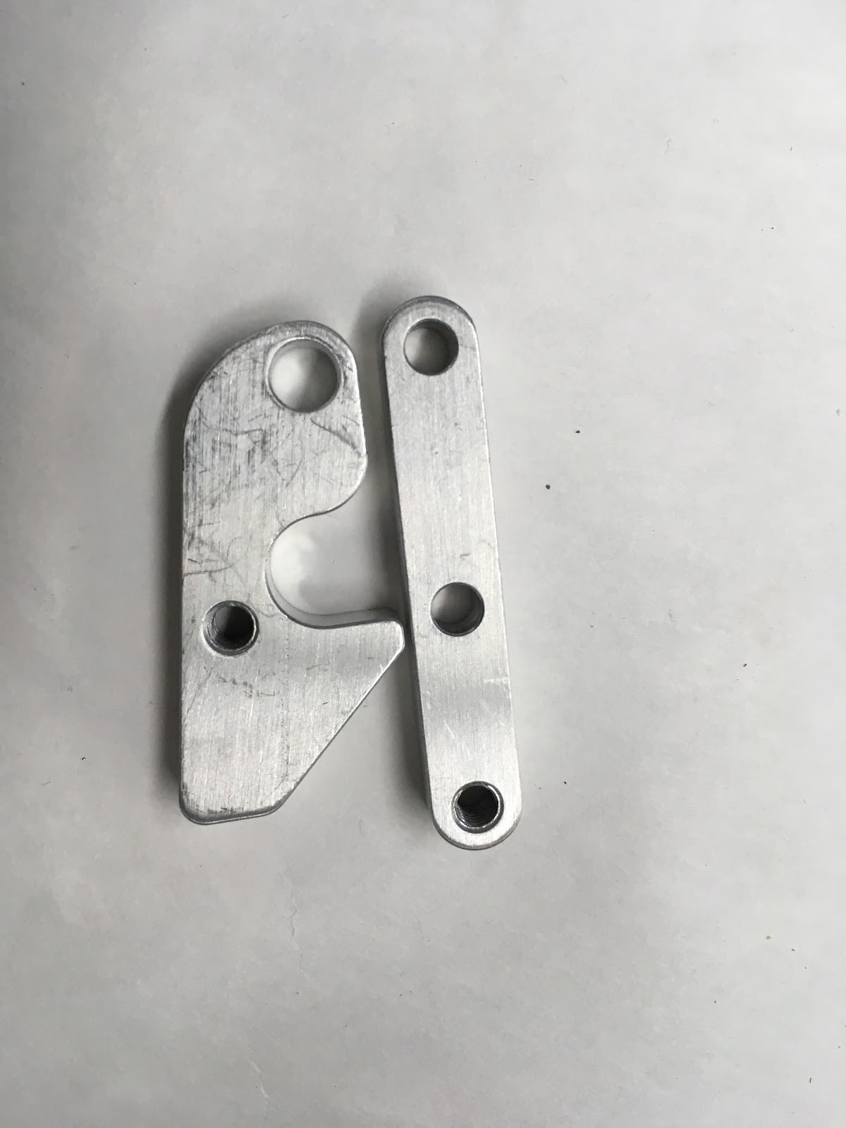
Gear Intake
Today we tried out a completely new design for the gear intake. Instead of placing the pivot point for the hook very close to main body of the grabber, today’s version switched that pivot point to the very front part of the hook. Feel free to compare the picture below to the pictures from the last couple blogs to see the change in design.
Although we did not finish fully assembling the new design, we believe that this new version will give us a significantly better grip on the gear.. Unfortunately, our initial impression after assembling part of it at build tells us that this new design might actually take up even more space than the previous version, which might outweigh the extra grip. The next step in the development process with involve finishing the construction of this design and evaluate possible areas of improvement. Once we have multiple gear grabber designs working at their full potential, we will compare the different versions and begin designing a metal version for the robot.
Drivebase
We made adjustments to the drivebase CAD by moving down the crossbar to be flush with the baseplate while cutting out slots for chain runs. We also changed the corners on the rear to have a 45 degree slant for better gear intake and made it with two pieces of 1×1 tubing. Moving forward, the last electronics (pcm, vrm) and pneumatics (solenoid/manifold, compressor) have to be finalized in addition to final dimensions.
Programming
Today, the programming subteam discussed robot motion control with Jared. Moving a robot from point A to B requires waypoints, curvature, and physical constraints of the robot. For instance, a robot cannot instantly accelerate from standstill to full speed, and it cannot instantly decelerate to a standstill without damaging its gearbox components or slipping the wheels. Motion profiling allows the robot to move in a controlled fashion, minimizing acceleration and deceleration.
We also discussed factoring in obstacles like slippage and wrinkles in the carpet. In techno-speak, we would maintain an “odometer” to track our robot’s total movement, then we would calculate the robot’s deviance from the actual path. We would then calculate the closest point on the path, calculate the distance from the robot to the point, then draw a circle using the point as the center and the distance as radius. This path would be used to bring the robot back on track.
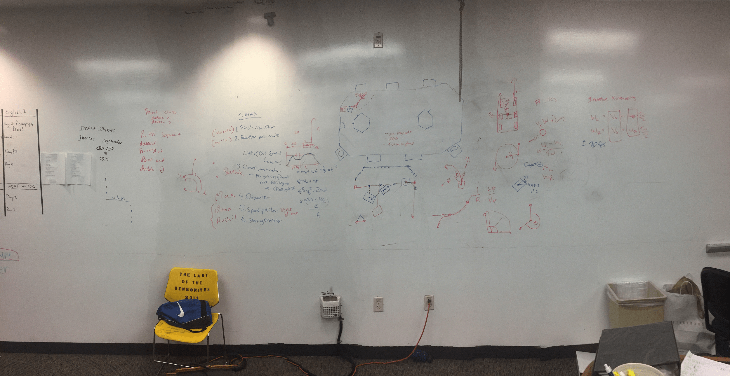
We divided the programming subteam up into six projects: finishing the autonomous mode visualizer, creating a RoboRIO path reader that would parse the visualizer output, calculating the closest point, creating an odometer, a speed profiler, and a steering controller. Meeting minutes are in the picture below:
For the PixyCam, we made significant improvements with the SPI interface. The interface works, but with a few bad bytes. We should be able to fix these kinks soon. Also, we’ve made leaps and bounds forward with camera calibration, and distortion is much less of a problem.
